U.S. Pat. No. 8,164,567
MOTION-SENSITIVE GAME CONTROLLER WITH OPTIONAL DISPLAY SCREEN
AssigneeMQ Gaming LLC
Issue DateDecember 8, 2011
Illustrative Figure
Abstract
A wireless input device for playing an interactive motion-sensitive game using a wireless-compatible game console in which a virtual play environment is represented through one or more computer-animated visual, aural or tactile effects is provided wherein game play is conducted by moving, shaking, twisting, waving or pointing the input device in a particular manner. The input device can include motion-sensitive circuitry and/or command circuitry for generating control signals and/or an effects generator and associated control circuitry to enable the input device to selectively generate at least one visual, aural or tactile effect comprising sound, lighting or vibration. The input device can include a wireless transceiver for providing two-way wireless communication with the wireless-compatible game console. An optional display screen displays short text messages received through wireless communications with the wireless-compatible game console.
Description
DETAILED DESCRIPTION For convenience of description and for better clarity and understanding of the invention similar elements to those previously described may be identified with similar or identical reference numerals. However, not all such elements in all embodiments are necessarily identical as there may be differences that become clear when read and understood in the context of each particular disclosed preferred embodiment. Interactive Wand A wand is provided that allows play participants to electronically and “magically” interact with their surrounding play environment simply by pointing or using their wands in a particular manner to achieve desired goals or produce desired effects within the play environment. Use of the wand may be as simple as touching it to a particular surface or “magical” item within a suitably configured play environment or it may be as complex as shaking or twisting the wand a predetermined number of times in a particular manner and/or pointing it accurately at a certain target desired to be “magically” transformed or otherwise affected. For example, various wand-compatible receivers may be distributed throughout a play facility that will allow wand users to activate various associated play effects and/or to play a game using the wand. As play participants play and interact within each play environment they learn more about the “magical” powers possessed by the wand and become more adept at using the wand within various game contexts to achieve desired goals or desired play effects. Optionally, play participants may collect points or earn additional magic levels or ranks for each play effect or task they successfully achieve. In this manner, play participants may compete with one another to see who can score more points and/or achieve the highest magic level. FIG. 1illustrates the basic construction of one preferred embodiment of an interactive “magic” wand toy100having features and ...
DETAILED DESCRIPTION
For convenience of description and for better clarity and understanding of the invention similar elements to those previously described may be identified with similar or identical reference numerals. However, not all such elements in all embodiments are necessarily identical as there may be differences that become clear when read and understood in the context of each particular disclosed preferred embodiment.
Interactive Wand
A wand is provided that allows play participants to electronically and “magically” interact with their surrounding play environment simply by pointing or using their wands in a particular manner to achieve desired goals or produce desired effects within the play environment. Use of the wand may be as simple as touching it to a particular surface or “magical” item within a suitably configured play environment or it may be as complex as shaking or twisting the wand a predetermined number of times in a particular manner and/or pointing it accurately at a certain target desired to be “magically” transformed or otherwise affected.
For example, various wand-compatible receivers may be distributed throughout a play facility that will allow wand users to activate various associated play effects and/or to play a game using the wand. As play participants play and interact within each play environment they learn more about the “magical” powers possessed by the wand and become more adept at using the wand within various game contexts to achieve desired goals or desired play effects. Optionally, play participants may collect points or earn additional magic levels or ranks for each play effect or task they successfully achieve. In this manner, play participants may compete with one another to see who can score more points and/or achieve the highest magic level.
FIG. 1illustrates the basic construction of one preferred embodiment of an interactive “magic” wand toy100having features and advantages in accordance with the present invention. While a magic wand is specifically contemplated and described herein as the most preferred embodiment of the invention, those skilled in the art will readily appreciate from the disclosure herein that the invention is not limited to wands, but may be carried out using any number or variety of other objects and toys for which it may be desirable to imbue special “magic” powers or other functionalities described herein. Other suitable magical objects and toys may include, for example and without limitation, ordinary sticks, tree branches, flowers, swords, staffs, scepters, whips, paddles, nunchuks, cricket bats, baseball bats, various sporting balls, brooms, feather dusters, paint brushes, wooden spoons, chop sticks, pens, pencils, crayons, umbrellas, walking canes, candy canes, candle sticks, candles, tapers, musical instruments (e.g., flutes, recorders, drum sticks), books, diaries, flashlights, telescopes, kaleidoscopes, laser pointers, ropes, tassels, gloves, coats, hats, shoes and other clothing items, fishing rods and simulated fishing rods, dolls, action figures, stuffed animals, rings, bracelets necklaces and other jewelry items, key chain trinkets, lighters, rocks, crystals, crystal balls, prisms, and various simulated play objects such as apples, arranges, bananas, carrots, celery and other fruits/vegetables. However, magic wands are particularly preferred because they are highly versatile, can transcend a wide variety of different play themes and play environments, and wands can be customized and personalized in their fabrication, assembly and finish as will be described herein in more detail.
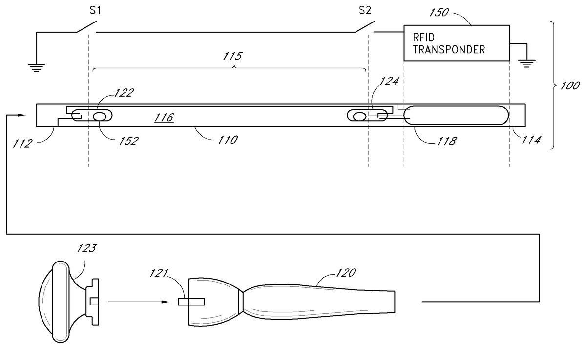
As illustrated inFIG. 1, the wand100essentially comprises an elongated hollow pipe or tube110having a proximal end112and a distal end114. An internal cavity116is preferably provided to receive and safely house various circuitry for activating and operating the wand and various wand-controlled effects (described later). Batteries, optional lighting, laser or sound effects and/or the like may also be provided and housed within cavity116, if desired, as will be described in more detail later. An optional button may also be provided, if desired, to enable particular desired functions, such as sound or lighting effects or longer-range transmissions. While a hollow metal or plastic tube110is preferred, it will be appreciated that virtually any other mechanical structure or housing may be used to support and contain the various components and parts described herein, including integrally molded or encapsulated containment structures such as epoxy resins and the like. If a metal tube is selected, care must be taken to ensure that it does not unduly interfere with any of the magnetic, RFID or RF/IR devices described herein. Thus, for example, any RF antennas should preferably be mounted near or adjacent an end opening and/or other opening of the tube110to ensure adequate operating range and desired directionality.
The proximal end112of tube110is preferably adapted to secure the tube110to an optional handle120. The handle120may further include securement means, such as threaded stud121, snap latches, mating magnets or the like, for receiving and securing an optional decorative knob123. For example, knobs123may be purchased, selected and/or earned by play participants as they advance in a game and/or when they play different games. The distal end114of the wand is preferably fitted with an RFID (radio frequency identification) transponder or tag118that is operable to provide relatively short-range RF communications (less than about 200 cm) using one or more RFID reader units or reader/writer units (sometimes referred to herein as “receivers” or “transceivers,” respectively), described in more detail later. The transponder118contains certain electronics comprising a radio frequency tag pre-programmed with a unique person identifier number (“UPIN”). The UPIN may be used to identify and track individual wands and/or play participants. Optionally, each tag may also include a unique group identifier number (“UGIN”) which may be used to match a defined group of individuals having a predetermined or desired relationship.
The RFID transponder is preferably used to store certain information identifying each play participant and/or describing certain powers or abilities possessed by an imaginary role-play character. For example, players may advance in a magic adventure game by finding clues, casting spells and solving various puzzles presented. Players may also gain (or lose) certain attributes, such as magic skills, magic strength, fighting ability, various spell-casting abilities, combinations of the same or the like, based on game play, skill-level and/or the purchase of collateral play objects. Some or all of this information is preferably stored on the RFID transponder118so that the character attributes may be easily and conveniently transported to various compatible play facilities, games, video games, home game consoles, hand-held game units, and the like. Alternatively, only the UPIN and/or UGIN are stored on the transponder118and all other desired information is stored on a computer-accessible database indexed by UPIN and/or UGIN.
Operation of the transponder118(and/or other wireless communication devices described later) is preferably controlled by internal activation circuitry115comprising, in the particular embodiment illustrated, a pair of series-connected mercury tilt sensors122and124(represented in the corresponding schematic diagram as switches S1and S2, respectively). As illustrated inFIGS. 2A and 2Beach mercury tilt sensor122,124comprises a sealed, evacuated glass bulb130within which is contained a small ball of liquid mercury. A pair of electrical leads134extends through the glass bulb130at the sealed end thereof and form closely spaced contacts136. In one orientation (e.g.,FIG. 2B) the ball of mercury132is drawn by gravity to cover or envelope the contacts136, thus completing the electrical circuit and closing the switch S1/S2(ON state). In all other orientations (e.g.,FIG. 2A) the ball of mercury132does not contact or envelope both contacts136and, thus, the circuit remains open (OFF state). The particular orientation and tilt angle required to trigger either ON or OFF conditions will depend on the size of the glass bulb130, amount of contained mercury132and the size and spacing of contacts136. If mercury sensors are used, preferably they are encased in a metal and/or epoxy jacket so as to ensure against breakage and possible health and environmental hazards. Preferably, each mercury sensor is encased in epoxy within a sealed stainless steel ferule.
Alternatively, one or more micro-ball tilt sensors136or138may be used instead of or in addition to mercury switches122,124. For example,FIGS. 3A and 3Bare schematic illustrations of a micro-ball tilt switch136(normally closed configuration) that may be adapted for use in accordance with an alternative embodiment of the invention. The tilt switches136,138generally comprise upper and lower conductive enclosures142,146, respectively, separated by a suitable insulating material144and a conductive ball140that is free to move within. In one orientation (e.g.,FIG. 3A) the internally contained conductive ball140rests within an annular groove completing the electrical circuit between the top conductive enclosure142and bottom conductive enclosure146(ON state). But, when the sensor136is tilted by an amount greater than angle α (FIG. 3B), the ball140rolls away from the lower conductive enclosure141and, thus, the circuit is opened (OFF state).
FIGS. 4A and 4Bare schematic illustrations of another embodiment of a micro-ball tilt switch138(normally open configuration) that may also be adapted for use in accordance with a further alternative embodiment of the present invention. In this case, in a first orientation (e.g.,FIG. 4A) an internally contained conductive ball140rests within a central conical pocket formed in the lower conductive enclosure146and is thereby prevented from contacting and completing electrical connection to the upper conductive enclosure142(OFF state). But, when the sensor138is tilted by an amount greater than angle α (FIG. 4B) the ball140rolls out of the conical pocket, touching and completing the circuit with the upper conductive enclosure142(ON state). The particular orientation and range of tilt angles required to trigger either ON or OFF conditions of micro-ball sensors136,138can be varied and/or adjusted to meet varying needs and skill levels of wand users.
Referring toFIGS. 5A and 5Btilt sensors122and124are preferably oppositely oriented and spaced apart between opposite ends of the tube110, as illustrated. Those skilled in the art will appreciate from the disclosure herein that in virtually any static position of the wand100at least one of tilt sensors122,124will be in the OFF state. Thus, the transponder118can essentially only be activated when the wand is in a non-static condition or, in other words, when the wand is in motion. More specifically, the placement and orientation of the tilt sensors122,124is preferably such that different accelerations or motions are required at the proximal and distal ends112and114in order to trigger both tilt sensors122,124to their ON positions (or OFF positions, as the case may be) and, thus, to enable or activate transponder118(or other wireless communication devices described later).
As illustrated inFIG. 5A, when the wand100is held in an upright orientation, tilt sensor122(S1) is in its ON state (Static-ON) and tilt sensor124(S2) is in its OFF state (Static-OFF). Because the sensors are wired in series, the activation circuit115is OFF (open circuit) and the transponder118is disabled. Of course, those skilled in the art will readily appreciate from the disclosure herein that if transponder118requires a short circuit to disable, then the sensors122and124would preferably be wired in parallel and, in the orientation shown, the activation circuit115would be shorted through S1. On the other hand, when the wand100is held in an upside down orientation (FIG. 5B), tilt sensor122(S1) is in its OFF state (Static-OFF) and tilt sensor124(S2) is in its ON state (Static-ON) such that the activation circuit115remains OFF (open circuit) and the transponder118remains disabled. Again, if transponder118requires a short circuit to disable, then the sensors122and124would preferably be wired in parallel and, in the orientation shown, the activation circuit115would be shorted through S2.
Advantageously, the wand activation circuit115in accordance with the above-described preferred embodiment is essentially only activated (and transponder118is only enabled) when a user actively moves the wand100in such particular way as to impart different transient acceleration forces on the distal and proximal ends of the wand100(or wherever the sensors are located if not at the distal and proximal ends). In particular, the transient acceleration forces must be sufficient enough at one end of the wand to overcome the gravitational forces acting on the upper sensor (Static-OFF), but not sufficient enough at the other end to overcome the gravitational forces acting on the lower sensor (Static-ON). This transient condition is illustrated inFIG. 6.
The wand activation circuit115(and, thus, transponder118) is activated by holding the wand tilted slightly upward in one hand while gently and smoothly waving it so that the distal end114of the wand follows an upward-cresting arcing pattern while the proximal end112remains relatively steady or follows a smaller, more gentle arcing pattern. The acceleration forces caused by the upward arcing motion at the distal end114counteract gravitational forces on the tilt sensor124and cause it to switch from its OFF state to its ON state. At the same time, the smaller arcing motion and acceleration forces at the proximal end112are not sufficient to counteract the gravitation forces on the tilt sensor122and, thus, it remains in its ON state. The result is that both sensors122and124are momentarily in their ON state and the wand activation circuit115thereby momentarily activates the transponder118. The complexity and learnability of the described motion is similar to a golf swing. Only with this particular motion (or other similar learned motions) executed in a precise and repeatable fashion will the transient conditions be satisfied to cause both sensors122and124to switch to their ON state, thereby momentarily activating transponder118. If the arcing motion is too fast or too pronounced, the lower sensor122will switch to its OFF state. On the other hand, if the arcing motion is too slow or too shallow, the upper sensor124will not switch to its ON state. Thus, successful operation of the wand100requires real skill, patience and training.
Those skilled in the art will readily appreciate and understand from the disclosure herein that various additional and/or alternative wand activation circuits can be designed and configured so as to respond to different desired wand activation motions. For example, this may be achieved by adding more sensors and/or by changing sensor positions and orientations. For example, one wand motion may trigger a first wand activation circuit (and a first wand effect) while a different wand motion may trigger a second wand activation circuit (and a second wand effect). The number, type and complexity of wand motions and corresponding wand activation circuits are limited only by design and cost considerations and user preferences. Most desirably 6-12 unique wand activation motions and corresponding wand activation circuits are provided. Of course, those skilled in the art will recognize from the disclosure herein that multiple wand activation circuits may share one or more sensors and/or other supporting circuitry and components, as required or desired. Alternatively, a single, multi-mode wand activation circuit may be provided that can respond to multiple wand motions.
The degree of difficultly and skill required to master each wand motion can preferably be adjusted to suit the age and skill-level of each user. Generally speaking, selecting tilt sensors122.124having narrow activation ranges increases the difficulty level of the wand, as it makes it more difficult to satisfy the transient conditions required to turn each sensor to its ON or active state. Similarly, adding more sensors also increases the difficulty level, as it decreases the probability that all required transient conditions can be satisfied in a given moment. Placement and orientation of the sensors122and124(and any other sensors) can also make a difference in the degree of difficulty and skill required. For example, spacing the sensors closer together (e.g., 3-5 cm apart) generally makes it more difficult to operate the wand as it becomes harder and harder to create different transient conditions relative to each sensor location. Conversely, spacing sensors farther apart (e.g., 10-35 cm apart) makes it easier. An optimal sensor spacing is about 8-12 cm. Optionally, some or all of these degree-of-difficulty parameters can be adjusted or changed as skill-levels increase or as other circumstances warrant.
Of course, those skilled in the art will appreciate from the disclosure herein that the wand activation circuitry115is not limited to those including mercury or micro-ball tilt sensors, as illustrated, but may be practiced using a wide variety of other motion and/or tilt sensors and/or other supporting circuitry elements and components that are selected and adapted to the purposes described herein. These include, without limitation, impact sensors, micro-sensors, gyro-sensors, force sensors, micro-switches, momentum sensors, vibration sensors, gravity sensors, accelerometers, and all variety of reed switches (gravity, momentum, magnetic or otherwise). Moreover, any one or more of these and/or other similar sensor devices may also be used in conjunction with other supporting circuitry elements or components (either internal or external to the wand100) as desired, including microprocessors, computers, controller boards, PID circuitry, input/output devices, combinations of the same and the like. Mercury and micro-ball tilt sensors as illustrated and described above are particularly preferred as they are relatively inexpensive and reliable.
FIG. 7is a schematic illustration of an alternative embodiment of an interactive wand100aincluding an optional RF/IR module adapted for long-range wireless communications (up to about 100 meters). Wand100ais essentially the same as wand100illustrated and described above in connection withFIG. 1, except longer-range wand operation is achieved by replacing the RFID transponder118in wand100(FIG. 1) with an auxiliary RF/IR transmitter150(seeFIGS. 22 and 25accompanying discussion for circuit schematic and other details). If line of sight or directional actuation is desired, an infrared LED transmitter of the type employed in standard television remote controls may be provided instead of or in addition to the RF transmitter118, as those skilled in the art will readily appreciate. In the latter case, a hole (not shown) would preferably be provided in the distal end114of the wand to accommodate the transmitting LED of the IR transmitter circuit. Of course, a wide variety of other wireless communications devices, as well as various optional sound and lighting effects may also be provided, as desired.
RF/IR transmitter module150and/or any other desired optional effects may be actuated using the wand activating circuit115substantially as illustrated and described above in connection withFIGS. 1-6. As illustrated inFIG. 7, tilt sensors122,124(S1/S2) are wired in series with the RF/IR module, between batteries152(voltage source V+) and ground (all or part of tube110). Thus, RF/IR module150is powered when sensors122and124are both in their ON state (switches S1and S2are both closed). Again, this transient state can essentially only be achieved when a skilled user actively moves the wand100ain such particular way as to impart different transient acceleration forces on the distal and proximal ends of the wand100a, as illustrated and described above in connection withFIG. 6. Other than as noted above it will be understood that the wand100ais in all other material respects essentially the same as wand100illustrated and described in connection withFIGS. 1-5. Note that the handle120aand knob123aare slightly modified, as these elements are preferably uniquely customized/personalized for each wand and/or wand user as will be discussed in more detail later.
Furthermore, the wand activation circuitry115may advantageously comprise a microprocessor that communicates with the sensors122,124and the transmitter module150. In one embodiment, the microprocessor receives at least one signal from the sensors122,124indicative of the state of the sensors. For instance, the microprocessor may determine when each of the sensors122,124are in an ON or an OFF state or when one of the sensors122,124switches states. Based on the states of the sensors122,124, the microprocessor then outputs a signal to the transmitter module150that causes activation or deactivation of the transmitter module150.
In another embodiment, the microprocessor is capable of measuring a duration of time related to the operational states of the sensors122,124. For example, the microprocessor may use a clock signal or an external timer to determine the duration of time during which at least one of the sensors122,124is in an ON state. The microprocessor may then use this duration of time when outputting a signal to the transmitter module150. For example, the microprocessor may correlate the duration of time that a sensor122,124is activated (e.g., in an ON state) with an intensity, level, or type of a “spell” being cast by the user. For instance, if the user, while “casting a spell,” is able to move the wand100so as to keep at least one of the sensors122,124activated for a certain period of time, the microprocessor may assign a particular level or intensity to the spell being cast. Thus, the microprocessor may output different signals, which represent different spells or spell intensities, to the transmitter module150based on the length of time of the sensor activation. In one embodiment, the microprocessor may associate longer durations of sensor activation with higher intensity spells.
In yet other embodiments, the microprocessor calculates the duration of time between successive activations, or triggering, of the sensors122,124. For example, the microprocessor may determine how much time passes between the activation of the sensor122and the activation of the sensor124, which are caused by the user's operation of the wand100. For instance, the microprocessor may associate simultaneous or shorter durations of time between the activations of the two sensors122,124with a more advanced, or higher-level, spell. Thus, the user that operates the wand100so as to activate each of the sensors122,124within a relatively short period of time is able to cast higher-level spells. On the other hand, if there is a greater delay between the activations of the sensors122,124, the microprocessor assigns a lower intensity level to the spell being cast. In yet other embodiments, the time during or between the sensor activations is used by the microprocessor to determine which of a variety of spells is achieved by the user.
In other embodiments, the microprocessor may compare the duration of time of sensor activation or time between successive activations, to a predetermined time. For example, if the duration of time between successive activations is less than the predetermined time, the “spell” may be assigned a higher intensity level. If the duration of time between successive activations is greater than the predetermined time, the “spell” may be assigned a higher lower level. In addition, in some embodiments, the microprocessor does not calculate the specific value of the duration of time but determines if the duration of time exceeds or does not exceed a predetermined time.
In yet other embodiments of the invention, the duration of time during or between activation of the sensors122,124is output to a receiver external to the wand100. The receiver then processes the duration of time in determining which effect, or which level of an effect, is caused by the particular wand activation motions and associated duration(s) of time. In yet other embodiments, the foregoing microprocessor may be used in a wand100comprising a transponder118instead of, or in combination with, the transmitter module150.
In another embodiment, the microprocessor accesses a look-up table that associates specific durations of time, or ranges of durations of time, with the intensity or the type of the spell being cast. For example, the look-up table may associate durations of time less than 0.1 seconds between successive sensor activations with a higher level spell, durations of time from 0.1 to 0.2 seconds with a mid-level spell, and durations of time greater than 0.2 seconds with a lower level spell. In one embodiment, the look-up table is stored in a memory, such as for example a read-only memory (ROM), on the wand100. The look-up table may be internal or external to the microprocessor. In yet other embodiments, the look-up table may be accessible by the receiver of the signal from the wand100.
FIG. 8is a schematic illustration of a further alternative embodiment of an interactive wand toy including an optional magnetic inductance energy source. Wand100bis essentially the same as wand100illustrated and described above in connection withFIG. 1, except that batteries152are replaced with a magnetic inductance energy generator162. The magnetic inductance energy generator162comprises an inductance coil L1sized and arranged such that when it is exposed to a fluctuating magnetic field (e.g., a moving permanent magnet164rubbed back and forth and/or an externally generated electromagnetic field) an alternating current is generated. This generated current is rectified by diode D1or, alternatively, a full wave bridge rectifier (not shown), and charges preferably an electrolytic capacitor C1until it reaches a predetermined operating voltage V+. If desired, a voltage regulator device, such as a zener diode (not shown) and/or active regulation circuitry may be added to stabilize and increase the efficiency of the magnetic inductance energy generator162.
Alternatively, those skilled in the art will appreciate from the disclosure herein that a various magnetic field effect sensors, such as Wiegand sensors and the like, may readily be used in place of or in addition to inductor L1where, for example, it is desired to increase the energy-generating efficiency of the circuit162. For example, U.S. Pat. No. 6,191,687 to Dlugos discloses a Wiegand effect energy generator comprising a Wiegand wire that changes its magnetic state in response to being exposed to an alternating magnetic field. The Wiegand wire has core and shell portions with divergent magnetic properties. The magnetic properties of the wire are such that it produces an output power signal that corresponds to the strength and rate of change of a magnetic field to which the Wiegand wire is exposed. Such energy pulses generally are between about 5 and 6 volts and 10 microseconds in width. Such energy pulses have sufficient voltage and duration to power a low power transmitter such as RF/IR module150. One suitable Wiegand sensor that may be utilized in accordance with the present invention is the series 2000 sensor sold by EHD Corp. The Series 2000 Wiegand sensor produces pulses in response to alternating magnetic fields or permanent magnets that pass near the sensor.
The energy generating circuit162is preferably such that the wand100bhas no movable parts and requires no maintenance such as replacing batteries or the like over its anticipated life. All energy is generated and stored by rubbing the wand back and forth with a permanent magnet and/or by placing the wand within an externally generated electromagnetic field. Preferably, the inductor L1(or Wiegand wire) and capacitor C1are selected such that 5-10 seconds of exposure to an external fluctuating magnetic field will fully charge the capacitor C1, thus enabling the wand RF/IR transmitter to be activated at least once and preferably 5-20 times without having to recharge. Advantageously, the absence of replaceable batteries or other visible electronic technology significantly increases the reality and full immersion experience of the magical fantasy and gives users the feeling of practicing, performing and mastering “real” magic using a “real” magic wand100b. Optionally, a non-replaceable permanent rechargeable battery and/or a factory replaceable battery (not shown) may be provided in place of or in addition to the energy generating circuit162where it is desired to provide long-term energy storage. Other than replacing batteries152with magnetic inductance energy generator162, the wand100bis in all other material respects essentially the same as wand100aillustrated and described above in connection withFIG. 7. Note that the handle120band knob123bare slightly modified, as these elements are preferably uniquely customized/personalized for each wand and/or wand user as will be discussed in more detail later.
FIG. 9is a schematic illustration of a further alternative embodiment of an interactive wand toy including an optional piezoelectric generator. Wand100cis essentially the same as wand100billustrated and described above in connection withFIG. 8, except that magnetic inductance energy generator162has been replaced with a piezo generator166and power supply168.
Piezoelectricity refers to a unique property of certain materials such as quartz, Rochelle salt, and certain solid-solution ceramic materials such as lead zirconate-titanate (Pb(Zrl-xTix)03) (“PZT”) that causes induced stresses to produce an electric voltage or, conversely, that causes applied voltages to produce an induced stress. In a “generator” mode, electricity is developed when a piezoelectric (“piezo”) crystal is mechanically stressed. Conversely, in a “motor” mode, the piezo crystal reacts mechanically when an electric field is applied.
PZT is one of the leading piezoelectric materials used today. It can be fabricated in bimorph or unimorph structures (piezo elements), and operated in flexure mode. These structures have the ability to generate high electrical output from a source of low mechanical impedance (conversely, to develop large displacement at low levels of electrical excitation). Typical applications include force transducers, spark pumps for cigarette lighters and boiler ignition, microphone heads, stereophonic pick-ups, etc.
It is known that piezo elements can be used to generate small a mounts of useful energy from motion. For example, U.S. Pat. No. 3,456,134 to Ko, incorporated in its entirety by reference herein, discloses a piezoelectric energy converter for electronic implants, wherein body motion is converted into electrical energy using a piece of piezoelectric PZT in the form of a resonant cantilever beam. See also, U.S. Pat. No. 6,438,193 to Ko et. al, which discloses a similar piezo generator for self-powered tire revolution counter. Such piezo generators have particular application and benefit to batteryless toys and wands of the type disclosed and described herein.
FIG. 10is a cross-sectional view of such a piezo generator166comprising a “bimorph” piezo element170rigidly mounted at one end forming a cantilever beam. A “bimorph” is a flexing-type piezoelectric element, which has the capacity for handling larger motions and smaller forces than single piezoelectric plates. The bimorph piezo element170comprises two planar piezo crystals secured together face-to-face with a shim or vane therebetween. Mechanical bending of the element170causes it to produce a corresponding voltage between output electrodes176,178.
The piezoelectric element170is mounted and enclosed within the distal end of tube110(FIG. 9) and its free end is loaded with a small weight174selected to resonate at a suitable frequency corresponding to the likely or anticipated movement of the wand100c. A typical measured oscillation frequency is on the order of 10-100 Hz. As the wand is moved periodically, the piezo element170vibrates back and forth producing electrical pulses. These electrical pulses are then rectified by a full wave bridge rectifier180(FIG. 11), are filtered by a filter circuit comprising capacitors C1, C2and resisters R0, R1and are stored in an energy storage capacitor C3, preferably a low-voltage electrolytic capacitor.
In order to draw maximum power from the piezo element170, the power supply circuit168“load” impedance preferably is selected to match the output impedance of the piezo element170. In order to minimize the ripple effect (peak-to-peak magnitude of rippling imposed on the nominal DC voltage level) energy storage capacitor C3is preferably selected to be as large as possible, given available space constraints. To improve the stability of the power-supply an optional voltage regulator182may be added. For example, an LM185 IC band-gap voltage regulator may be chosen.
The piezo generator and power supply circuits166,168preferably have sufficient power output under normal operating conditions such that the wand100crequires no other internal energy sources such as replaceable batteries or the like. All energy is generated and stored by normal motion of the wand during use, e.g. during spell casting or during normal walking or running while carrying the wand100c. Preferably, the energy storage capacitor C3is selected such that when fully charged, it provides sufficient stored energy to enable the wand to be activated at least once and preferably 50-100 times without having to recharge. Advantageously, the absence of replaceable batteries or other visible electronic technology significantly increases the reality and full immersion experience of the fantasy and gives users the feeling of practicing, performing and mastering “real” magic using a “real” magic wand100c. Optionally, a non-replaceable permanent rechargeable battery and/or a factory replaceable battery (not shown) may be provided in place of or in addition to the energy generating circuit166where it is desired to provide long-term energy storage. The wand100cin all other material respects is essentially the same as wand100billustrated and described above in connection withFIG. 8. Note that the handle120cand knob123care slightly modified, as these elements are preferably uniquely customized/personalized for each wand and/or wand user as will be discussed in more detail later.
FIG. 12is a schematic illustration of a further alternative embodiment of an interactive wand toy including an RF/IR module and optional RFID transponder. Wand100dis essentially the same as wand100billustrated and described above in connection withFIG. 8, except for the addition of optional RFID transponder118d.
As with the RFID transponder118illustrated and described above in connection withFIG. 1, RFID transponder118dis operable to provide relatively short-range RF communications (less than about 200 cm) using one or more RFID reader units or reader/writer units, described in more detail later. The transponder118dalso preferably contains certain electronics comprising a radio frequency tag pre-programmed with a unique person identifier number (“UPIN”). The UPIN may be used to identify and track individual wands and/or play participants. Optionally, each tag118dmay also include a unique group identifier number (“UGIN”) which may be used to match a defined group of individuals having a predetermined or desired relationship.
The RFID transponder is preferably used to store certain information identifying each play participant and/or describing certain powers or abilities possessed by an imaginary role-play character. For example, players may advance in a magic adventure game by finding clues, casting spells and solving various puzzles presented. Players may also gain (or lose) certain attributes, such as magic skills, magic strength, fighting ability, various spell-casting abilities, combinations of the same or the like, based on game play, skill-level and/or the purchase of collateral play objects. Some or all of this information is preferably stored on the RFID transponder118dso that the character attributes may be easily and conveniently transported to various compatible play facilities, games, video games, home game consoles, hand-held game units, and the like. Alternatively, only the UPIN and UGIN are stored on the transponder118and all other desired information is stored on a computer-accessible database indexed by UPIN and/or UGIN.
If desired, RFID transponder118dmay be electronically interlocked and controlled by a corresponding wand activation circuit such as illustrated and described above in connection withFIG. 1. More preferably, however, the RFID tag118dis not interlocked, but is always activated. In this manner, transponder118dcan be easily read at short range using an RFID reader/writer (described later) to sense and track play participants and/or to activate various simple wand effects. Longer range RF communications via RF/IR module150are preferably only enabled when an appropriate wand activation motion is executed as described above in connection withFIGS. 1-6. The wand100din all other material respects is essentially the same as wand100billustrated and described above in connection withFIG. 8. Note that the handle120dand knob123dare slightly modified, as these elements are preferably uniquely customized/personalized for each wand and/or wand user as will be discussed in more detail later.
FIG. 13is a schematic illustration of a further alternative embodiment of an interactive wand toy including an RF/IR module and optional RFID transponder. Wand100eis essentially the same as wand100dillustrated and described above in connection withFIG. 12, except for the location and placement of the RFID transponder118e.
As with the RFID transponder118dillustrated and described above in connection withFIG. 12, RFID transponder118eprovides relatively short-range RF communications using one or more RFID reader units or reader/writer units, described in more detail later. The transponder118ealso preferably contains certain electronics comprising a radio frequency tag pre-programmed with a unique person identifier number (“UPIN”) and unique group identifier number (“UGIN”). Preferably, RFID tag118eis always activated so that it can be easily read at short range using an RFID reader/writer (described later) to sense and track play participants and/or to activate various simple wand effects. Placing the RFID tag118ein the handle120e, allows for modular construction and functionality of a wand100eas auxiliary handles may be interchanged having other unique RFID tags with unique stored information. Optionally, the tag-containing handle120eand knob123emay be omitted altogether in the case, for example, where a less expensive wand is desired.
As described above, longer range RF communications via RF/IR module150are preferably enabled only when an appropriate wand activation motion is executed as described above in connection withFIGS. 1-6. The wand100ein all other material respects is essentially the same as wand100dillustrated and described above in connection withFIG. 12. Note that the handle120eand knob123dare slightly modified, as these elements are preferably uniquely customized/personalized for each wand and/or wand user as will be discussed in more detail later.
In certain advanced applications, it is desirable to wirelessly communicate specific data and commands to achieve different or varied wand effects. For example, it may desirable to wirelessly send one command signal that turns a certain object (e.g., a lamp) “OFF” and another command signal that turns an object “ON”. As described above in connection withFIGS. 1-6, this functionality may be achieved using multiple wand activation circuits (or a single multi-mode circuit) responsive to various unique wand motions whereby each wand motion, if executed successfully, causes a different RF or IR signal to be transmitted to control or activate the desired effect (e.g., turning a light ON or OFF or simulating the levitation of an object).
Another convenient way to achieve similar functionality is to load data bits representing specific desired commands directly into a data buffer of RF/IR module150f(FIG. 14A) and then, using only a single wand activation circuit and a single learned wand motion, cause an RF or IR signal to be transmitted, thereby carrying the command signal and data to an RF or IR receiver and associated effect. Thus, for example, one or more tilt sensors192,194(illustrated schematically as switches S3/S4) may be provided in a convenient location within the wand100f(e.g., within the handle120). These sensors are preferably mounted and oriented such that axial rotation of the wand shaft110and/or wand handle120fcauses the sensors to alternately switch from their ON to their OFF state. As illustrated in the circuit schematic accompanyingFIG. 14A, Each sensor controls one data input bit of the RF/IR module data bus (e.g., S3, S4).
Preferably, sensors192,194are disposed at an angle of between about 60 and 120 degrees (most preferably about 90 degrees) from one another within a transverse plane of the wand (see, e.g.,FIG. 14B). Those skilled in the art will readily appreciate that in this manner, four possible wand orientations are possible resulting in four unique sensor pair states as follows: ON/ON; OFF/OFF; ON/OFF and OFF/ON. These four sensor states can represent, for example, four unique command signals sent using the RF/IR module150f. The wand100fin all other material respects is essentially the same as wand100billustrated and described above in connection withFIG. 8. Note that the handle120fand knob123fare slightly modified, as these elements are preferably uniquely customized/personalized for each wand and/or wand user as will be discussed in more detail later.
Where it is desired to send a larger number of unique command signals, various combinations of additional orientation sensors and/or wand activation circuits may be added, as desired. Alternatively, various dials, switches and/or other inputs may be provided for selecting from a number of unique wand commands or “spells.” For example, in one preferred embodiment illustrated inFIGS. 15A-Ca wand100gis provided including a knob-actuated rotary switch202which directly loads up to 4 data bits (up to 16 possible unique codes) representing specific desired commands directly into a data buffer of RF/IR module150g(FIG. 15A).
As illustrated inFIG. 15Ca user rotates the knob123gand sets it to the desired spell represented by magic symbols204(FIG. 15D). Then, using only a single wand activation circuit and a single learned wand motion, the user causes an RF or IR signal to be transmitted, carrying the unique command signal/data to an RF or IR receiver, thereby controlling or activating an associated effect. Alternatively, a potentiometer may be used in conjunction with an ND converter circuit instead of rotary switch202for selecting wand functions/spells. The wand100gin all other material respects is essentially the same as wand100billustrated and described above in connection withFIG. 8. Note that the handle120gand knob123gare slightly modified, as these elements are preferably uniquely customized/personalized for each wand and/or wand user as will be discussed in more detail later.
FIG. 16Ais a schematic illustration of a further alternative embodiment of an interactive wand toy including optional touch sensor elements for selecting one or more wand spell commands. Wand100his essentially the same as wand100fillustrated and described above in connection withFIGS. 14A and 14B, except for the substitution of touch sensor elements208,210,212for tilt sensors192,194.
Touch sensor elements208,210,212(represented in the accompanying schematic as S3, S4, S5) comprise solid-state electronic switches (no buttons or moving parts) that are activated by the simple touch of a finger. Most preferably, these are solid state touch switches of the type illustrated and described in U.S. Pat. No. 4,063,111 to Dobler et al., the entire contents of which are incorporated herein by reference. As illustrated inFIG. 16B, each touch switch contact element208,210,212is preferably formed from a pair of conductive electrodes211surrounded by, and preferably flush with, an insulating material213. If desired, the electrodes211may be shaped in the form of magic symbols or other shapes consistent with a desired magic theme, as illustrated. During use, the user's finger217is placed over the pair of electrodes211and thereby forms a portion of an electronic circuit to change the state of a corresponding solid state electronic switching device Q1, Q2, Q3in communication therewith, such as a MOSFET or PNP transistor. The touch sensor is thereby actuated.
Each touch sensor preferably controls one data input bit of the RF/IR module data bus (e.g., S3, S4, S5). One or more touch switches may be activated during a single wand transmission. Thus, those skilled in the art will readily appreciate that eight possible combinations of touch switch activations are possible corresponding to eight unique command input data sets as follows: ON/ON/ON; OFF/OFF/ON; ON/OFF/ON, OFF/ON/ON, ON/ON/OFF; OFF/OFF/OFF; ON/OFF/OFF, and OFF/ON/OFF These eight sensor states can represent, for example, eight unique command signals sent using the RF/IR module150h.
As illustrated inFIGS. 16C and 16D, a user may select a spell by touching one or more selected magic symbols. Then, while holding the fingers over the selected magic symbols and using only a single wand activation circuit and a single learned wand motion, the user causes an RF or IR signal to be transmitted, carrying the unique command signal/data to an RF or IR receiver, thereby controlling or activating an associated effect.
Optionally, wand100hincludes a magnetic tip216, as illustrated inFIG. 16A. This can be especially useful and entertaining for close-range activation of various play effects, such as turning lights on/off, triggering special sound and/or lighting effects. For example,FIGS. 17A-17Bare time-sequenced illustrations of one embodiment of a magnetically actuated lighting effect using the interactive wand toy100hwith optional magnetic tip216. A magnetic reed switch218is provided in series between the desired lighting effect220and a power source (V+). The reed switch is constructed in the normal fashion. Contacts222,224are normally open and, thus, the lighting effect220is in its OFF state. But, when the magnetic tip216of wand100his brought into relatively close proximity (2-3 cm) with the reed switch218, contact elements222,224are magnetized by the magnetic field lines and are drawn toward each other. This causes the contacts222,224to immediately attract, closing the gap and completing the circuit to turn on the lighting effect220. Of course, those skilled in the art will appreciate from the disclosure herein that various relays, power controllers and the like may be required or desirable to provide adequate control of larger, more complex effects. But all such effects, no matter how small/simple or large/complex, may be triggered with a simple reed switch218and a wand100hhaving a magnetic tip216, as described above.
The magnetic tip216is especially useful and synergistic in combination with the other disclosed functions and features of wand100h. Thus, for example, as illustrated inFIG. 17C, a desired lighting effect is controlled by RF/IR receiver250, which is adapted to receive an RF and/or IR command signal from wand100h. The RF/IR receiver250(and/or the lighting effect220) is also controlled by series-connected magnetic reed switch218, as illustrated and described above (FIGS. 17A,17B). Desirably, this allows a user to use the wand100hand the magnetic tip216thereof to select one or more effects he or she wishes to control or activate. For example, the closure of the magnetic reed switch218sends an activation signal to RF/IR receiver250. In response, the receiver initiates a timer (e.g., 5-10 seconds) wherein its RF and/or IR receiver circuitry is activated and ready to receive one or more transmitted commands for controlling the associated effect220. Thus, a user may select to control the lighting effect220by activating the reed switch218with the magnetic tip216of wand100h. Then the user may cast a spell (cause the wand100hto transmit an RF or IR command signal) that commands the RF/IR receiver250to turn the lighting effect ON or OFF, to change the lighting effect (e.g., change its color or intensity), and/or launch a related effect (e.g., simulated levitation of the lighting source or other desired effects). In this manner, users can maintain direct and precise control over any number of individual play effects as may be desired. The wand100hin all other material respects is essentially the same as wand100fillustrated and described above in connection withFIG. 14. Note that handle120hand knob123hare slightly modified, as these elements are preferably uniquely customized/personalized for each wand and/or wand user as will be discussed in more detail later.
While it is particularly preferred to provide batteryless RF-enabled, RFID-enabled or IR-enabled wand100, those skilled in the art will recognize from the disclosure herein that the invention may be carried out in a variety of other ways that incorporate some or all of the inventive features disclosed and described herein. For example, wand activation circuit115may be implemented in a variety of other gaming and entertainment applications such as, for example, a wireless or hard-wired wand input device for a video game, computer game or home game console, an arcade or redemption challenge device, home-operated amusement device using simple bells and buzzers, or the like. Alternatively, some or all of the various circuitry and components described herein above may be externally implemented such that the wand100may not be entirely self-contained, but may rely on certain external components and circuitry for some or all of its functionality. Alternatively, some or all of the various circuitry and components described herein can be implemented in a user-wearable format such that various interactive play effects and the like, as described herein, may be actuated through particular hand or arm motions without the use of a wand.
Additional optional circuitry and/or position sensors may be added, if desired, to allow the “magic wand”100to be operated by waiving, shaking, stroking and/or tapping it in a particular manner. If provided, these operational aspects would need to be learned by play participants as they train in the various play environments. The ultimate goal, of course, is to become a “grand wizard” or master of the wand. This means that the play participant has learned and mastered every aspect of operating the wand to produce desired effects within each play environment. Of course, additional effects and operational nuances can (and preferably are) always added in order to keep the interactive experience fresh and continually changing. Optionally, as shown and discussed in more detail in connection withFIG. 19G, the wand100may be configured such that it is able to display 50 or more characters on a LTD or LCD screen. The wand may also be configured to respond to other signals, such as light, sound, or voice commands as will be readily apparent to those skilled in the art.
Proximity Sensor
In yet another embodiment, the wand100further comprises a proximity sensor usable to provide a “hover” effect that is indicative of the initialization of a control interlock. When the proximity sensor in the wand100is moved within a particular distance of a receiver, such as the RF/IR receiver150, and/or an effects controller, a “hover” effect occurs, such as, for example, the turning on of a light, the movement or vibration of an object, or any other perceptible signal (visual or audible) that notifies the user that a play effect may be initiated.
For instance, one embodiment of the invention may include a play effect that comprises the moving of a book. When the user brings the wand100within a predetermined distance from the book (e.g., one meter), the proximity sensor in the wand100causes the wand to output a command signal to a receiver and/or effects controller near the book to initiate a control interlock and to generate a “hover” effect, such as the turning on of a light. At this point, the user is notified that he or she may then cast the appropriate spell, such as by appropriately motioning the wand100, which causes the book to move. If the user attempts to cast the spell outside of the predetermined distance, the book does not move. This is because the appropriate control interlock is not initiated between the wand100and the receiver and/or effects controller.
Furthermore, the foregoing described “hover” effect may be used with passive RFID technology to conserve energy or battery power of the wand100. In one embodiment, the wand100comprises a passive RFID circuit in addition to an activation circuit (e.g., activation circuit115ofFIG. 1) and may operate in an “active” or a “sleep” mode. During the sleep mode, the activation circuit does not engage in significant activity, which reduces the energy consumption of the wand100. In addition, during the “sleep” mode, the user may not be able to cast spells with the wand100. When the passive RFID circuit of the wand100is brought with a certain range of an RF transmitter, such as positioned near the effects controller, the passive RFID circuit receives the transmitted RF signal and “awakens” the wand activation circuit into the “active” state. At this point, the user is able to engage in spell casting, such as by motioning the wand, as is described herein. In further embodiments, a perceptible signal, such as a light or a noise, alerts the user when the wand100awakens to an “active” mode.
Although disclosed with reference to particular embodiments, a skilled artisan will recognize from the disclosure herein a wide variety of methods and/or devices usable to cause a “hover” effect. For example, the user may use certain voice commands, such as a particular magic word or phrase, to cause the “hover” effect and to initiate a control interlock. In other embodiments, an RFID tag in the wand100, the receiver, and/or the effects controller is used to initiate the “hover” effect. In yet other embodiments, the proximity sensor is located remote to the wand100, such as near or in the receiver and/or effects controller.
Wand Operation
A magic wand as disclosed and described herein may be used to cast an infinite possibility of “spells” or commands based on a single wand activation circuit, a single learned wand motion and only a few unique wand command signals selected using any of the various circuits and structures described above in connection withFIGS. 14-16(of course more complex operations are also possible and desirable). For example, using the wand100gillustrated and described in connection withFIGS. 16A-16Da user can easily transmit three distinct command codes selected by each of the three touch sensors108,110,112. Touching either the “+” or the “−” symbols and waving the wand in the required motion triggers the internal wand activation circuit and causes the wand to transmit a radio frequency (RF) or infrared (IR) signal corresponding to an “ON/CAST” or “OFF/BLOCK” command or spell, respectively. This can be useful, for example, for turning on/off various play effects over long distances (up to 100 meters) and for basic game play such as spell casting competitions, target practice, and the like.
If it is desired to provide signal directionality so that the command signal or spell can be aimed or cast at various particular selected play effects or objects, then a directional signal source such as IR and/or directionalized RF is preferably selected. Alternatively, a combination of directional (e.g., IR) and omni-directional (e.g., RF) signal sources may be used effectively to provide a desired directional spell-casting capability. For example, a momentum-actuated switch or accelerometer (not shown) internally disposed within the tip of wand100can be used to activate a directional signal source (e.g., a light bulb or L.E.D. shining a beam or cone of light) when a predetermined momentum force or acceleration is reached. Such a wand with internal wand activation circuitry and/or a directional signal source may replace, for example, a gun or a rifle in a conventional shooting gallery or target game such as disclosed in U.S. Pat. No. 4,296,929 to Meyer et al. and U.S. Pat. No. 5,785,592 to Jacobsen, both of which are incorporated by reference herein in their entireties.
Waving and activating the wand while touching the “*” symbol preferably initiates the beginning of a “complex” spell comprising multiple combinations of the first two (base-2 coding) or all three wand motions (base-3 coding). Of course, those skilled in the art will appreciate that with three touch sensors, up to base-8 coding is possibly by including combinations of simultaneously activated sensors. Thus, various spell “recipes” or incantations can be described and carried out using a sequence of individual commands and corresponding wand motions as represented, for example, by the three distinct magic symbols. Table 3, below, illustrates some examples of complex spells/commands that are possible using base-3 coding.
TABLE 1Spell Formula Effect+“on” or “cast spell”−“off” or “block spell”*“start complex spell”*+“move object”*−“stop object”*−*+“start/increase levitation”*−*−“stop/decrease levitation”*+*+“unlock/open door”***−“lock/close door”*++“Fire Spell”*+−“Block Fire spell”*+++“Ice Spell”*++−“Block Ice Spell”
Using up to 6 combinations of 2 wand motions (base-2), wand users can produce 126 different spells. Using up to 6 combinations of 3 wand motions (base-3), wand users can produce 1092 different spells. Using up to 6 combinations of 8 wand motions (base-8) produces 299,592 different possible spells. There is virtually no limit to the number of different spells that can be created and executed in this fashion. Preferably, once a complex spell is initiated and during each further step thereof a timer is initiated by the associated active receiver module and/or effects controller. If an additional command signal is not received within a predetermined time period (e.g. 0.5-3 seconds) the complex spell is considered “completed” and the effects controller actuates the appropriate relay to trigger whatever appropriate effect(s) correspond to the complex spell received. If the spell is incomplete or is inaccurate in any way, preferably only a “swoosh” or similar sound effect is triggered indicating that a spell was cast but did not work.
If desired, the active receiver module or associated effects controller can also be configured to give users audible and/or visual cues as each complex spell is being cast. This is in order to help users cast complex spells and help them identify when they have made a mistake or if they are about to cast the wrong or an unintended spell. For example, various themed feedback effects such as glowing lights, halo effects or escalating sound effects can be provided as each step in a complex spell is successfully completed. Again, this helps users learn the spells and understand where they perhaps went wrong in casting a particular spell. It also helps users discover and learn new spells by trial and error experimentation and by memorizing various spell sequences/commands that are observed to produce desired effects.
Preferably, users participate and advance in an interactive magic experience or game over time (e.g., weeks, months or years) according to a predetermined progression of gaming levels, wand levels and/or experience levels. For example, the various RF receivers disposed within a compatible play space could be programmed so that users of Level-1 wands may only be able to cast spells by actually touching their wands to whatever object they wish to control/actuate. Users of Level-2 wands would be able to cast simple (e.g., on/cast and off/block) spells over short and medium range distances, but not complex spells. Users of Level-3 wands would be able to cast simple spells (e.g., on/cast and off/block) and some complex spells (e.g., spells requiring up to 3 wand motions) over short, medium and long range distances, but not more complex spells requiring 4 or more wand motions. Users of Level-4 wands would be able to cast all types and varieties of simple and complex spells over short, medium and long distances using any number of wand motions as desired. Certain “master” level users may also be able to program or define their own spells and share them with other users. There is no limit to the number and complexity of spells and corresponding special effects that may be created.
Wand levels can easily be set and changed, for example, by accessing the internal circuitry of each wand and flipping various dip switches to change the address or coding of the internal RF/IR transmitter. Alternatively, within a play facility wand levels may be set and stored at the receiver/controller level by tracking each wand unique ID code (UPIN/UGIN) and using a computer and an indexed data-base to look up the corresponding wand level and any other relevant gaming information associated with each unique UPIN/UGIN. Preferably, when a user reaches the appropriate number of points or experience for advancement to the next level, a special congratulatory effect is actuated and the user is thereby notified that he or she has earned additional magic powers. If desired, a short graduation ceremony may be presided over by a “Grand Wizard” while the user's wand is upgraded with new magic powers (e.g., insertion of new electronics and/or adjustment of various dip switches, circuit jumpers, combinations of the same or the like).
Wand Fabrication, Assembly and Detailing
One particularly exciting and rewarding aspect of an immersive interactive magic experience in accordance with the present invention is providing users with an opportunity to select, build and/or decorate their own magic wands. Accordingly, preferably all or most of the wand components are standardized, modularized and interchangeable so that various prefabricated wand components and starting materials can be stocked (e.g., in a “wizards workshop”) and individually purchased by users to create an endless variety of unique and individualized finished wands having evolving powers, abilities and/or aesthetics.
For the most fully immersive experience possible it is most desirable that users are not distracted by the underlying technology that makes the wand work, but simply enjoy the immersive fantasy experience of practicing, performing and mastering “real” magic using a “real” magic wand. Thus, preferably most, if not all, of the wand components are simple in outward appearance and preferably contain no conspicuous outward manifestations (or have only minimal outward manifestations) of the technology within. Wand materials and components fabricated from natural or simulated natural materials, such as wood, bone leather, minerals (metals) and crystals are particularly preferred, although certainly not required.
The base wand component comprises the wand shaft110. This may be a hollow plastic, wood or metal shaft provided in various materials and colors. For beginners or entry level users, a finished wand may be constructed by simply selecting a wand shaft110and then fitting it with one or more magnetic end caps216, as illustrated. This provides a entry level wand (Level-1) that can be used to activate a variety of simple effects such as illustrated and described above in connection withFIGS. 17A-17C. If desired, a small wood lathe230can be used to create a custom wand handle120fabricated from a selected wood stock and a user's choice of any one of a number of available template patterns. If further desired, the end of the handle may be center-drilled to accommodate a threaded stud121, bolt or other means for removably securing a selected decorative metal, wood and/or crystal knob123a-123f. Such knobs may comprise, for example, any one of a number of standard, internally threaded cabinet knobs or drawer-pulls such as available from Emtek Products Inc. A Level-1 wand constructed in this fashion preferably facilitates basic game play within a compatible play facility, but is not fully functional and, therefore, may not be capable of achieving some of the more desirable play effects or play experiences available.
The next level wand (Level-2) would preferably include, in addition, a simple passive RFID transponder118inserted and secured at one end thereof. The transponder118provides relatively short-range RF communications and also stores a unique person identifier number (“UPIN”) and an optional unique group identifier number (“UGIN”). The UPIN and UGIN may be used to identify and track individual wands and play participants. The RFID transponder118also stores certain information identifying each play participant and/or describing certain powers or abilities possessed by an imaginary role-play character represented by the wand. These stored character attributes may be easily and conveniently transported with the wand to various compatible play facilities, games, video games, home game consoles, hand-held game units, and the like. If desired, the transponder118may be encapsulated in a colored epoxy, Lucite or the like and thereby disguised as a natural crystal or mineral/stone. A Level-2 wand preferably facilitates basic and intermediate game play within a compatible play facility. It has more functionality than a Level-1 wand, but is still not fully functional and, therefore, may not be capable of achieving some of the most desirable play effects or play experiences available.
The next level wand (Level-3) would preferably include, in addition, an active RF/IR module and associated wand activation circuitry for wirelessly casting a simple spell (e.g., ON/OFF) over longer distances. For example, this would be similar to the wand100d, illustrated and described above in connection withFIG. 12. Preferably, the wand would be self powered, requiring no batteries or other replaceable internal power source. However, if replaceable batteries are desired, they may optionally be encapsulated in a colored epoxy, Lucite or the like and thereby disguised and sold in the form of a natural “energy crystal” or mineral/stone. A Level-3 wand preferably facilitates basic, intermediate and some advanced game play within a compatible play facility. It has more functionality than a Level-1 and Level-2 wand and can cast simple spells over long distances, but is not able to cast more complex spells. Therefore, it may not be capable of achieving some of the most advanced and desirable play effects or play experiences available.
The highest level wand (Level-4) would preferably include, in addition, circuitry and/or structure(s) for selecting and casting more advanced and/or complex spells (e.g., ON/OFF, increase/decrease, UP/DOWN, change colors, simulated levitation, or the like). For example, this would be similar to the wands100f-100h, illustrated and described above in connection withFIGS. 14-16. Preferably, the wand would be self powered, requiring no batteries or other replaceable internal power source. A Level-4 wand preferably facilitates basic, intermediate and all advanced game play within a compatible play facility. It has more functionality than a Level-1, Level-2 and Level-3 wand and can cast a variety of simple or complex spells over long distances to achieve the most advanced and spectacular magical play effects.
Preferably, in all cases described above, the wand shaft110, handle120and/or knob123may be further decorated and/or individualized, as desired, with various monograms, engravings, stickers, stains, custom paint and the like, to suit the tastes of each individual user. For example, various assembly and fabrication stations may preferably be provided within a dedicated “workshop” area whereby wand purchasers may personally attend to the selection, fabrication, assembly and final detailing of their personal wands. Similarly, wand “kits” may also be selected, packaged and sold whereby purchasers can assemble and decorate their own wands in the convenience of their own home using the wand components, materials and decorative elements illustrated and described above.FIGS. 19A-19Pillustrate various examples of wands, wand handles or grips, wand add-ons, and wand knobs that have been fabricated, assembled and detailed in a manner as described above.
RFID Tags/Transponders
Many of the preferred embodiments of the invention illustrated and described above are RFID-enabled—that is, they utilize RFID technology to electrically store and communicate certain relevant information (e.g., UPIN and UGIN, game levels, points, combinations of the same or the like) and/or to wirelessly actuate or control various magical play effects. RFID technology provides a universal and wireless medium for uniquely identifying objects and/or people and for wirelessly exchanging information over short and medium range distances (10 cm to 10 meters). Commercially available RFID technologies include electronic devices called transponders or tags, and reader/writer electronics that provide an interface for communicating with the tags. Most RFID systems communicate via radio signals that carry data either uni-directionally (read only) or, more preferably, bi-directionally (read/write).
Several examples of RFID tags or transponders particularly suitable for use with the present invention have been illustrated and described herein. For example, in the particular preferred embodiments illustrated and described above, a 134.2 kHz/123.2 kHz, 23 mm glass transponder is preferably selected, such as available from Texas Instruments, Inc. (http://www.tiris.com, e.g., Product No. RI-TRP-WRHP). As illustrated inFIG. 21A, this transponder basically comprises a passive (batteryless) RF transmitter/receiver chip240and an antenna245provided within an hermetically sealed vial250. A protective silicon sheathing255is preferably inserted around the sealed vial250between the vial and the inner wall of the tube110to insulate the transponder from shock and vibration. If desired, the RFID transponder118may be modified to provide an optional external interrupt/disable line260, such as illustrated inFIG. 21Aand as described in more detail above in connection withFIGS. 1 and 5.
However, those skilled in the art will readily appreciate from the disclosure herein that the invention is not limited to the specific RFID transponder devices disclosed herein, but may be implemented using any one or more of a wide variety of commercially available wireless communication devices such as are known or will be obvious from the disclosure herein to those skilled in the art. These include, without limitation, RFID tags, EAS tags, electronic surveillance transmitters, electronic tracking beacons, Wi-Fi, GPS, bar coding, and the like.
Of particular interest for purposes of practicing the present invention is the wide variety of low-cost RFID tags that are available in the form of a printed circuit on a thin, flat adhesive-backed substrate or foil. For example, the 13.56 mHz RFID tag sold under the brand name Tag-it™ and available from Texas Instruments, Inc. (http://www.tiris.com, Product No. RI-103-110A) has particular advantages in the context of the present invention. Paper thin and batteryless, this general purpose read/write transponder is placed on a polymer tape substrate and delivered in reels. It fits between layers of laminated paper or plastic to create inexpensive stickers, labels, tickets and badges. Tag-it™ inlays have a useful read/write range of about 25 cm and contain 256 bits of on-board memory arranged in 8×32-bit blocks which may be programmed (written) and read by a suitably configured read/write device. Such tag device is useful for storing and retrieving desired user-specific information such as UPIN, UGIN, first and/or last name, age, rank or level, total points accumulated, tasks completed, facilities visited, etc. If a longer read/write range and/or more memory is desired, optional battery-powered tags may be used instead, such as available from ACXESS, Inc. and/or various other vendors known to those skilled in the art.
Another RFID tagging technology of particular interest for purposes of practicing the present invention are the so-called “chipless” RFID tags. These are extremely low-cost RFID tags that are available in the form of a printed circuit on a thin, flat adhesive. These tags are similar in size, shape and performance to the Tag-it™ inlays described above, except that these tags require no on-board integrated circuit chip. Chipless RFID tags can be electronically interrogated to reveal a pre-encoded unique ID and/or other data stored on the tag. Because the tags do not contain a microchip, they cost much less than conventional RFID tags. An adhesive-backed chipless RFID tag with up to 10 meters range and 256 bits of data, can cost one tenth of their silicon chip equivalents and typically have a greater physical performance and durability. For example, a suitable chipless RFID tag is being made available from Checkpoint Systems under its ExpressTrak™ brand. Very inexpensive chipless RFID tags (and/or other types of RFID tags) may also be directly printed on paper or foil substrates using various conductive inks and the like, such as are available from Parelec Inc. under its Parmod VLT™ brand.
In the context of carrying out an interactive gaming experience, play experience or entertainment experience, such as the type generally disclosed and described herein, such adhesive-backed tag devices and the like are highly advantageous. They are inexpensive, disposable, and may be easily secured or applied to virtually any play object, wand, wristband, badge, card or the like, for electronically storing and retrieving desired user-specific or object-specific information. Such information may include, for example, UPIN, UGIN, object type/size/shape/color, first and/or last name, age, rank or level, total points accumulated, tasks completed, facilities visited, combinations of the same or the like. For example,FIG. 20Aillustrates one preferred embodiment of a wand toy100ihaving an adhesive-backed RFID tag322secured thereon for enabling the wand100ito interact with various play effects located within an RFID-enabled play facility or play environment.FIG. 20Billustrates a second preferred embodiment of a wand toy100jhaving an adhesive-backed RFID tag322secured thereon for enabling the wand100jto interact with various play effects located within an RFID-enabled play facility or play environment. Similar RFID tags may also be applied to any of the other wands100a-hdisclosed and described herein or any other toys, play objects, jewelry, trinkets, action figures, collectibles, trading cards and generally any other items desired to be incorporated as part of an RFID-enabled gaming experience.
FIGS. 20E and 20Fillustrate one possible preferred embodiment of a key chain trinket321incorporating an RFID tag322suitable for use in various RFID-enabled gaming and entertainment experiences as disclosed herein. Such RFID-enabled items not only make the overall gaming and entertainment experience more exciting and enjoyable, but they can create unique branding opportunities and additional lucrative revenue sources for a play facility owners/operators. Moreover, and advantageously, character attributes developed during a play a participant's visit to a local play facility are stored on the tag322. When the play participant then revisits the same or another compatible play facility, all of the attributes of his character are “remembered” on the tag so that the play participant is able to continue playing with and developing the same role-play character. Similarly, various video games, home game consoles, and/or hand-held game units can be and preferably are configured to communicate with the tag in a similar manner as described above and/or using other well-known information storage and communication techniques. In this manner, a play participant can use the same role play character he or she has developed with specific associated attributes in a favorite video action game, role-play computer game or the like.
Trading cards incorporating RFID tags are also particularly advantageous in the context of an interactive role-playing game such as disclosed herein. For example,FIGS. 20C and 20Dare front and rear views, respectively, of an optional RFID-enabled trading card325for use within an interactive gaming experience as described herein. For example, such RFID-enabled trading cards may be used instead of or as an adjunct to the wand100with RFID transponder118as illustrated and described above in connection withFIG. 1. Each card325preferably comprises a paper, cardboard or plastic substrate having a front side328and a back side330. The front328of the card325may be imprinted with graphics, photos, or any other information as desired. In the particular embodiment illustrated, the front328contains an image of a magical wizard character332in keeping with an overall magic or wizard theme. In addition, the front328of the card may include any number of other designs or information334pertinent to its use and application in the game. For example, the character's special magic powers, skills and experience level may be indicated, along with any other special powers or traits the character may possess.
The obverse side330of the card preferably contains the card electronics comprising an RFID tag336pre-programmed with the pertinent information for the particular person, character or object portrayed on the front of the card. The tag336generally comprises a spiral wound antenna338, a radio frequency transmitter chip340and various electrical leads and terminals342connecting the chip to the antenna. If desired, the tag may be covered with an adhesive paper label344or, alternatively, the tag may be molded directly into a plastic sheet substrate from which the card is formed. Preferably, the tag336is passive (requires no batteries) so that it is inexpensive to purchase and maintain. The particular tag illustrated is the 13.56 mHz tag sold under the brand name Taggit™ available from Texas Instruments, Inc. (http://www.tiris.com, Product No. RI-103-110A). The tag may be “read/write” or “read only”, depending on its particular gaming application. Optionally, less expensive chipless tags may also be used with equal efficacy.
Those skilled in the art will readily appreciate from the disclosure herein that a variety of trading card designs having features and advantages as disclosed herein may be used to play a wide variety of unique and exciting games within an RFID-enabled play facility and/or using an RFID-enabled gaming device or game console. Alternatively, persons skilled in the art will appreciate from the disclosure herein that such games may be carried out using a conventional computer gaming platform, home game console, arcade game console, hand-held game device, internet gaming device or other gaming device that includes an RFID interface. Advantageously, play participants can use trading cards325to transport information pertinent to a particular depicted person, character or object to a favorite computer action game, adventure game, interactive play facility or the like. For example, a suitably configured video game console and video game may be provided which reads the card information and recreates the appearance and/or traits of particular depicted person, character of object within the game. If desired, the game console may further be configured to write information to the card in order to change or update certain characteristics or traits of the character, person or object depicted by the card325in accordance with a predetermined game play progression.
Advantageously, RFID-enabled character trading cards and character traits, including special powers, and the like, need not be static in the game, but may change over time according to a central story or tale that unfolds in real time (e.g., through televised shows or movies released over the course of weeks, months or years). Thus, a character trading card that may be desirable for game play this week (e.g., for its special magic powers or abilities), may be less desirable next week if the underlying character is injured or captured in the most recent episode of the story. Another significant and surprising advantage of RFID-enabled trading cards is that multiple cards can be stacked and simultaneously read by a single RFID reader even where the cards are closely stacked on top of one another and even though the reader may be hidden from view. This feature and ability creates limitless additional opportunities for exciting game complexities, unique game designs and gaming strategies heretofore unknown.
FIGS. 33A-33Dare front views of various alternative embodiments of possible role-play character cards for use within a Harry Potter/Hogwarts interactive play structure. See, for example, U.S. Pat. No. 6,761,637 to Weston, incorporated herein by reference, which describes an interactive play structure in the theme of a “magic” training center for would-be wizards in accordance with the popular characters and storylines of the children's book series “Harry Potter” by J. K Rowling. Role play cards600are preferably constructed substantially the same as the card325illustrated and described above in connection withFIGS. 20C,20D, except with different character illustrations and/or graphics. For example, each card600may include a different character from a Harry Potter storyline representing a role-play character desired to be imagined by a play participant. The obverse side (not shown) includes an RFID tag, such as illustrated and described above in connection withFIG. 20D. Alternatively, a magnetic “swipe” strip and/or other well known information storage means may be used with efficacy, so long as it is relatively compact, durable and inexpensive.
The particular size, shape and theme of the cards600is relatively unimportant. In the particular embodiment illustrated, the cards600are shaped and themed so as to be used as bookmarks for Harry Potter series books. These may be packaged and sold together with each Harry Potter book, or they may be sold separately as novelty items or the like. If desired, a hole or eyelet610may be provided at the top of each card600so as to facilitate wearing the card600as a pendant on a necklace620or as key-chain trinket. Smaller, pocket-sized cards and/or other similar RFID or magnetic transponder devices may also be used where convenience and market demand dictates. Such transponder devices are commercially available, such as from Texas Instruments, Inc. (http://www.tiris.com, e.g., Prod. Nos. RI-TRPW9WK, RI-TRP-R9QL, RI-TRP-WFOB).
Of course, those skilled in the art will readily appreciate from the disclosure herein that the underlying concept of an RFID-enabled card325and card game is not limited to cards depicting fantasy characters or objects, but may be implemented in a wide variety of alternative embodiments, including conventional playing cards, poker cards, board game cards and tokens, sporting cards, educational cards and the like. If desired, any number of other suitable collectible/tradable tokens, coins, trinkets, simulated crystals or the like may also be provided and used with a similar RFID tag device for gaming or entertainment purposes in accordance with the teachings of the present invention.
For example, RFID tag devices may be included on “magic articles” that may be purchased or acquired in a gaming or interactive play system. For instance, a user may purchase an invisibility cloak, magic beads, belts, and the like during an interactive play experience. The RFID tags may be used to communicate to a central database that a certain person has purchased or is possession of the tagged item. The central database may then track the tagged items and/or may cause those in possession of the tagged items to have increased “magical” skills or powers, such as additional protection from the spells “cast” by opposing players.
RFID Readers/Writers
In accordance with another preferred embodiment of the invention various RFID readers and associated play effects are distributed throughout an entertainment facility and are able to read the RFID tags described herein and to actuate or control one or more effects in response thereto. For example, the UPIN and UGIN information can be conveniently read and provided to an associated computer, central network, display system or other tracking, recording or display device for purposes of interacting with an associated effect and/or creating a record of each play participant's experience within the play facility. This information may be used for purposes of interactive game play, tracking and calculating individual or team scores, tracking and/or locating lost children, verifying whether or not a child is inside a facility, photo capture and retrieval, and many other useful purposes as will be readily obvious and apparent from the disclosure herein to those skilled in the art.
FIG. 21Bis a simplified schematic diagram of one embodiment of an RFID reader/writer300for use with the wand and RFID transponder118ofFIG. 21A. A preferred reader/writer device is the Series 2000 Micro Reader available from Texas Instruments, Inc. (http://www.tiris.com, e.g., Product No. RI-STU-MRD1). As illustrated, the reader/writer300basically comprises an RF Module302, a Control Unit304and an antenna306. When the distal end of wand100and its internally contained transponder118comes within a predetermined range of antenna306(about 20-200 cm) the transponder antenna245is excited by the radiated RF fields308and momentarily creates a corresponding voltage signal which powers RF transmitter/receiver chip240. In turn, the RF transmitter/receiver chip240outputs an electrical signal response which causes transponder antenna245to broadcast certain information stored within the transponder235comprising, for example, 80 to 1000 bits of information stored in its internal memory. This information preferably includes a unique user ID (UPIN/UGIN), magic level or rank and/or certain other items of information pertinent to the user, the wand and/or the game or play experience.
A carrier signal embodying this information is received by antenna306of RFID reader/writer300. RF Module302decodes the received signal and provides the decoded information to Control Unit304. Control Unit304processes the information and provides it to an associated logic controller, PID controller, computer or the like using a variety of standard electrical interfaces (not shown). Thus, the information transmitted by transponder118and received by reader/writer300may be used to control one or more associated play effects through a programmable logic controller, for example. In one embodiment, the information transmitted includes data relating to the activation of the sensors122,124of the wand100. In other embodiments, the transmitted information may include timing information, such as the duration of time that a sensor is activated and/or the duration of time between successive activations of the sensors122,124. Play effects, may include, for example, lighting effects, sound effects, various mechanical or pneumatic actuators and the like.
Preferably, RFID reader/writer300is also configured to broadcast or “write” certain information back to the transponder118to change or update information stored in its internal memory, for example. The exchange of communications occurs very rapidly (about 70 ms) and so, from the user's perspective, it appears to be virtually instantaneous. Thus, the wand100may be used to “magically” actuate and/or communicate with various associated effects by simply touching or bringing the tip of the wand100into relatively close proximity with the antenna306of a reader/writer unit300.
As indicated above, communication of data between a tag and a reader is by wireless communication. As a result, transmitting such data is always subject to the vagaries and influences of the media or channels through which the data has to pass, including the air interface. Noise, interference and distortion are the primary sources of data corruption that may arise. Thus, those skilled in the art will recognize that a certain degree of care should be taken in the placement and orientation of readers300so as to minimize the probability of such data transmission errors. Preferably, the readers are placed at least 30-60 cm away from any metal objects, power lines or other potential interference sources. Those skilled in the art will also recognize that the write range of the tag/reader combination is typically somewhat less (˜10-15% less) than the read range and, thus, this should also be taken into account in determining optimal placement and positioning of each reader device300.
Typical RFID data communication is asynchronous or unsynchronized in nature and, thus, particular attention should be given in considering the form in which the data is to be communicated. Structuring the bit stream to accommodate these needs, such as via a channel encoding scheme, is preferred in order to provide reliable system performance. Various suitable channel encoding schemes, such as amplitude shift keying (ASK), frequency shift keying (FSK), phase shift keying (PSK) and spread spectrum modulation (SSM), are well know to those skilled in the art and will not be further discussed herein. The choice of carrier wave frequency is also important in determining data transfer rates. Generally speaking the higher the frequency the higher the data transfer or throughput rates that can be achieved. This is intimately linked to bandwidth or range available within the frequency spectrum for the communication process. Preferably, the channel bandwidth is selected to be at least twice the bit rate required for the particular game application.
FIG. 21Cis a simplified circuit schematic of the reader/writer unit300ofFIG. 21B. The read or write cycle begins with a charge (or powering phase) lasting typically 15-50 ms. During this phase, the RF Module302causes the antenna306to emit an electromagnetic field at a frequency of about 134.2 kHz. The antenna circuit is mainly formed by the resonance capacitor C1and the antenna coil306. A counterpart resonant circuit of the transponder118is thereby energized and the induced voltage is rectified by the integrated circuit240and stored temporarily using a small internal capacitor (not shown).
The charge phase is followed directly by the read phase (read mode). Thus, when the transponder118detects the end of the charge burst, it begins transmitting its data using Frequency Shift Keying (FSK) and utilizing the energy stored in the capacitor. The typical data low bit frequency is 134.2 kHz and the typical data high bit frequency is 123.2 kHz. The low and high bits have different duration, because each bit takes 16 RF cycles to transmit. The high bit has a typical duration of 130 μs, the low bit of 119 μs. Regardless of the number of low and high bits, the transponder response duration is generally less than about 20 ms.
The carrier signal embodying the transmitted information is received by antenna306and is decoded by RF module302. RF Module302comprises integrated circuitry312that provides the interface between the transponder118and the Control Module304(data processing unit) of the Reader/Writer Unit300. It has the primary function and capability to charge up the transponder118, to receive the transponder response signal and to demodulate it for further digital data processing.
A Control Unit304, comprising microprocessor314, power supply316and RS232 Driver318, handles most data protocol items and the detailed fast timing functions of the Reader/Writer Module300. It may also operate as interface for a PC, logic controller or PLC controller for handing display and command input/output functions, for example, for operating/actuating various associated play effects.
Long Range Transmitter and Receiver
If desired, the wand100may also be configured for long range communications with one or more of the transceivers300(or other receivers) disposed within a play environment. For example, one or more transceivers300may be located on a roof or ceiling surface, on an inaccessible theming element, or other area out of reach of play participants. Such long-range wand operation may be readily achieved using an auxiliary battery powered RF transponder, such as available from Axcess, Inc., Dallas, Tex. If line of sight or directional actuation is desired, a battery-operated infrared LED transmitter and receiver of the type employed in television remote controls may be used, as those skilled in the art will readily appreciate. Of course, a wide variety of other wireless communications devices, as well as various sound and lighting effects may also be provided, as desired.
In many of the preferred embodiments of the invention as illustrated and described herein it is disclosed to use a radio frequency (RF) and/or infrared (IR) transmitter to send wand command signals over relatively long range distances (e.g., 10-100 meters or more). For example, wand100A illustrated and described in connection withFIG. 7includes an internal RF/IR Module150for communicating various command signals to one or more remote RF/IR receivers and associated effects. Command signal receivers may be located, for example, on a remote roof or ceiling surface of a compatible play facility, a retail mall, restaurant, destination resort facility or even an outdoor public play area. Internal RF/IR Module150can comprise any number of small, inexpensive RF transmitters such as are commercially available from Axcess, Inc., of Dallas, Tex. If directionality is desired, any number of small, inexpensive infrared LED transmitters may be used, such as the type commonly employed in television remote controls, keyless entry systems and the like.
FIG. 22Ais a schematic block diagram of a particularly preferred transmitter module150adapted for use in accordance with the present invention. The transmitter module150generally comprises an RF transmitter358driven and controlled by a microprocessor or ASIC350. ASIC350includes address storage module352, data storage module354and shift register356. Address storage module352includes a stored address or coded value, for example, in parallel bit format, that is a preselected coded value that may be uniquely associated with a particular transmitter module150. Address storage module352applies the address coded value to an encoder, such as shift register356which, when enabled, encodes the coded value by converting it from parallel bit format to serial bit format which is applied to radio frequency (RF) transmitter358. Similarly, data storage module354may include coded data or commands provided by a user (e.g., via any of the various command input circuits and structures described above in connection withFIGS. 14-16). Data storage module354applies the coded data values to shift register356which, when enabled, encodes the coded data by converting it from parallel bit format to serial bit format which is also applied to radio frequency (RF) transmitter358. Radio frequency transmitter358modulates the coded address and data values which is encoded in serial bit format onto a radio frequency carrier signal which is transmitted as an RF output signal (RFout) such as via a simple loop antenna.
Application of electrical power from an internal battery source152(or one or more self-generating power sources as described herein) is preferably controlled via wand activation circuitry115such as illustrated and described above in connection withFIGS. 1-6. Thus, transmitter module150, address storage module352, data storage module354, shift register356and/or RF transmitter358, are preferably only powered for a short period of time when the wand circuitry115is successfully actuated and a corresponding command signal is to be transmitted. Those skilled in the art will recognize from the disclosure herein that transmitter module150may be implemented in a variety of known electrical technologies, such as discrete electronic circuits and/or integrated circuits. An implementation employing an integrated microprocessor or an application specific integrated circuit (ASIC)350is shown diagrammatically inFIG. 22A. Preferably, integrated circuitry technology and/or surface mount componentry is used to reduce the physical size of the circuit150such that it is able to fit within the relatively small cavity116of wand shaft110or handle120(seeFIG. 1).
FIG. 23Ais a schematic block diagram of receiver module362which operates in conjunction with transmitter module150previously described. Radio frequency command signals transmitted by transmitter module150are provided as input signals (RFin) to RF receiver363which may comprise a simple tuned circuit with loop antenna (not shown). Command signals received by RF receiver363are applied to a decoder, such as shift register364which converts the coded value therein from a serial bit format to a parallel bit format. Address comparator366receives at one input the transmitter module coded address value in parallel bit format from shift register364and at its other input a preselected fixed or dynamically stored coded value from address storage368. The preselected coded value from address storage368corresponds to the preselected coded value of the transmitter module150with which receiver module362is associated or compatible. In other words, the preselected coded value stored in transmitter address storage352of transmitter module150is the same as or compatible with a preselected coded value as is stored in address storage368of receiver module362with which it is associated or compatible. If the coded address value in the received command signal matches all or a predetermined portion of the preselected fixed or dynamic coded value stored in address storage368, this coincidence is detected by address comparator370and is applied to restart or reset receive timer372. Receive timer372preferably has a time-out period of, for example, 0.5-3 seconds and, if it is not restarted or reset within this time period, it produces a command termination signal which tells an associated controller374to process the received command signals(s) and to actuate one or more corresponding play effects such as lighting effects376, sound effects377and motorized actuators378. In other embodiments, the receive timer372may determine the type and/or intensity of the play effect based on the amount of time between command signals. For example, shorter durations of time between command signals may cause higher-intensity play effects, and longer durations of time may cause lower-intensity play effects. Each of the functional elements of receiver module362and controller374receive electrical power from a suitable power source380, as illustrated.
In operation, a user activates circuitry150by appropriately waving or moving the wand. This causes electrical voltage from battery150to be applied across the RF transmitter module150, thereby causing the RF transmitter module150to transmit a desired command signal (RFout) including coded address and optional coded data information. This signal is received and decoded by receiver module362as input signal (RFin). The decoded transmitter address information is compared to a fixed or dynamically stored coded value from address storage368. Preferably, an immediate effect such as a pulsing light or sound is actuated by controller374in order to provide visual and/or aural cues that a command signal was received. Receive timer372is initiated and the RF receiver module362awaits the next command signal. If no further signal is received before the time times out, then the spell is assumed to be complete and the controller374is instructed to process the received command signal(s) and actuate the appropriate relay(s) thereby triggering whatever appropriate effect(s) correspond to the spell received. Preferably, as noted above, if the spell is incomplete or is inaccurate only a “swoosh” or similar sound effect is triggered indicating that a spell was cast but did not work. For simple spells, a fixed coded value may be stored in address storage368. For complex spells, the stored coded value may be dynamically changed to match an expected or required series or progression of command signals. Alternatively, address storage368may be fixed and command signals may be carried and communicated to controller374as decoded data corresponding to data stored in data storage module354(FIG. 22A).
For applications supporting multiple wands (i.e., multiple RF transmitter modules150) within a single play space, the address comparator366of receiver module362is preferably configured to accept either: (1) a range of valid “compatible” addresses from the set of RF transmitter modules150; or (2) any valid address from a list of valid addresses stored in address storage module368. In the first case, each transmitter module150within a defined group of transmitter modules (e.g., all Level-1 wands) would preferably be configured to have a coded address value having a portion of address bits that are identical and a portion of address bits that may be unique, but unique data bits as selected by each user. The receiver module362, upon detecting a compatible address bit sequence, decodes the data bits thereof and sets a latch selected by those particular data bits. A number of such latches, may be provided, for example, for recognizing and distinguishing further such command signals originating from multiple users and/or wands. In the second case, the receiver module362stores a list of specific coded values, i.e. valid addresses, in a memory, such as memory368, and as transmitted addresses are received, they are compared to the valid addresses in this list. Thus, only signals transmitted by RF transmitter modules that are on the list of valid addresses are accepted by receiver module362. In this manner, for example, command signals sent by Level-1 wands can be distinguished from command signals sent by Level-2 wands, which can be distinguished from Level-3 wands, etc.
Although the transmitter module150ofFIG. 22Aand the receiver module362ofFIG. 23Aare described with reference to RF technology, a skilled artisan will recognize from the disclosure herein that other types of wireless technology may also be used. For example,FIG. 22Bdepicts an IR transmitter module150′ having an IR transmitter358′ that may be used to transmit signals such as the type commonly employed in television remote controls, keyless entry systems and the like. The other components of the IR transmitter module150′ may also be modified such that the IR transmitter module150′ is capable of functioning similarly to the RF transmitter module150discussed with reference toFIG. 22A. In addition,FIG. 23Billustrates an IR receiver module362′ having an IR receiver363′ usable to operate with the IR transmitter module150′ ofFIG. 22B. The other components of the IR receiver module362′ may also be modified such that the IR receiver module363′ is capable of functioning similarly to the RF receiver module363discussed with reference toFIG. 23A.
FIG. 24is a schematic block diagram of a portion of a receiver module362″ including an embodiment of address comparator370′ and of address storage368′ particularly suited for operating with a plurality of simultaneously operating transmitter modules150or150′. For example, blocks inFIG. 24that are the same as blocks inFIG. 23Aand described above are shown in phantom and are identified by the same numeric designation as inFIG. 23A. Address storage368′ includes addressable registers or memory386in which are stored the preselected coded identification values corresponding to the preselected coded identification value of each of a plurality of compatible RF transmitter modules150desired to be operably associated with receiver362″. Address selector388repetitively generates a sequence of addresses including the addresses of all the registers of addressable register386within a relatively short time period less than about 50-100 milliseconds. Thus the complete set of preselected stored coded values are applied to one input of coded value comparator390whereby the received coded identification value received and decoded at the output of shift register364and applied to the other input of coded value comparator390is compared to each one of the stored coded values of the set thereof stored in addressable register386.
Although the receiver module362″ ofFIG. 24is disclosed with reference to particular embodiments, a skilled artisan will recognize from the disclosure herein a wide variety of alternative structures and uses for the receiver module362″. For example, the receiver module362″ may be capable of receiving an IR signal and structured similarly to the IR receiver module362′ ofFIG. 23B.
Comparator370′ preferably includes a latch circuit392having an addressable latch corresponding to each register in addressable register386and that is addressed by the same address value generated by address selector388to address register386. When there is a match at the inputs of coded value comparator390between the received coded value and the then produced stored coded value, the occurrence of the match is stored by setting the designated corresponding latch in latch circuit392. If received coded identification values corresponding to all of the stored fixed coded values are received and properly decoded, then all of the latches in latch circuit392will be set, thereby making a “true” condition at the inputs of AND gate294and causing its output to become “true”. This “true” signal from AND gate294resets receive timer372, as described above in connection withFIG. 23A, and also activates a reset circuit296to reset all the latches of latch circuit392so that the comparison sequence of received coded identification values to the set of stored fixed coded values begins again. If all of the preselected received coded values are not received, then all of the latches in latch circuit392are not set, the output of AND gate294does not become “true”, and receive timer372times out and issues the command termination signal discussed above.
FIG. 25is a detailed electrical schematic diagram of an exemplary embodiment of transmitter module150illustrated and discussed above. Electrical power is provided by one or more batteries152and/or other power sources as illustrated and described herein. This power is preferably switched by wand activation circuit115and/or optional timer module402. Electrical power is provided via diode D2to the transmit timer U1, such as an integrated circuit one-shot multivibrator type LM555 available from National Semiconductor Corporation. The time-out interval of multivibrator U1is established by resistors R2, R3and capacitor C1which need not be high precision components. When wand activation circuit115is activated, a voltage is applied through resister R1to the gate of a transistor Q1. This causes electrical power to be applied from battery152to a five-volt voltage regulator U4such as a type LM78L05 also available from National Semiconductor Corporation. Alternatively, the periodic output from U1may be applied to the gate of a transistor Q1to the same effect (e.g., for sending periodic “beacon” transmissions).
Regulated voltage from regulator U4is applied to shift register356(pin18) and RF transmitter358. Shift register356is implemented by an encoder integrated circuit U2such as a212series encoder type HT12E available from Holtek Microelectronics in Hsinchu, Taiwan, R.O.C. Non-volatile address storage352is implemented by twelve single pole switches in switch packages SW1and SW2which are set to produce a twelve-bit coded value which is applied in parallel bit format to encoder integrated circuit U2of shift register356. Once set by the manufacturer or the user, the preselected coded value stored in address storage352is fixed and will not change absent human intervention. However, in alternative embodiments SW2may be replaced in whole or in part by wand command selection circuitry such as touch switches, mercury tilt switches and the like illustrated and described above in connection withFIGS. 14-16. Such circuitry enables users to actively select and change the coded data impressed upon address lines 8-10 of encoder integrated circuit U2. Integrated circuit U2reproduces the coded address and data values in pulse-width modulated serial-bit format and applies it through diode D1to RF transmitter358. RF transmitter358includes a class B biased transistor Q2in an L-C tuned RF oscillator transmitter coupled to a loop antenna406for transmitting the command signal coded values (address bits coded by SW1and data bits coded by SW2) produced by encoder U2.
Transmitter module150need only employ a small antenna such as a small loop antenna and is not required to have optimum antenna coupling. In a typical embodiment, with a transmitter frequency of about 915 MHZ, a transmitter peak power output of less than or equal to one milliwatt produces a transmission range R of about 20-30 meters. Other frequencies and power levels may also be employed. The low transmitter power is particularly advantageous in that it allows the size of transmitter module150to be made very small.
FIG. 26is an electrical schematic diagram of an exemplary embodiment of receiver module362illustrated and discussed above. Power is supplied by a voltage source410which can be either a battery or a DC power supply. Voltage from voltage source410is regulated by voltage regulator circuit U3such as type LM78L05 to produce a regulated +5 volt power supply for the functional blocks of receiver module362. In operation, command signals transmitted from transmitter modules are received at loop antenna412and applied to RF receiver363including a receiver sub-circuit integrated circuit U8such as type RX-2010 available from RF Monolithics in Dallas, Tex. The identification signal, including the twelve bit coded value in serial-bit format is coupled from the output of receiver sub-circuit U8to shift register decoder and address comparator364/366which are implemented in an integrated circuit U5, such as a212series decoder type HT12D also available from Holtek Microelectronics. Decoder U5converts the coded value in serial-bit format to parallel-bit format and compares that received coded value to the preselected stored coded fixed reference value in parallel bit format determined, for example, by the positions of the twelve single pole switches in switch packages SW3, SW4of address storage module368.
Receive timer372is implemented by one-shot timer integrated circuit U6asuch as type 74123N and D-flip flop U7asuch as type 74HC74D, both of which are available from National Semiconductor Corporation of Santa Clara, Calif. When comparator366detects a match between the received coded value from transmitter module150and the coded value stored in address storage368it resets one-shot timer U6a. If one-shot timer U6ais not again reset within the time determined by timing resistor R8and timing capacitor C9, U6athen sets flip-flop U7aand its Q output becomes low thereby applying a voltage input to controller374signifying the end of a transmitted simple or complex spell. Controller374then processes the received command signal or signals (e.g., stored in a stack register) and appropriately operates one or more associated play effects376.
Those skilled in the art will appreciate that the switch positions of the twelve switches SW1, SW2of transmitter module150correspond to the switch positions of the corresponding twelve switches SW3, SW4of receiver module362. These preset values may be fixed or dynamic, as discussed above. The twelve-bits available for storing coded values may be apportioned in a convenient way, for example, into an address portion and into a data portion. For example, the twelve-bit coded value can be apportioned into a ten-bit address portion (1024possible combinations) and a two-bit data portion, which would accommodate up to four different transmitter command signals. If desired, the ten-bit address portion can be further divided into various logical portions representing, for example, the designated wand level (e.g., 1, 2, 3 or 4), special acquired magic powers or skills, experience levels and the like. This coded data would preferably be shared and coordinated between all transmitter modules150and receiver modules362such that each wand effectively would have its own unique powers and abilities as represented and identified by the coded address data. Thus, certain receivers and associated play effects would not be actuated by certain wands unless the address coding of the transmitter module thereof is coded with the appropriate matching data. In addition, the timing between received signals may be used to determine the appropriate play effect or intensity of a play effect caused by operation of the wand100. Persons skilled in the art will recognize also that recoding of transmitter modules is a convenient way to provide for advancement of game participants within an interactive gaming experience. For example, this can be accomplished manually (e.g., by flipping dip switches SW1/SW2) or automatically/wirelessly (e.g., via RF programmable code latching circuitry, not shown).
While the foregoing embodiments have been described in terms of a radio frequency (RF) transmission between a transmitter module150and receiver module362, various alternative embodiments could also readily be implemented such as, for example, replacing (or complimenting) RF transmitter and receiver set (358,363) with an appropriately selected infrared (IR) transmitter and receiver set or a laser or light system. The IR or laser system would have particular advantage where, for example, it is desired to provide directional control of a transmitted command signal such as may be useful for directional spell casting, target practice, and wand-based shooting galleries.
Light-Activated Interactive Play System
For example,FIG. 27illustrates an exemplary embodiment of a light-activated interactive play system414for use with embodiments of the invention utilizing laser technology. As shown inFIG. 27, the interactive play system414comprises the magic wand100having a light emitting module416, a display device418, an image preparation device420, a camera422, and a control system423.
The light emitting module416of the wand100advantageously emits a directional signal, such as, for example, visible or infrared light. In one embodiment, the light emitting module416comprises a semiconductor laser. The signal output from the light emitting module416is emitted from an end opening of the wand100in a direction substantially parallel to the wand body. The signal may be generated from particular motions of the wand100, as described herein, or from other input from the user.
In one embodiment, the user operates the wand100such that the signal emitted from the light emitting module416is directed to the display device418. The display device418may comprises any device, apparatus or medium usable to intercept, reflect, and/or capture the signal emitted from the light emitting module416at an arbitrary position on the display device. In one embodiment, the display device418comprises a screen. In other embodiments, the display device418may comprise a wall, a mist, a door, a transparent surface, or the like.
Furthermore, the illustrated interactive play system414comprises the image preparation device420, which operates to cause at least one image to appear on the display device418. In one embodiment, the image preparation device420projects a video image and/or a still image onto the display device418. For example, the image preparation device420may comprise a video projector, an LCD projector, or the like. In other embodiments, the image preparation device420may comprise multiple devices usable to project or to cause an image to appear on the display device418. A skilled artisan will recognize from the disclosure herein a wide variety of objects, characters, and/or images that may be projected on the display device418. For instance, the image preparation device420may project the image of mythical creatures, such as a dragon or a unicorn; magical objects, such as a flying carpet; or fantasy characters, such as a wizard or an elf; combinations of the same or the like.
In the illustrated embodiment, the display device418comprises a translucent material and is arranged in front of the image preparation device420. In such an arrangement, the user's view of the image preparation device420may be partially or entirely obstructed by the display device418. In other embodiments, the image preparation device420may be located near, to the side of, or in front of the display device418so long as an image may appear on the display device418. In yet other embodiments, the image preparation device420is electrically coupled to the display device418through a wired or wireless transmission medium so as to cause images to appear on the display device.
In an embodiment, the camera422is directed at the display device418and advantageously captures, detects and/or records the arbitrary position of the signal emitted from the light emitting module416as the signal is intercepted by the display device418. For example, the camera422may comprise a high-speed still camera or a specialized video camera used to take periodic or continuous photographs of a surface of display device418. In an embodiment of the invention in which the light emitting module416outputs an infrared signal, the camera422is configured to record the infrared signal as it is intercepted by the display device418. The camera422advantageously outputs a signal based on the captured image data to the control system423, which captured image data includes information indicative of the position of the signal output by the light emitting module416. In yet other embodiments, multiple cameras422are used in the interactive play system414to capture, detect, or record the position of the light emitting module signal as it is intercepted by the display device418. For example, multiple cameras422may be directed at different sections of the display device418and/or may record or capture data from different angles.
In one embodiment, the control system423advantageously communicates with at least the image preparation device420and the camera422. For example, the control system423may comprise a general purpose or a special purpose processor. However, an artisan will recognize that the control system423may comprise an application-specific integrated circuit (ASIC) or one or more modules configured to execute on one or more processors.
The control system423receives and processes the image data received from the camera422. In one embodiment, the control system423analyzes the position and/or movement of the signal from the light emitting module416to determine modifications to be made to the subsequent images to be produced by the image preparation device420. For example, the control system423may determine from the image data that a user has cast a certain “spell” by motioning the wand100, and therefore the light emitting module416, in a particular recognizable pattern. The control system423may make this determination by tracking the movement(s) of the light emitting module signal across the display device418, which movement is recorded in the image data output from the camera422.
For example, the control system423may initially command the image preparation device420to project an image of a brick wall onto the display device418. The user, who sees the image of the brick wall, points his or her wand100toward the brick wall such that the light emitting module416outputs a signal, such as a red dot caused by a laser, onto the brick wall (and the display device418). The user then motions the wand in a particular pattern, such as is described herein, to cause a desired motion of the red dot across the display device418. The camera422records this movement in its image data, which is output to the control system423for processing. If the control system423determines from the image data that a certain spell has been cast, such as a “move wall” spell, the control system423causes the image preparation device420to project an image of the wall disappearing or moving out of the path or view of the user.
Although the interactive play system414is disclosed with reference to particular embodiments, a skilled artisan will recognize from the disclosure herein a wide variety of alternatives usable with the system414. For example, the display device418may comprise a large liquid crystal display (LCD) screen coupled to an image preparation device420comprising a digital video source, such as a memory. Furthermore, sensors, such as optical or infrared sensors, usable to detect the position and/or movement of the light emitting module signal may be used in place of, or in combination with, the camera422.
In yet another embodiment, the control system423may be in communication with a central system or database and/or various receivers capable of causing one or more play effects. Thus, the control system423may, in response to the signal emitted from the light emitting module416, control or cause play effects other than modifications to the image on the display device418. For example, the control system423may command a light to turn on or a book to open based on the signal captured by the camera422.
FIG. 27Adepicts yet another embodiment of an interactive system for use with light-activation. As shown, a light-activated interactive play system414′ includes similar components as the interactive play system414ofFIG. 27. In particular, the illustrated interactive play system414′ includes the camera422that advantageously captures, detects and/or records the position of a signal emitted from the light emitting module416of the wand100. In one embodiment, the camera422is located within a substantially enclosed area, such as, for example, a room, and detects the signal emitted from the light emitting module416within the room and/or directed at objects or effects within the room. In other embodiments, multiple cameras422are located within a single room.
The camera422communicates with a control system423′. Similar to the control system423ofFIG. 27, the control system423′ receives and processes the image data received from the camera422. For example, the control system423′ may analyze the position and/or movement of the signal from the light emitting module416within a room. In one embodiment, the control system423′ advantageously communicates with one or more effects, such as through wired or wireless communications, to control or trigger the effects based on the image data from the camera422. For example, as illustrated inFIG. 27A, the interactive play system414′ includes effects such as a chair424, a bookshelf425having at least one book426, and a magic hat427with flowers428.
An embodiment of a method for interactive game play will now be described with reference toFIG. 27A. A user or game participant enters a room having the interactive system414′. The user then maneuvers his or her wand100such that the light emitting module416emits its signal in a certain direction and/or pattern, which signal is captured by the camera422. The control system423′ then receives image data from the camera422that includes information relating to the position and/or movement of the signal within the room. Using this image data, the control system423′ triggers and/or controls at least one special effect.
For example, in one embodiment, if the user directs the signal from the light emitting module416toward the chair424, the control system423′ causes the chair to “levitate” or to move. If the user directs the signal from the light emitting module416toward the bookshelf425, the control system423′ may cause the book426to move or to open. If the user directs the signal from the light emitting module416toward the magic hat427, the control system423′ may cause the flowers428to appear. Each of these described special effects may be controlled by associated effects controllers, such as motors and/or processors, that are in communication with the control system423′. In addition, a skilled artisan will recognize from the disclosure herein a wide variety of special effects usable with the interactive system414′. For example, the control system423′ may trigger a cuckoo clock, a light to turn on, an inanimate object to speak, and so forth.
In yet other embodiments of the invention, such as illustrated inFIG. 27B, the user performs a predetermined pattern or movement of the wand100to initiate a “magic spell.” The movement of the wand100causes a corresponding movement of the signal emitted by the light emitting module416, which signal is captured by the camera422. The control system423′ then processes the image data received from the camera422to determine which “spell” was cast and to cause or trigger the special effect(s) associated with the particular spell.
Competitive Games and Play Effects
It will be apparent to those skilled in the art from the disclosure herein that the invention disclosed and described herein facilitates a plethora of new and unique gaming opportunities and interactive play experiences heretofore unknown in the entertainment industry. In one embodiment the invention provides a unique play experience that may be carried out within a compatible play facility, retail space and/or other facility utilizing a wand as disclosed and described herein. With a wand or other similarly enabled device, play participants can electronically and “magically” interact with their surrounding play environment(s) to produce desired play effect, thereby fulfilling play participants' fantasies of practicing, performing and mastering “real” magic.
For example,FIG. 28illustrates one preferred embodiment of a wand-actuated play effect comprising a player piano429that is adapted to be responsive to or controlled by an RF command signal transmitted by magic wand toy100. Those skilled in the art will readily appreciate that an RF receiver and associated controller, such as disclosed and described herein, can easily be concealed within the piano429and/or in the vicinity thereof such that it electronically interfaces with and directs various selected control circuitry associated with the piano429. These may include, for example, circuitry for controlling: power on/off, song selection, playing speed and volume, instrument selection and special sound effects, sound sampling, combinations of the same or the like. In operation, user430would wave the wand100in accordance with one or more specific learned motions selected by the user to achieve a desired effect (e.g., piano on/off, play next song, speed-up/slow down, change piano sound, combinations of the same or the like.). Most preferably, the wand100contains internal activation circuitry, such as described herein, such that the wand may be activated by the motion induced thereon by a user and so that actuation and control of the special effect appears to be, and has the feeling to user430of being, created by “real” magic.
FIG. 29illustrates another preferred embodiment of a wand-actuated play effect comprising magical or “enchanted” bookshelves436. The bookshelves contain multiple shelves of simulated or real books438that are controlled by one or more concealed actuators. The actuators are preferably positioned and arranged such that, when actuated, they cause one or more selected books to move, vibrate or levitate. Again, those skilled in the art will readily appreciate that an RF receiver and/or associated controller, such as disclosed and described herein, can easily be concealed within the bookshelves436and/or in the vicinity thereof. Movement and vibration of selected books can be provided, for example, by various linear stepper-motor actuators associated with one or more of the books438. Each actuator may be controlled, for example, by a magnetic reed switch closure hidden behind the binder of each book. As a user430lightly touches the binder of each book with a magnetically-tipped wand100the associated reed switch (not shown) is closed, connecting power to an associated vibrator/actuator. Then, as the user430waves the wand100in one or more particular ways the selected book appears to vibrate or move as if it is being lifted or controlled by the magic wand100. More spectacular effects may include, for example: (i) an effect that causes all or some of the books438to vibrate or move violently, randomly and/or in a rhythmic pattern (e.g., as if dancing); (ii) an effect that causes one or more books to appear as if floating or levitating; (iii) an effect that causes all or some of the books to magically rearrange themselves; (iv) an effect that causes one or more selected books to talk or tell stories; and (v) an effect that causes two or more books to appear to have a quarrel, argument or debate (e.g., about an interesting historical fact or event). Some or all of these larger, more spectacular effects may be, and preferably are, restricted to only users430who possess and have learned to use, for example, a Level-3 wand or above. Thus, for example, a goal-oriented or object-driven, interactive game may be provided wherein play participants compete with one another to learn and master certain game tasks in order to achieve successively more challenging goals or objectives and to thereby earn additional powers, spells, abilities, points, special recognition and/or other rewards within the context of an overall game experience. Preferably, in each case and regardless of the level of wand used, actuation and control of the special effect appears to be, and has the feeling to user430of being, created by “real” magic. Of course, many other possible fun and/or exciting special effects will be readily apparent and obvious from the disclosure herein to persons skilled in the art.
FIG. 30illustrates another preferred embodiment of a wand-actuated play effect comprising a water fountain440having one or more associated water features442responsive to or controlled by an RF command signal transmitted by one or more wands100. An RF receiver and associated controller, such as disclosed and described herein, can easily be placed within an associated fountain control system or panel, electronically interfacing therewith to direct or control various selected fountain features or functions. These may include, for example, on/off control of water flow, fountain lighting, special water features442, combinations of the same or the like. In operation, one or more users430would wave their wands100in accordance with one or more specific learned motions selected by each user to achieve a desired effect (e.g., fountain on, next water feature, increase/decrease water feature, change lighting intensity/color, or the like). Most preferably, each wand100contains internal activation circuitry, such as described herein, such that each wand may be activated by the motion induced thereon by each user and so that actuation and control of the special effect appears to be, and has the feeling to users430of being, created by “real” magic.
FIGS. 31A and 31Bare time-lapsed schematic illustrations of a preferred embodiment of a play facility or play center constructed in accordance with the present invention. The play facility may comprise a family entertainment center, retail entertainment space, arcade, theme park, destination resort, restaurant, or the like, themed as a magic training center or any variety of other suitable themes as may be desired. The play facility preferably comprises multiple wand-actuated play effects400, such as talking animals452, magic hats454, crystal balls456, enchanted books458, and various shooting-gallery-style pop-up target effects460,462. These may be physical play objects configured with special effects, as illustrated, and/or they may be graphical or computer-generated images displayed, for example, on one or more associated computer monitors, TV monitors, DVD display monitors, or computer gaming consoles and the like, such as illustrated inFIG. 27B. Those skilled in the art will readily appreciate from the disclosure herein that all of these effects and many other possible play effects may be actuated or controlled by wand100using one or more RF receivers, RFID reader/writers and/or magnetic reed switches, as disclosed and described above.
Some interactive play effects400may have simple or immediate consequences, while others may have complex and/or delayed consequences and/or possible interactions with other effects. Some play effects400may local (short range) while other effects may be remote (long range). Each play participant430, or sometimes a group of play participants working together, preferably must experiment with the various play effects using their magic wands100in order to discover and learn how to create one or more desired effect(s). Once one play participant figures it out, he or she can use the resulting play effect to surprise and entertain other play participants. Yet other play participants will observe the activity and will attempt to also figure it out in order to turn the tables on the next group. Repeated play on a particular play element can increase the participants' skills in accurately using the wand100to produce desired effects or increasing the size or range of such effects.
Most preferably, a live-action object-oriented or goal-oriented, interactive game is provided whereby play participants compete with one another (and/or against themselves) within a compatible play space to learn and master certain play effects and game tasks in order to achieve successively more challenging goals or game objectives and to thereby earn additional powers, spells, abilities, points, special recognition and/or other rewards within the context of an overall game experience. For example, play participants can compete with one another to see which participant or group of participants can create bigger, longer, more accurate or more spectacular effects. Other goals and game objectives may be weaved into an entertaining story, such as a magical quest or treasure hunt in which play participants immersed. The first task may be to build a magic wand. The next task may be to learn to use the magic wand to locate and open a secret treasure box filled with magical secrets (e.g., various spell formulas or magical powers). The ultimate goal may be to find and transform a particular frog (identified by, e.g., secret markings or other secret characteristics) into a prince/princess. Of course, many other gaming and theming possibilities and possible and desirable. Optionally, various “take home” play effects can also be provided for the purpose of allowing play participants to continue the magical experience (and practice their skills) at home.
In one preferred embodiment, a user430would preferably point and/or wave the wand100in accordance with one or more specific learned motions or “spells” selected to achieve a desired effect on one or more selected objects. For example, as illustrated inFIG. 31B, one spell may cause rabbit452to talk; another spell may cause hat454to magically sprout flowers464; another spell may cause book458to open with a frog466jumping out; another spell may cause an image of a wizard468to magically appear (with optional sound and lighting effects) within crystal ball456; another spell may cause candle462to magically light itself with a pop-up flame470. Most preferably, wand100contains internal activation circuitry, such as described herein, such that the wand may be activated by the motion induced thereon by user430and so that actuation and control of the special effect appears to be, and has the feeling to users430of being, created by “real” magic. To provide added mystery and fun, certain effects400may be hidden such that they must be discovered by play participants. If desired, various clues can be provided such as, for example, part of a magical mystery game.
In each of the play effects described above, it is possible, and in many cases desirable, to provide additional control interlocks so that multiple input signals are required to actuate a given desired effect. For example, a proximity sensor may be provided associated with a given effect and electronically interlocked with the effect controller such that the effect cannot be operated if the proximity sensor is not also actuated. This could help reduce inadvertent or random actuation of the various effects. Similarly, voice activated controls and voice recognition software could also be implemented and interlocked with the effect controller so that, for example, a user430would need to say a particular “magic” word or phrase while waving the magic wand100in order to actuate a desired effect.
As mentioned, the proximity sensor may be used to provide a “hover” effect that is indicative of the initialization of a control interlock. For example, when a proximity sensor in the wand100is moved within a particular distance of a receiver and/or effects controller, a “hover” effect occurs, such as, for example, the turning on of a light, the movement or vibration of an object, or any other perceptible signal (visual or audible) that notifies the user that a play effect may be initiated. This “hover” effect may notify the user that a spell may be cast so as to cause one or more effects.
Most preferably, a live-action object-oriented or goal-oriented, interactive game is provided whereby play participants compete with one another (and/or against themselves) within a compatible play space to learn and master certain play effects and game tasks in order to achieve successively more challenging goals or game objectives and to thereby earn additional powers, spells, abilities, points, special recognition and/or other rewards within the context of an overall game experience. For example, play participants can compete with one another to see which participant or group of participants can create bigger, longer, more accurate or more spectacular effects. Other goals and game objectives may be weaved into an entertaining story, such as a magical quest or treasure hunt in which play participants immersed. The first task may be to build a magic wand. The next task may be to learn to use the magic wand to locate an open a secret treasure box filled with magical secrets (e.g., various spell formulas or magical powers). The ultimate goal may be to find and transform a particular frog (identified by, e.g., secret markings or other secret characteristics) into a prince/princess. Of course, many other gaming and theming possibilities are possible and desirable. Optionally, various “take home” play effects can also be provided for the purpose of allowing play participants to continue the magical experience (and practice their skills) at home.
FIGS. 32A-Dillustrate one preferred embodiment of a wand-actuated game500having unique features and benefits in accordance with the present invention. The game500basically comprises a 3×7 grid of lighted squares (including optional visual graphics and/or sound effects) that are controlled by a game effects controller (not shown) and one or more RF receivers (not shown). Those skilled in the art will readily appreciate and understand from the disclosure herein how to set up and program a game controller and/or one or more RF receivers as disclosed and described herein so as to achieve the game functionality and various effects as will be described herein below. Preferably, one RF receiver (or IR receiver, RFID receiver, or the like) is provided for each play participant430so that command signals from each player can be distinguished. For example, multiple RF receivers may be directionally focused or range-adjusted so as to receive RF command signals only from a selected corresponding player430aor430b.
Individual squares within a defined playing field504are preferably lit or dimmed in a timed sequence in response to one or more predetermined RF command signals (“spells”) received from one or more RF-enabled wands100. Preferably, special 3×1 arrays of squares510a,510b(labeled1-2-3) are provided at opposite ends of a playing field504and are adapted to respond to a signal imposed by, for example, the presence, proximity or weight of play participants430a,430b, as they stand on each square. These special squares may be raised or otherwise differentiated, as desired, to indicate their special function within the game500. Actuating individual squares within arrays510aand510b(e.g., by stepping or standing on them) allows play participants430a,430bto select a corresponding column of squares in the playing field504in which they may desire to launch an attack, counterattack or defense using various learned spells or incantations. Spells may be actuated, for example, by waving wand100in one or more particular learned motions selected to produce a desired play effect or spell. An infinite variety of such spells are possible as described above.
Preferably, when a spell is successfully cast by a player430aor430b, the first square immediately in front of the player lights up or is otherwise controlled to produce a special effect indicating that a spell has been cast. Other squares in the same column are then preferably lit in a timed sequence or progression moving toward the opposing player (see, e.g.,FIGS. 32B and 32C). Most preferably, the lighting effects for each square and/or other associated special effects are controlled or varied in a way to indicate the type of spell cast (e.g., a fire ball spell, ice spell, transforming spell, or the like). For example, various colors or patterns of lights may be used to indicate each spell. Alternatively, various graphic images and/or associated sound effects may be used to indicate each spell. These may be displayed, for example, on an overhead TV or associated computer monitor (not shown).
When an opposing player perceives that a spell has been cast and is moving toward him, that player (e.g., player430binFIG. 32B) attempts to quickly identify the type of spell and to cast in the same column a counter-measure or “blocking spell” in an attempt to neutralize or block the advancing spell (see, e.g.,FIG. 32C). The blocking spell may be cast, for example, using the same particular wand motion or series of wand motions used to cast the “forward spell”, except with a “block” command added. Thus, a blocking spell is launched toward the advancing spell, as indicated by a progression of lighted squares and/or other effects controlled in a similar fashion as described above. If the blocking spell is effective (i.e., properly selected and executed), then the advancing spell is neutralized and the lighted column of squares is cleared (see, e.g.,FIGS. 32C and 32D). If the blocking spell is ineffective, then the advancing spell continues until it reaches the end of the column. Preferably, whenever a spell reaches the opposing side, points and/or other gaming advancements are awarded to the successful player. These may vary, for example, depending upon the difficulty level of the spell, the experience level of the opposing player, and the like. In one particularly preferred embodiment, successful players are rewarded (and unsuccessful players are punished) by allowing certain spells to “capture” or disable the opposing player's special square in each corresponding column (see., e.g.,FIG. 32D). Once all of a player's special squares510a,510bhave been captured or disabled the game is ended.
Preferably, the speed of game play progresses and becomes faster and faster as game play continues (e.g., spells move faster). In this manner, the game500continually challenges game participants to improve their reaction speed and spell accuracy. The game also encourages players to learn and master more difficult or complex spells, as these will be typically be harder and take longer for an opponent to successfully block. Certain additional spells or advanced commands may also be provided for speeding up a spell or slowing down an advancing spell. Any infinite variety and possibility of other spells and game play nuances are possible and desirable in accordance with the fundamental aspects of the invention disclosed and described herein.
Those skilled in the art will also recognize from the disclosure herein that the game500is not limited to use with RF-enabled input devices, such as wands, cards, tokens and the like, as described herein. Alternatively, the game500may be readily adapted and used with a wide variety of other input devices, including, without limitation, RFID tracking, magnetic actuators, joysticks, push-buttons, computer mouse or keypad, foot pedals, motion sensors, virtual-reality gloves and the like, proximity sensors, weight sensors, or the like. Similarly, the game500is not limited to use with a magic theme, but may be implemented in a wide variety of other suitable themes such as, without limitation, war games, martial arts, “shoot-out” games, alien invasion, memory games, board games, educational games, trivia games, strategy games, and the like. It is also specifically contemplated that the game500may be expanded or modified to accommodate 3 or more players. For example, a six-sided game field accommodating up to six different players may easily be implemented using a similar playing field made up of hexagonal “squares”.
Master System
In addition, a skilled artisan will recognize from the disclosure herein that the foregoing competitive games and/or play effects may use a central or master system to coordinate, control, and/or monitor the status of the games or effects in a particular area. For example, a central database may be used to monitor the skill levels of all those who are participating in the competitive game in a particular location. In other embodiments, the central system may comprise a centralized computer network that monitors the operation of each wand100(e.g., the play effects caused by operation of the wand) within a particular area. In yet other embodiments, the wands100may automatically download information from the central system.
If a master system is utilized, preferably each wand100and/or RFID card325is configured to electronically send and receive information to and from various receivers or transceivers300distributed throughout a play environment using a send receive radio frequency (“SRRF”) communication protocol. This communications protocol provides the basic foundation for a complex, interactive entertainment system which creates a seemingly magic interactive play experience for play participants who possess and learn to use the magic wand. In its most refined embodiments, a user may electronically send and receive information to and from other wands and/or to and from a master control system located within and/or associated with any of a number of play environments, such as a family entertainment facility, restaurant play structure, television/video/radio programs, computer software program, game console, web site, etc. This newly created network of SRRF-compatible play and entertainment environments provides a complex, interactive play and entertainment system that creates a seamless magical interactive play experience that transcends conventional physical and temporal boundaries.
SRRF may generally be described as an RF-based communications technology and protocol that allows pertinent information and messages to be sent and received to and from two or more SRRF compatible devices or systems. While the specific embodiments described herein are specific to RF-based communication systems, those skilled in the art will readily appreciate that the broader interactive play concepts taught herein may be realized using any number of commercially available 2-way and/or 1-way medium range wireless communication devices and communication protocols such as, without limitation, infrared-, digital-, analog, AM/FM-, laser-, visual-, audio-, and/or ultrasonic-based systems, as desired or expedient.
The SRRF system can preferably send and receive signals (up to 40 feet) between tokens and fixed transceivers. The system is preferably able to associate a token with a particular zone as defined by a token activation area approximately 10-15 feet in diameter. Different transceiver and antenna configurations can be utilized depending on the SRRF requirements for each play station. The SRRF facility tokens and transceivers are networked throughout a play environment. These devices can be hidden in or integrated into the environmental infrastructure, such as walls, floors, ceilings and play station equipment. Therefore, the size and packaging of these transceivers is not particularly critical.
In a preferred embodiment, an entire entertainment facility may be configured with SRRF technology to provide a master control system for an interactive entertainment play environment using SRRF-compatible magic wands and/or tracking devices. A typical entertainment facility provided with SRRF technology may allow 300-400 or more users to more-or-less simultaneously send and receive electronic transmissions to and from the master control system using a magic wand or other SRRF-compatible tracking device.
In particular, the SRRF system uses a software program and data-base that can track the locations and activities of up to a hundred or more users. This information is then used to adjust the play experience for each user based on “knowing” where the user/player has been, what objectives that player has accomplished and how many points or levels have been reached. The system can then send messages to the user throughout the play experience. For example, the system can allow or deny access to a user into a new play area based on how many points or levels have been reached by that user and/or based on what objectives that user has accomplished or helped accomplish. It can also indicate, via sending a message to the user the amount of points or specific play objectives necessary to complete a “mission” or enter the next level of play. The master control system can also send messages to the user from other users.
The system is preferably sophisticated enough that it can allow multiple users to interact with each other adjusting the game instantly. The master system can also preferably interface with digital imaging and/or video capture so that the users activities can be visually tracked. Any user can locate another user either through the video capturing system or by sending a message to another device. At the end of a visit, users are informed of their activities and the system interfaces with printout capabilities. The SRRF system is preferably capable of sending and receiving signals up to 100 feet. Transmitter devices can also be hidden in walls or other structures in order to provide additional interactivity and excitement for play participants.
Suitable embodiments of the SRRF technology described above may be obtained from a number of suitable sources, such as AXCESS, Inc. and, in particular, the AXCESS active RFID network system for asset and people tacking applications. In another preferred embodiment the system comprises a network of transceivers300installed at specific points throughout a facility. Players are outfitted or provided with a reusable “token”-a standard AXCESS personnel tag clipped to their clothing in the upper chest area. As each player enters a specific interactive play area or “game zone” within the facility, the player's token receives a low frequency activation signal containing a zone identification number (ZID). The token then responds to this signal by transmitting both its unique token identification number (TID) along with the ZID, thus identifying and associating the player with a particular zone.
The token's transmitted signal is received by a transceiver300attached to a data network built into the facility. Using the data network, the transceiver forwards the TID/ZID data to a host computer system. The host system uses the SRRF information to log/track the guest's progress through the facility while interfacing with other interactive systems within the venue. For example, upon receipt of a TID/ZID message received from Zone1, the host system may trigger a digital camera focused on that area, thus capturing a digital image of the player which can now be associated with both their TID and the ZID at a specific time. In this manner the SRRF technology allows the master control system to uniquely identify and track people as they interact with various games and activities in a semi-controlled play environment. Optionally, the system may be configured for two-way messaging to enable more complex interactive gaming concepts.
In another embodiment, the SRRF technology can be used in the home. For enabling magic at the home, a small SRRF module is preferably incorporated into one or more portable toys or objects that may be as small as a beeper. The SRRF module supports two-way communications with a small home transceiver, as well as with other SRRF objects. For example, a magic wand100can communicate with another magic wand100.
The toy or object may also include the ability to produce light, vibration or other sound effects based on signals received through the SRRF module to complement the operation of the wand and/or the effects achieved. In a more advanced implementation, the magical object may be configured such that it is able to display preprogrammed messages of up to 50 characters or more on a LCD screen when triggered by user action (e.g. button) or via signals received through the SRRF module. This device is also preferably capable of displaying short text messages transmitted over the SRRF wireless link from another SRRF-compatible device. For example,FIG. 19Gshows a toy wand100having an LCD screen113for displaying short text messages.
Preferably, the SRRF transceiver300is capable of supporting medium-to-long range (10-40 feet) two-way communications between SRRF objects and a host system, such as a PC running SRRF-compatible software. This transceiver300has an integral antenna and interfaces to the host computer through a dedicated communication port using industry standard RS232 serial communications. It is also desirable that the SRRF transmission method be flexible such that it can be embedded in television or radio signals, videotapes, DVDs, video games and other programs media, stripped out and re-transmitted using low cost components. The exact method for transposing these signals, as well as the explicit interface between the home transceiver and common consumer electronics (i.e. TVs, radios, VCRs, DVD players, A/V receivers, etc.) is not particularly important, so long as the basic functionality as described above is achieved. The various components needed to assemble such an SRRF system suitable for use with the present invention are commercially available and their assembly to achieve the desired functionality described above can be readily determined by persons of ordinary skill in the art. If desired, each SRRF transceiver may also incorporate a global positioning (“GPS”) device to track the exact location of each play participant within one or more play environments.
Most desirably, a SRRF module can be provided in “chip” form to be incorporated with other electronics, or designed as a packaged module suitable for the consumer market. If desired, the antenna can be embedded in the module, or integrated into the toy and attached to the module. Different modules and antennas may be required depending on the function, intelligence and interfaces required for different devices. A consumer grade rechargeable or user replaceable battery may also be used to power both the SRRF module and associated toy electronics.
Interactive Game Play
Embodiments of the present invention may be carried out using a wide variety of suitable game play environments, storylines and characters, as will be readily apparent to those skilled in the art. The following specific game play examples are provided for purposes of illustration and for better understanding of the invention and should not be taken as limiting the invention in any way:
EXAMPLE 1
An overall interactive gaming experience and entertainment system is provided (called the “Magic” experience), which tells a fantastic story that engages children and families in a never-ending adventure based on a mysterious treasure box filled with magical objects. Through a number of entertainment venues such as entertainment facilities, computer games, television, publications, web sites, and the like, children learn about and/or are trained to use these magical objects to become powerful “wizards” within one or more defined “Magic” play environments. The play environments may be physically represented, such as via an actual existing play structure or family entertainment center, and/or it may be visually/aurally represented via computer animation, television radio and/or other entertainment venue or source.
The magical objects use the SRRF communications system allowing for messages and information to be received and sent to and from any other object or system. Optionally, these may be programmed and linked to the master SRRF system. Most preferably, the “magic wand”100is configured to receive messages from any computer software, game console, web site, and entertainment facility, television program that carries the SRRF system. In addition, the magic wand can also preferably send messages to any SRRF compatible system thus allowing for the “wand” to be tracked and used within each play environment where the wand is presented. The toy or wand100also preferably enables the user to interact with either a Master system located within a Magic entertainment facility and/or a home-based system using common consumer electronic devices such as a personal computer, VCR or video game system.
The master control system for a Magic entertainment facility generally comprises: (1) a “token” (gag, toy, wand100or other device) carried by the user430, (2) a plurality of receivers or transceivers300installed throughout the facility, (3) a standard LAN communications system (optional), and (4) a master computer system interfaced to the transceiver network (optional). If a Master computer system is used, preferably the software program running on the Master computer is capable of tracking the total experience for hundreds of users substantially in real time. The information is used to adjust the play for each user based on knowing the age of the user, where the user has played or is playing, points accumulated, levels reached and specific objectives accomplished. Based on real-time information obtained from the network, the system can also send messages to the user as they interact throughout the Magic experience.
The Master system can quickly authorize user access to a new play station area or “zone” based on points or levels reached. It can also preferably indicate, via sending a message to the user, the points needed or play activities necessary to complete a “mission.” The Master system can also send messages to the user from other users. The system is preferably sophisticated enough to allow multiple users to interact with each other while enjoying the game in real-time.
Optionally, the Master system can interface with digital imaging and video capture so that the users' activities can be visually tracked. Any user can then locate another user either through the video capturing system or by sending a message to another device. At the end of a visit, users are informed of their activities and other attributes related to the Magic experience via display or printout.
For relatively simple interactive games, the Master system may be omitted in order to save costs. In that case, any game-related information required to be shared with other receivers or transceivers may be communicated via an RS-232 hub network, Ethernet, or wireless network, or such information may be stored on the wand itself and/or an associated RFID card or badge carried by the play participant. For retrofit applications, it is strongly preferred to provide substantially all stand-alone receivers or transceivers that do not communicate to a master system or network. This is to avoid the expense of re-wiring existing infrastructure. For these applications, any information required to be shared by the game system is preferably stored on the wand or other RFID device(s) carried by the play participants. Alternatively, if a more complex game experience is demanded, any number of commercially available wireless networks may be provided without requiring rewiring of existing infrastructure.
EXAMPLE 2
A computer adventure game is provided in which one or more play participants assume the role of an imaginary character “Pajama Sam” from the popular series of computer games published by Humongous Entertainment, Inc. of Woodinville, Wash. A Pajama Sam adventure character card700, such as illustrated inFIGS. 34A,34B, is provided to each play participant. The card may be packaged and sold together with the game software, and/or it may be sold separately, as convenience and market demands dictate.
The card700may be constructed substantially the same as the cards325,600illustrated and described above in connection withFIGS. 20C-Dand33, except with different character illustrations and/or graphics. For example, each card700may include a different character from the Pajama Sam computer game series representing a role-play character desired to be imagined by a play participant. The obverse side (FIG. 34B) includes an RFID tag720, such as illustrated and described above in connection withFIG. 20D. Preferably, the tag720is covered with an adhesive paper label725. Alternatively, the tag720may be molded directly into a plastic sheet substrate from which the card700is then formed. Alternatively, a magnetic “swipe” strip and/or other well-known information storage means may be used with efficacy, so long as it is relatively compact, durable and inexpensive.
The particular size, shape and theme of the card700is relatively unimportant. In the particular embodiment illustrated, the card700is shaped and themed similar to a baseball trading card so that they may be collected and stored conveniently in any baseball card album or the like. If desired, a hole or eyelet (not shown) may be provided at the top of the card700so as to facilitate wearing the card700as a pendant on a necklace or as key-chain trinket. Of course, smaller, pocket-sized cards and/or other similar RFID or magnetic transponder devices may also be used where convenience and market demand dictates. Such alternative suitable transponder devices are commercially available, such as from Texas Instruments, Inc. (http://www.tiris.com, e.g., Prod. Nos. RI-TRP-W9WK, RI-TRP-R9QL, RI-TRP-WFOB).
A specially configured computer, video game, home game console, hand-held gaming device or similar gaming device is provided with a reader, and more preferably a reader/writer such as described above, that is able to communicate with the tag720or other information storage means associated with the card700. As each play participant plays his or her favorite Pajama Sam game the Pajama Sam character represented by the card700gains (or loses) certain attributes, such as speed, dexterity, and/or the possession of certain tools or objects associated with the game play. All of this information is preferably stored on the card700so that the character attributes may be easily and conveniently transported to other similarly-equipped computer games, video games, home game consoles, hand-held game units, play facilities, and the like. In this manner, an imaginary role-play character is created and stored on a card that is able to seamlessly transcend from one play medium to the next.
For example, in the course of playing a typical Pajama Sam game, players must “find” certain objects or tools that they will use to solve certain puzzles or tasks presented by the game. Players “pick up” these objects or tools by clicking their mouse on the desired object. The computer game software then keeps a record of which objects have been collected and displays those objects on the computer screen when requested by the player. This is illustrated byFIG. 35A, which is a screen shot from the computer game, “Pajama Sam, in No Need to Hide When It's Dark Outside,” published by Humongous Entertainment., Inc. © 1996. The game begins in Pajama Sam's bedroom, and the player is asked to find and click on certain objects810that Pajama Sam needs to begin his adventure—namely his flashlight, PajamaMan lunch box and PajamaMan mask. As these objects are located and collected, they are displayed on the bottom of the computer screen, as illustrated inFIG. 35A.
FIG. 35Bis a screen shot from the same game where the player faces his first challenge or puzzle to solve. He or she must somehow make Pajama Sam operate the elevator815to take Pajama Sam up into the tree house820where his archenemy “Darkness” resides. To solve the puzzle the player explores the scene with his mouse and clicks on objects that might be useful to solve the puzzle. Eventually, the player will discover a pile of rocks825which Pajama Sam picks up and tosses into the basket830to operate the elevator. In the next scene (FIG. 35E) Pajama Sam is inside the tree house and the player must decide which of three possible paths to take representing doors840,845and850. Doorway850leads to the scene illustrated inFIG. 35Din which Pajama Sam (and the player) is challenged to a trivia game by a pair of talking doors. The player chooses from different categories of questions and attempts to choose correct answers from a multiple choice list provided by the game (seeFIG. 35E). Ultimately, the player is challenged with a question specific to the game (seeFIG. 35F) and which requires the player to have visited a particular location within the game where the information is contained. If the player has not completed that portion of the computer game, he or she cannot answer the question posed and Pajama Sam cannot advance in the adventure game (seeFIG. 35G).
If the player were to quit the game at this point, he or she could save the game on the host computer and return to the same computer later to complete the adventure. But the Pajama Sam character itself, its attributes, experiences and accomplishments are not portable and cannot presently be transferred from one game or gaming environment to another. However, the Pajama Sam adventure card700in accordance with the present invention enables a play participant to continue the adventure somewhere else (e.g. at a friend's house, or a video arcade facility) without having to restart the game and repeat the steps that the player has already accomplished. With the Pajama Sam adventure card700, relevant details of the game experience and the Pajama Sam character are stored on the card700so that the player can take the card to another computer, game console, hand-held game device or a designated Pajama Sam play facility, to continue the adventure in a new and exciting play environment.
For example, the Pajama Sam play facility could be configured as a physical play space having theming and game play that parallels that of one or more of the Pajama Same computer adventure games. Now our computer game player who has a Pajama Sam adventure card700can visit this play facility and the facility would be able to read the information on the card and determine that this particular player has already completed the first puzzle in the first Pajama Sam computer adventure game. If the player desires, he or she will be allowed to advance automatically in the game play within the Pajama Sam play facility so that the player can work on a new puzzle. If the player successfully solves a new puzzle at the play facility, this information will be recorded on the Pajama Sam adventure card700. The next time he or she plays the computer game the card can be automatically read and the computer experience can be modified or updated in accordance with the new information recorded on the card. In this manner, the character role-play experience becomes portable, personal and long-term. This, in turn, facilitates the development of even more sophisticated and complex role-play characters and longer, more enjoyable role play experiences as players are able to continue playing with and developing the same role-play character(s) over long periods of time and in different and varied play environments.
Similarly, various other video games, home game consoles, and/or hand-held game units can be and preferably are configured to communicate with the Pajama Sam adventure card700in a similar manner as described above and/or using other well-known information storage and communication techniques. In this manner, a play participant can use the Pajama Sam adventure card700and the role play character he or she has developed with specific associated attributes in a favorite video action game, role-play computer game, internet adventure game or the like.
EXAMPLE 3
A trading card game is provided wherein a plurality of cards depicting various real or imaginary persons, characters and/or objects are provided and wherein each card has recorded or stored thereon in an electronically readable format certain selected information pertaining to the particular person, character or object, such as performance statistics, traits/powers, or special abilities. The information is preferably stored on an RFID tracking tag associated with each card and which can be read electronically and wirelessly over a predetermined range preferably greater than about 1 cm when placed in the proximity of a suitably configured RF reader. Optionally, the RFID tag may be read/write capable such that it the information stored thereon may be changed or updated in any manner desired. Alternatively, a magnetic strip, bar code or similar information storage means may be used to store relevant information on the card.
FIGS. 36A and 36Bdepict one preferred embodiment of a trading card900having features and advantages in accordance with the present invention. The particular trading card illustrated inFIG. 36Ais provided in the theme of the popular Pokemon characters and, in particular, the character Pikachu.FIGS. 36C and 36Dillustrate several other possible Pokemon themed trading cards which may be provided in accordance with the present invention. Each card preferably comprises a paper, cardboard or plastic substrate having a front side905and a back side910. The front905of the card900may be imprinted with graphics, photos, or any other information as desired. In the particular embodiment illustrated, the front905contains an image of the Pikachu character925in keeping with the Pokemon theme. In addition, the front905of the card900may include any number of other designs or information930pertinent to its application. For example, the character's type, size and evolution may be indicated, along with any special powers or traits the character may possess.
The obverse side910of the card900preferably contains the card electronics comprising a radio frequency tag920pre-programmed with the pertinent information for the particular person, character or object portrayed on the front of the card. The tag920generally comprises a spiral wound antenna950, a radio frequency transmitter chip960and various electrical leads and terminals970connecting the chip960to the antenna. If desired, the tag920may be covered with an adhesive paper label (not shown) or, alternatively, the tag may be molded directly into a plastic sheet substrate from which the card900is formed.
Preferably, the tag920is passive (requires no batteries) so that it is inexpensive to purchase and maintain. Such tags and various associated readers and other accessories are commercially available in a wide variety of configurations, sizes and read ranges. RFID tags having a read range of between about 10 cm to about 100 cm are particularly preferred, although shorter or longer read ranges may also be acceptable. The particular tag illustrated is the 13.56 mHz tag sold under the brand name Taggit™ available from Texas Instruments, Inc. (http://www.tiris.com, Product No. RI-103-110A). The tag920has a useful read/write range of about 25 cm and contains 256-bits of on-board memory arranged in 8×32-bit blocks which may be programmed (written) and read by a suitably configured read/write device. If a longer read/write range and/or more memory is desired, optional battery-powered tags may be used instead, such as available from ACXESS, Inc. and/or various other vendors known to those skilled in the art.
Cards900may be collected or traded and/or they may be used to play various games, such as a Pokemon arena competition using an electronic interface capable of reading the card information. Such games may be carried out using a specially configured gaming device or, alternatively, using a conventional computer gaming platform, home game console, arcade game console, hand-held game device, internet gaming device or other gaming device that has been modified to include an RF reader or magnetic “swipe” reader device as illustrated and described above. Advantageously, play participants can use the trading cards900to transport information pertinent to a particular depicted person, character or object to a favorite computer action game, adventure game, interactive play structure or the like. For example, a suitably configured video game console and video game may be provided which reads the card information and recreates the appearance and/or traits of particular depicted person, character of object within the game. If desired, the game console may further be configured to write information to the card in order to change or update certain characteristics or traits of the character, person or object depicted by the card900in accordance with a predetermined game play progression.
Of course, those skilled in the art will readily appreciate that the underlying concept of an RIFD trading card900and card game is not limited to cards depicting fantasy characters or objects, but may be implemented in a wide variety of alternative embodiments, including sporting cards, baseball, football and hockey cards, movie character cards, dinosaur cards, educational cards and the like. If desired, any number of other suitable collectible/tradable tokens or trinkets may also be provided with a similar RFID tag device in accordance with the teachings of the present invention as dictated by consumer tastes and market demand.
Although this invention has been disclosed in the context of certain preferred embodiments and examples, it will be understood by those skilled in the art that the present invention extends beyond the specifically disclosed embodiments to other alternative embodiments and/or uses of the invention and obvious modifications and equivalents thereof. Thus, it is intended that the scope of the present invention herein disclosed should not be limited by the particular disclosed embodiments described above, but should be determined only by a fair reading of the claims that follow.
Claims
- A method for playing an interactive game in which a virtual play environment is visually/aurally represented through one or more computer animations displayed on an associated display device and wherein the game progress or performance for one or more game participants is substantially simultaneously tracked, said method comprising: operating at least one gaming system to produce one or more computer-animated visual or aural effects on said associated display device in accordance with said interactive game, said at least one gaming system comprising a first wireless RF transceiver provided at a first location within a physical play environment and adapted to provide medium-range two-way wireless RF communications with one or more portable wireless input devices located within a communication range of said first transceiver;holding at least one portable wireless motion-sensitive input device freely in the air using a single hand, said at least one input device comprising: an elongated body extending along an axis of elongation from a first end adapted to be held or gripped by a single hand of a game participant to a second end extending from said first end and being in substantial collinear alignment therewith;a unique identification number for uniquely identifying said at least one input device within said game and for distinguishing said at least one input device from one or more other wireless input devices that may be used with said at least one gaming system;a second wireless RF transceiver adapted to provide medium-range, two-way wireless RF communications with said first transceiver or one or more other wireless input devices, wherein said two-way wireless RF communications include at least communication of said unique identification number;and an effects generator configured to selectively produce one or more light, vibration or sound effects based on one or more wireless communications received from said at least one gaming system;causing a wireless communication link to be established between said first transceiver and said second transceiver when said at least one input device is operated within a communication range of said first transceiver, said wireless communication link being automatically established at least in part by said first transceiver sending a first wireless RF signal including a first identification number identifying said first transceiver and said second transceiver receiving and responding to said first transceiver by sending a second wireless RF signal including said first identification number and a second identification number corresponding to said unique identification number for said at least one input device, and wherein said wireless communication link allows said first and second transceivers to uniquely identify and wirelessly communicate with one another;and operating said at least one input device to send one or more wireless input signals to said at least one gaming system at least in part by holding said at least one input device in the air using a single hand and moving it in a waving or shaking motion to thereby wirelessly actuate or control one or more computer-animated visual, aural or tactile effects within said interactive game, and wherein said at least one gaming system tracks the game progress or performance of said one or more game participants playing said game substantially simultaneously based at least in part on identifying and distinguishing one or more wireless input signals from each said game participant and adjusts the play experience for each said game participant based on said tracked game progress or performance.
- The method of claim 1 , wherein said operating at least one gaming system comprises operating at least one personal computer, video gaming system, home-based gaming system, or web-based gaming system.
- The method of claim 1 , wherein said operating at least one gaming system comprises operating a first gaming system in a first play environment and operating a second gaming system in a second play environment and causing a network connection to be established between said first and second play environments for communicating game-relevant data between said first gaming system and said second gaming system.
- The method of claim 1 , wherein said at least one input device further comprises a global positioning system (GPS) device configured to determine and track the global position of said at least one input device.
- The method of claim 1 , wherein said at least one input device further comprises a display screen and wherein game-relevant information is received and displayed on said display screen based on one or more wireless communications transmitted by said at least one gaming system or one or more other communicatively coupled wireless input devices.
- The method of claim 5 , wherein said game-relevant information includes the communication of participant-specific objectives or performance goals required to advance in the game.
- The method of claim 1 , further comprising learning, as part of playing said interactive game or training to play said interactive game, how to move said at least one input device to wirelessly actuate or control one or more computer-animated visual, aural or tactile effects within said game.
- The method of claim 1 , wherein the at least one gaming system is configured and adapted to track the game progress or performance of a game participant by executing software instructions on a computer device that uses a database to independently log and keep track of game-relevant information for each of said one or more game participants playing said game substantially simultaneously.
- The method of claim 1 , wherein the at least one gaming system is configured and adapted to adjust the play experience for each of said one or more game participants by allowing or denying access to one or more different game levels in said game based on said tracked game progress or performance.
- The method of claim 1 , wherein said holding and operating at least one portable wireless motion-sensitive input device comprises holding and operating a first portable wireless motion-sensitive input device and holding and operating a second portable wireless motion-sensitive input device sized and configured to be held and moved freely in the air and to be operated by a game participant using a single hand to play said game at least in part by moving said second input device in a particular manner, and wherein said second input device is adapted to wirelessly communicate with said first input device.
- The method of claim 1 , further comprising activating a digital camera configured to automatically capture one or more digital images of a game participant while said game participant is playing said game.
- The method of claim 11 , wherein said one or more digital images are stored in association with certain identifying information relevant to said game participant.
- The method of claim 11 , wherein said one or more digital images are displayed on a display screen.
- An interactive entertainment system for amusing or entertaining one or more game participants playing a game in which at least a portion of the game is visually/aurally represented through computer animations displayed on an associated display device and wherein game progress or performance for each individual game participant is substantially simultaneously tracked as said game is played, said entertainment system comprising: at least one gaming system comprising a computing device configured and adapted to produce one or more computer-animated visual, aural or tactile effects in accordance with a user-selectable game, said at least one gaming system comprising a first wireless transceiver adapted to provide medium-range two-way wireless communications with one or more wireless input devices;and at least one wireless motion-sensitive input device sized and configured to be held and moved freely in the air and to be operated by a game participant using a single hand to play said game at least in part by moving substantially the entire input device through the air in a waving or shaking motion, said at least one input device comprising: an elongated body having an axis of elongation extending from a first end adapted to be held or gripped by a single hand of a game participant to a second end protruding from said first end and being oriented in substantial collinear alignment therewith;at least one motion sensor configured and arranged relative to said elongated so as to sense one or more waving or shaking motions of said elongated body;an effects generator for selectively producing one or more light, vibration or sound effects based on one or more wireless communications received from said at least one gaming system;a unique identification number for uniquely identifying said at least one input device within said game and for distinguishing said at least one input device from other wireless input devices that may be operated by other game participants;and a second wireless transceiver adapted to provide medium-range two-way wireless communications with said first transceiver or one or more other associated wireless input devices, wherein said two-way wireless communications include communication of at least said unique identification number;wherein said at least one gaming system is further configured and adapted to execute game software to carry out said user-selectable game, said game software including program instructions for instructing said gaming system to: i) conduct an interactive game in which a virtual play environment is visually/aurally represented through computer animation;ii) establish a wireless communication link with said at least one input device when said at least one input device is operated within a communication range of said first transceiver, said wireless communication link being established at least in part by said first wireless transceiver sending a first wireless signal including a first identification number identifying said first wireless transceiver and said second wireless transceiver receiving and responding to said first wireless transceiver by sending a second wireless signal including said first identification number and a second identification number comprising said unique identification number of said at least one input device;iii) track the game progress or performance of each game participant playing said game based at least in part on identifying and distinguishing one or more wireless input signals from each said game participant;and iv) adjust the play experience for each said game participant based on said tracked game progress or performance.
- The entertainment system of claim 14 , wherein said at least one gaming system comprises a personal computer, video gaming system, home-based gaming system, or web-based gaming system.
- The entertainment system of claim 14 , wherein said at least one gaming system comprises multiple gaming systems provided in one or more play environments and wherein a network connection is provided between said multiple gaming systems for communicating selected game-relevant data between said multiple gaming systems and wherein said game-relevant data comprises at least game progress or performance information for up to hundreds of game participants playing said game substantially simultaneously.
- The entertainment system of claim 14 , wherein said at least one input device further comprises a global positioning system (GPS) device for determining and tracking the global position of said at least one input device.
- The entertainment system of claim 14 , wherein said at least one input device further comprises a display screen configured and adapted for displaying game-relevant information based on one or more wireless communications received from said at least one gaming system or one or more other wireless input devices.
- The entertainment system of claim 14 , wherein said at least one motion sensor is configured and arranged relative to said elongated body so as to sense one or more waving, shaking, stroking or tapping motions of said elongated body.
- The entertainment system of claim 19 , wherein said at least one motion sensor is configured and arranged relative to said elongated body so as to sense and distinguish one or more waving, shaking, stroking or tapping motions of said elongated body.
- The entertainment system of claim 14 , wherein said game software further comprises program instructions for teaching or training a game participant how to move said at least one input device to wirelessly actuate or control one or more computer-animated visual, aural or tactile effects within said game.
- The entertainment system of claim 14 , wherein said game software further comprises program instructions for adjusting the play experience for a game participant by allowing or denying access to one or more different game levels in said game based on said tracked game progress or performance.
- The entertainment system of claim 14 , wherein said at least one wireless motion-sensitive input device comprises a first wireless motion-sensitive input device and a second wireless motion-sensitive input device, said second input device sized and configured to be held and moved freely in the air and to be operated by a game participant using a single hand to play said game at least in part by moving said second input device in a particular desired manner, and wherein said second input device is further adapted to wirelessly communicate with said first input device.
- The entertainment system of claim 14 , further comprising an image capture system adapted to be triggered at least in part by said at least one gaming system for capturing one or more digital images of a game participant playing said game.
- The entertainment system of claim 24 , further comprising an image storage-retrieval-display system for storing, retrieving and displaying said one or more captured digital images.
- An interactive entertainment system for amusing or entertaining one or more game participants playing a game in which at least a portion of the game is visually/aurally represented through one or more computer animations displayed on a display device, said entertainment system comprising: at least one gaming system having a computing device configured and adapted to produce one or more computer-animated visual, aural or tactile effects in accordance with a game, said at least one computer gaming system comprising a first wireless transceiver adapted to be provided at a first location within a play environment and providing two-way wireless communications with one or more associated portable wireless input devices provided within a wireless communication range of said first wireless transceiver, said wireless communication range extending at least 10 feet from said first location;at least one portable wireless motion-sensitive input device sized and configured to be held and moved freely in the air and to be operated by a game participant to play said game at least in part by moving said at least one input device through the air in a desired manner, said at least one input device comprising: a unique identification number for uniquely identifying said at least one input device within said game and for distinguishing said at least one input device from one or more other wireless input devices that may be operated by other game participants;a second wireless transceiver adapted to provide two-way wireless communications with said first wireless transceiver, and wherein said two-way wireless communications include at least communication of selected information uniquely identifying said at least one input device to said at least one gaming system;at least one motion sensor configured and arranged so as to sense one or more motions of said at least one input device;at least one display screen for displaying selected messages or other game-relevant information based on one or more wireless communications received from said at least one gaming system;and an effects generator for selectively producing one or more light, vibration or sound effects based on one or more wireless communications received from said at least one gaming system;and game software adapted to be executed by said gaming system to carry out said game, said game software including program instructions for instructing said gaming system to conduct an interactive game in which a virtual play environment is visually/aurally represented through one or more computer animations, track the game progress or performance of one or more game participants playing said game, wirelessly transmit selected messages or other game-relevant information to be displayed on said at least one display screen, and adjust the play experience for said one or more game participants based at least in part on said tracked game progress or performance.
- The entertainment system of claim 26 , wherein said at least one gaming system comprises multiple gaming systems provided in multiple play environments and wherein a network connection is provided between said multiple gaming systems for communicating selected game-relevant data between said multiple gaming systems and wherein said game-relevant data comprises at least game progress or performance information for up to hundreds of game participants playing said game substantially simultaneously.
- The entertainment system of claim 26 , wherein said at least one input device comprises an elongated body sized and configured to be held and moved freely in the air and to be operated by a game participant using a single hand to play said game, said elongated body having an axis of elongation extending from a first end adapted to be held or gripped by a single hand of a game participant to a second end protruding beyond said first end and being oriented in substantial collinear alignment therewith.
- The entertainment system of claim 26 , wherein said at least one input device further comprises a global positioning system (GPS) device for determining and tracking the global position of said at least one input device.
- The entertainment system of claim 26 , wherein said at least one motion sensor is configured and arranged so as to sense one or more waving, shaking, stroking or tapping motions of said at least one input device.
- The entertainment system of claim 30 , wherein said at least one motion sensor is configured and arranged so as to sense and distinguish one or more waving, shaking, stroking or tapping motions of said at least one input device.
- The entertainment system of claim 26 , wherein said game software further comprises program instructions for teaching or training a game participant how to move said at least one input device to wirelessly actuate or control one or more desired computer-animated visual, aural or tactile effects.
- The entertainment system of claim 26 , wherein said game software further comprises program instructions for instructing said gaming system to wirelessly and automatically establish a wireless communication link with said at least one input device when said at least one input device is operated within a communication range of said first wireless transceiver, said wireless communication link being established at least in part by said first wireless transceiver sending a first wireless signal including a first identification number identifying said first wireless transceiver and said second wireless transceiver receiving and responding to said first wireless transceiver by sending a second wireless signal including said first identification number and a second identification number comprising said unique identification number of said at least one input device, and wherein said wireless communication link allows said first and second transceivers to uniquely identify and wirelessly communicate with one another.
- The entertainment system of claim 26 , wherein said at least one portable wireless motion-sensitive input device comprises a first portable wireless motion-sensitive input device and a second portable wireless motion-sensitive input device, said second input device being sized and configured to be held and moved freely in the air and to be operated by a game participant using a single hand to play said game at least in part by moving said second input device through the air in a waving or shaking motion, said second input device comprising an elongated body having an axis of elongation extending from a first end adapted to be held or gripped by a single hand of a game participant to a second end protruding from said first end and being oriented in substantial collinear alignment therewith, and wherein said second input device is adapted to wirelessly communicate with said at least one gaming system or said first portable wireless motion-sensitive input device.
- The entertainment system of claim 32 , further comprising a third portable wireless motion-sensitive input device sized and configured to be held and moved freely in the air and to be operated by a game participant using a single hand to play said game at least in part by moving said third input device in a desired manner, and wherein said third input device is adapted to wirelessly communicate with at least said second input device.
- The entertainment system of claim 26 , further comprising an image capture system adapted to be triggered at least in part by said at least one gaming system for capturing one or more digital images of a game participant.
- The entertainment system of claim 36 , further comprising an image storage-retrieval-display system for storing, retrieving and displaying said one or more captured digital images.
- The entertainment system of claim 26 , wherein said at least one gaming system comprises a personal computer, video gaming system, home-based gaming system, or web-based gaming system.
- A live-action interactive entertainment system for amusing or entertaining multiple game participants playing a game wherein at least a portion of said game is physically represented in a physical play environment and wherein at least a portion of said game is visually/aurally represented in a virtual play environment through computer animation, said entertainment system comprising: a physical play environment comprising a play structure, dedicated play space or entertainment facility configured and adapted to produce one or more physical play effects, said physical play environment having a size and operating capacity capable of supporting game participants and being themed in accordance with a game desired to be played;a virtual play environment comprising at least one gaming system having a computing device configured and adapted to produce one or more computer-animated visual, aural or tactile effects in accordance with said game;at least one wireless receiver adapted to receive wireless input signals from one or more associated wireless input devices and to communicate said wireless input signals to said physical play environment and/or said virtual play environment;at least one wireless motion-sensitive input device sized and configured to be held and moved freely in the air and to be operated by a game participant using a single hand to play said game at least in part by moving said at least one input device in a waving or shaking motion, said at least one input device comprising: an elongated body having an axis of elongation extending from a first end adapted to be held or gripped by a single hand of a game participant to a second end protruding from said first end and being oriented in substantial collinear alignment therewith;at least one motion sensor configured and arranged relative to said elongated body so as to sense one or more waving or shaking motions of said elongated body;a unique identification number for uniquely identifying said at least one input device within said game and for distinguishing said at least one input device from one or more other associated wireless input devices that may be operated by other game participants;and a wireless transmitter adapted to transmit one or more wireless input signals to said receiver, and wherein said one or more wireless input signals include communication of at least said unique identification number;and a master control system for actuating or controlling one or more physical play effects in said physical play environment and one or more computer-animated effects in said virtual play environment so as to provide an overall interactive game in which the game progress or performance of multiple game participants playing said game in both said physical play environment and said virtual play environment can be individually tracked according to the received wireless input signals, and wherein said master control system is further able to adjust the game experience for each said game participant in both said physical play environment and said virtual play environment based on said tracked game progress or performance.
- The entertainment system of claim 39 , wherein said at least one gaming system comprises multiple gaming systems provided in one or more physical play environments and wherein a network connection is provided between said multiple gaming systems for communicating selected game-relevant data between said multiple gaming systems and wherein said game-relevant data comprises at least game progress or performance information for up to hundreds of game participants playing said game substantially simultaneously.
- The entertainment system of claim 39 , wherein said wireless receiver and said wireless transmitter comprise medium range wireless communication devices configured and adapted to wirelessly and electronically exchange information over a communication medium selected from the group consisting of: RF, infrared, laser, visual, audio, and ultrasonic.
- The entertainment system of claim 39 , wherein said at least one motion sensor is configured and arranged relative to said elongated body so as to sense and distinguish one or more waving or shaking motions of said elongated body.
- The entertainment system of claim 39 , wherein said master control system is further configured and adapted to actuate or control said one or more physical play effects in said physical play environment or said one or more computer-animated effects in said virtual play environment so as to teach or train a game participant how to move said at least one input device to wirelessly actuate or control one or more physical play effects or computer-animated visual, aural or tactile effects.
- The entertainment system of claim 39 , wherein said master control system is further configured and adapted to adjust the play experience for a game participant by allowing or denying access to one or more different game areas or game levels in said physical or virtual play environment based on said tracked game progress or performance.
- The entertainment system of claim 39 , further comprising an image capture system for automatically capturing one or more digital images of a game participant while said game participant is playing said game.
- The entertainment system of claim 45 , further comprising an image storage and retrieval system for storing, retrieving and displaying said one or more digital images.
Disclaimer: Data collected from the USPTO and may be malformed, incomplete, and/or otherwise inaccurate.