U.S. Pat. No. 8,146,018
GESTURE-BASED CONTROL OF MULTIPLE GAME CHARACTERS AND OTHER ANIMATED OBJECTS
AssigneeNintendo Co., Ltd.
Issue DateAugust 14, 2006
Illustrative Figure
Abstract
Methods and apparatus for controlling movement of multiple independent animated objects such as characters displayed on a display use zone detection and touch stroke direction. A player wishing to move the digital objects can use a stylus or other touch to draw strokes or gestures on the screen. Different strokes can correspond to different types of control inputs. For example, based on where a stroke begins and ends on the screen relative to character position, different animated characters can be selected and controlled. Some strokes control only one animated character to move in a particular direction, whereas other strokes can control multiple objects to move in a coordinated manner.
Description
DETAILED DESCRIPTION Exemplary Illustrative Touch Screen Based Game Play Platform Referring toFIG. 1A, a game device P of one exemplary illustrative non-limiting implementation includes a first liquid crystal display (LCD)12and a second LCD14. The LCD12and the LCD14are provided on a housing16so as to be arranged in a predetermined position. In this implementation, the housing16consists of an upper housing16aand a lower housing16b, and the LCD12is provided on the upper housing16awhile the LCD14is provided on the lower housing16b. Accordingly, the LCD12and the LCD14are closely arranged so as to be longitudinally (vertically) parallel with each other. It is noted that although the LCD is used as a display in this implementation, an EL (Electro-Luminescence) display or a plasma display may be used in place of the LCD. Alternatively, a CRT display may be used for game consoles, arcade video game machines, etc. As can be understood fromFIG. 1A, the upper housing16ahas a planar shape a little larger than a planar shape of the LCD12, and has an opening formed so as to expose a display surface of the LCD12from one main surface thereof. The lower housing16bhas a planar shape horizontally longer than the upper housing16a, and has an opening formed so as to expose a display surface of the LCD14at an approximately center of the horizontal direction. Furthermore, the lower housing16bis provided with a sound hole18and an operating switch20(20a,20b,20c,20d,20e,20L and20R). The upper housing16aand the lower housing16bare rotatably connected at a lower side (lower edge) of the upper housing16aand a part of an upper side (upper edge) of the lower housing16b. Accordingly, in a case of not playing a game, for example, if the upper housing16ais rotatably folded such that the display surface of the LCD12and the display surface of the LCD14are face to face with each other, it is possible to prevent the ...
DETAILED DESCRIPTION
Exemplary Illustrative Touch Screen Based Game Play Platform
Referring toFIG. 1A, a game device P of one exemplary illustrative non-limiting implementation includes a first liquid crystal display (LCD)12and a second LCD14. The LCD12and the LCD14are provided on a housing16so as to be arranged in a predetermined position. In this implementation, the housing16consists of an upper housing16aand a lower housing16b, and the LCD12is provided on the upper housing16awhile the LCD14is provided on the lower housing16b. Accordingly, the LCD12and the LCD14are closely arranged so as to be longitudinally (vertically) parallel with each other.
It is noted that although the LCD is used as a display in this implementation, an EL (Electro-Luminescence) display or a plasma display may be used in place of the LCD. Alternatively, a CRT display may be used for game consoles, arcade video game machines, etc.
As can be understood fromFIG. 1A, the upper housing16ahas a planar shape a little larger than a planar shape of the LCD12, and has an opening formed so as to expose a display surface of the LCD12from one main surface thereof. The lower housing16bhas a planar shape horizontally longer than the upper housing16a, and has an opening formed so as to expose a display surface of the LCD14at an approximately center of the horizontal direction. Furthermore, the lower housing16bis provided with a sound hole18and an operating switch20(20a,20b,20c,20d,20e,20L and20R).
The upper housing16aand the lower housing16bare rotatably connected at a lower side (lower edge) of the upper housing16aand a part of an upper side (upper edge) of the lower housing16b. Accordingly, in a case of not playing a game, for example, if the upper housing16ais rotatably folded such that the display surface of the LCD12and the display surface of the LCD14are face to face with each other, it is possible to prevent the display surface of the LCD12and the display surface of the LCD14from being damaged. The upper housing16aand the lower housing16bare not necessarily rotatably connected with each other, and may alternatively be provided integrally (fixedly) to form the housing16.
The operating switch20includes a direction instructing switch (cross switch)20a, a start switch20b, a select switch20c, an action switch (A button)20d, an action switch (B button)20e, an action switch (L button)20L, and an action switch (R button)20R. The switches20a,20band20care placed at the left of the LCD14on the one main surface of the lower housing16b. The switches20dand20eare placed at the right of the LCD14on the one main surface of the lower housing16b. Switches20L and20R are placed in a part of an upper edge (top surface) of the lower housing16band lie on each side of the connected portion with the upper housing16a.
The direction instructing switch20afunctions as a digital joystick, and is used for instructing a moving direction of a player character (or player object) to be operated by a player, instructing a moving direction of a cursor, and so forth by operating any one of four depression portions. The start switch20bis formed by a push button, and is used for starting (restarting) a game, temporarily stopping (pausing) a game, and so forth. The select switch20cis formed by the push button, and used for a game mode selection, etc.
The action switch20d(that is, the A button) is formed by the push button, and allows the player character to perform an action that is game specific. For example, it may be used for instructing character movement direction, such as hitting (punching), throwing, holding (obtaining), riding, jumping, etc. For example, in an action game, it is possible to apply an instruction of jumping, punching, moving arms, etc. In a role-playing game (RPG) or a simulation RPG, it is possible to apply an instruction of obtaining an item, selecting and determining acts or commands, etc. The action switch20e(that is, the B button) is provided by a push button, and is used for changing a game mode selected by the select switch20c, canceling an action determined by the A button20d, and so forth.
The action switch (left depression button)20L and the action switch (right depression button)20R are formed by a push button. The left depression button (L button)20L and the right depression button (R button)20R can perform the same operation as the A button20dand the B button20e, and also function as a subsidiary of the A button20dand the B button20e.
A touch panel22is provided on a top surface of the LCD14. As the touch panel22, any type of a resistance film system, an optical system (infrared rays system) or an electrostatic capacitive coupling system, for example, can be used. In response to an operation of depressing, stroking or touching with a stick24, a pen (stylus pen), or a finger (hereinafter, referred to as “stick24, etc.”) on a top surface (detection surface) of the touch panel22, the touch panel22detects coordinates of operating position of the stick24, etc. and outputs coordinate data corresponding to the detected coordinates.
According to this implementation, the exemplary non-limiting resolution of the display surface of the LCD14is 256 dots×192 dots, and a detection accuracy of a detection surface of the touch panel22is also rendered 256 dots×192 dots in correspondence to the resolution of the display surface (this is the same or approximately the same as for the LCD12). Detection accuracy of the detection surface of the touch panel22, however, may be lower than the resolution of the display surface of the LCD14, or higher than it. In the detected coordinates of the touch panel22, a point of origin (0, 0) is on an upper left corner, a right horizontal direction is an X-axis normal direction and a downward vertical direction is a Y-axis normal direction (the same applies to the coordinate system of the LCD14(12)). A three-dimensional game space often has X and Y coordinates on the horizontal plane and a Z axis in a vertical direction.
It is possible to display different game images (game screens) on the LCD12and the LCD14. This allows the player to point at (specify) or make active (move) character images displayed on the screen of the LCD14, such as player characters, enemy characters, item characters, text information and icons, or select a command, by operating the touch panel22with the stick24, etc. This also makes it possible to change an orientation of a virtual camera (viewpoint) provided in the three-dimensional game space or scroll through a game screen (the screen is displayed in a state of being gradually moved).
As stated above, the game device10has the LCD12and the LCD14as a display portion of two screens, and by providing the touch panel22on an upper surface of any one of them (LCD14in the first embodiment), the game device10has the two screens (LCD12,14) and the two operating portions (20,22).
Additionally, in this implementation, the stick24can be inserted into a housing portion (housing slot)26provided in proximity to a side surface (right side surface) of the upper housing16a, for example, and taken out therefrom as necessary. In a case of providing no stick24, it is not necessary to provide the housing portion26.
The game device10further includes a memory card (or game cartridge)28. The memory card28is detachable, and inserted into a loading slot30provided on a rear surface or a lower edge (bottom surface) of the lower housing16b. Although omitted inFIG. 1A, a connector46(seeFIG. 1B) is provided at a depth portion of the loading slot30for connecting a connector (not shown) provided at an end portion of the memory card28in the loading direction. When the memory card28is loaded into the loading slot30, the connectors are connected with each other, and therefore, the memory card28is accessible by a CPU core42(seeFIG. 1B) of the game device10.
A speaker32(seeFIG. 1B) is provided at a position corresponding to the sound hole18inside the lower housing16b. A battery accommodating box is provided on a rear surface of the lower housing16b, and a power switch, a volume switch, an external expansion connector, an earphone jack, etc. are provided on a bottom surface of the lower housing16b.
FIG. 1Bis a block diagram showing an exemplary illustrative non-limiting electric configuration of the game device10. Referring toFIG. 1B, the game device10includes an electronic circuit board40, and on the electronic circuit board40, a circuit component such as a CPU core42, etc. is mounted. The CPU core42is connected to the connector46via a bus44, and is connected with a RAM48, a first graphics processing unit (GPU)50, a second GPU52, an input-output interface circuit (hereinafter, referred to as “I/F circuit”)54, and an LCD controller60.
The connector46is detachably connected with the memory card28as described above. The memory card28includes a ROM28aand a RAM28b. The ROM28aand the RAM28bare connected with each other via a bus and also connected with a connector (not shown) to be connected with the connector46. Accordingly, the CPU core42gains access to the ROM28aand the RAM28bas described above.
The ROM28astores in advance a game program for a virtual game to be executed by the game device10. ROM28amay also store image data (character image, background image, item image, icon (button) image, message image, etc.), data representing sounds or music used to accompany the game (sound data), etc. The RAM (backup RAM)28bstores (saves) proceeding data and result data of the game.
The RAM48is used as a buffer memory or a working memory. The CPU core42loads the game program, the image data, the sound data, etc. stored in the ROM28aof the memory card28into the RAM48, and executes the loaded game program. The CPU core42executes a game process while storing in the RAM48data (game data and flag data) temporarily generated in correspondence with progress of the game.
The game program, the image data, the sound data, etc. are loaded from the ROM28aentirely at a time, or partially and sequentially so as to be stored (loaded) into the RAM48.
Each of the GPU50and the GPU52forms a part of a rendering means. They may be provided by, for example, a single chip ASIC. GPU50,52receive graphics commands from the CPU core42to generate game image data according to the graphics command. The CPU core42provides each of the GPU50and the GPU52with an image generating program (included in the game program) used to generate the game image data in addition to the graphics command.
GPU50is connected with a first video RAM (hereinafter, referred to as “VRAM”)56. GPU52is connected with a second VRAM58. The GPU50and the GPU52obtain data required for the GPU50and the GPU52to execute the graphics command (image data: character data, texture data, etc.) by access to a first VRAM56and a second VRAM58, respectively. The CPU core42writes the image data required for graphics drawing into the first VRAM56and the second VRAM58via the GPU50and the GPU52. The GPU50accesses the VRAM56to generate the game image data for graphics drawing. GPU52accesses the VRAM58to generate the game image data for graphics drawing.
The VRAM56and the VRAM58are connected to the LCD controller60. The LCD controller60includes a register62. Register62consists of, for example, one bit. Register62stores a value of “0” or “1” (data value) according to an instruction of the CPU core42. When the data value of the register62is “0”, the LCD controller60outputs the game image data generated by the GPU50to the LCD12, and outputs the game image data generated by the GPU52to the LCD14. When the data value of the register62is “1”, the LCD controller60outputs the game image data generated by the GPU50to the LCD14, and outputs the game image data generated by the GPU52to the LCD12.
The LCD controller60reads out game image data directly from the VRAM56and the VRAM58, and reads out game image data from the VRAM56and the VRAM58via the GPU50and the GPU52.
The I/F circuit54is connected with the operating switch20, the touch panel22and the speaker32. Operating switch20is the above-described switches20a,20b,20c,20d,20e,20L and20R. In response to an operation of the operating switch20, a corresponding operation signal (operation data) is input to the CPU core42via the I/F circuit54. The coordinates position data from the touch panel22is input to the CPU core42via the I/F circuit54. The CPU core42reads-out the sound data necessary for the game such as a game music (BGM), a sound effect or voices of a game character (onomatopoeic sound), etc. from the RAM48, and outputs it from the speaker32via the I/F circuit54.
FIG. 1Bfurther shows a “Wi-Fi” wireless adapter33and associated antenna35. Wi-Fi wireless adapter33comprises a transceiver (transmitter and receiver) that allows gaming platform P to communicate wirelessly via network N. Wi-Fi wireless adapter33may comprise for example a baseband system, modulator and amplifiers compliant with the conventional 802.11 standard. Wi-Fi wireless adapter33wirelessly receives information transmitted over RF from other devices, and wirelessly sends information to other devices. Other wired or wireless technology (e.g., Ethernet, WAN, Bluetooth, etc.) could be substituted. Wireless adapter33allows gaming platform P to communicate with other gaming platforms or other devices in the same room or vicinity and/or with more remote devices. Network N could be a very localized network such as a 20-meter range WI-FI ad hoc connection, or it could be a worldwide network such as the Internet, or any other wired or wireless network you can think of.
Exemplary Illustrative Non-Limiting Multiple Character Control
In one exemplary illustrative non-limiting implementation shown inFIG. 2, a game character201is provided for display on one of displays12,14. A selection area or bounding box202(“stylus detector”) is provided around the game character. The game character may be 2D or 3D and may be defined and rendered using any known graphics technique. The size of the selection area202can be any size, up to and including the size of the actual game screen or beyond, but in this exemplary illustrative non-limiting implementation the area202is a box or rectangle that is only slightly larger than the character201.
In the exemplary illustrative implementation, the selection area202is used to detect whether a touch on touch screen13pertains to the game character201or not. Touches by stylus16or otherwise within the selection area202area are interpreted to be relevant to the motion of game character201, whereas touches outside of this bounding box are determined not to be relevant to the motion of game character201. While a rectangle is shown as the shape of the area202in this exemplary illustrative non-limiting implementation, the selection area202may be of any suitable shape such as a polygon, a circle or any other shape. Exemplary size of the stylus detector box can be for example 32×28 pixels. The same or different (e.g., smaller) bounding box can be used for collision detection in generating animation effects.
Moving Two Characters in the Same Direction
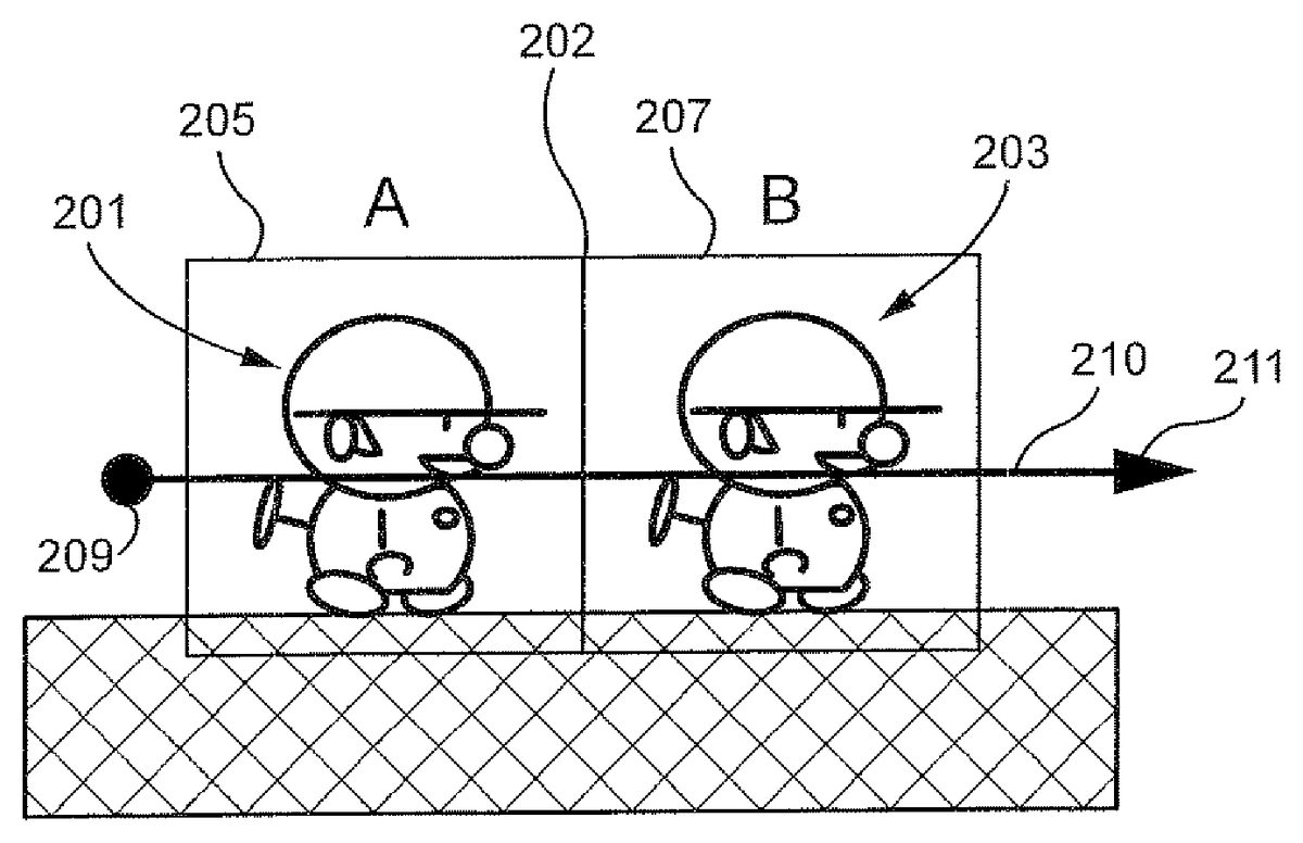
FIGS. 2A and 2Bshow an exemplary illustrative non-limiting implementation of two animated game characters or other objects201,203with associated stylus detection boxes205,207. In this example, stylus detection boxes205,207are adjacent one another, and used in conjunction with one another to control animated character movement.
In the scenario shown inFIGS. 2A and 2B, the game player wishes to cause both of animated characters201,203to begin moving to the right. To accomplish this result, the player can place the stylus down at a point209which is to the left of the left-most character201, and then draw a rightward stroke or gesture through both characters201,203along the path210as shown. In this instance, the stylus can have an initial position that is to the left of character201's stylus detection box205by a predetermined distance (e.g., 17 pixels or more from the centroid of character201and/or from the center of the character's associated stylus detection box205). Upon placing the stylus down at such a starting or “stylus down” position and moving it rightwards in contact with the touch screen through both characters201,203, both characters begin moving to the right in an animated fashion (seeFIG. 2B). The same situation could apply to move both characters leftward.
FIG. 3Ashows an exemplary representation of the same or different two animated game characters or other objects in a gamespace. Once again, first game character201is positioned to the left of a second game character203, and detection areas205,207of both game characters share an adjacent detection sidewall202in this example. In one exemplary illustrative non-limiting implementation, touch is placed at a point321on the screen within the leftmost character's201detection area205, but left of the centerline329of the character201(e.g., the vertical line dissecting the stylus detection box205associated with that character). In this implementation, the touch is at least a predetermined distance (e.g., 5 pixels or more) to the left of the centerline329of the character201. The touch is then moved along a rightward path326out of the leftmost character's201detection area205and through the rightmost character's203detection area207. This operation also causes both characters201,203to move in a rightward direction, as shown inFIG. 3Bby movement arrows323,325. Depending on a particular implementation, any suitable selection and action may result from applying the indicated stylus movements to characters in the indicated positions.
Moving Only One Character
Now suppose the game player wants only the rightmost character to begin moving to the right.FIG. 4Ashows another exemplary representation of the same or different two game characters in a gamespace. The first game character201is positioned to the left of a second game character203, and detection areas205,207of both game characters share an adjacent detection sidewall202. In this further exemplary illustrative non-limiting implementation, touch is placed at a point431on the screen within the leftmost character's201detection area205, but at least a certain distance (e.g., 5 pixels or more) to the right of the centerline439of the character201. The touch is then moved along a rightward path432out of detection area205and through detection area207. This operation causes the rightmost character203to move in a rightward direction, as shown inFIG. 4Bby movement arrow437. However, the leftmost character remains in its previous position as shown by the no-action (“no change”) symbol435. Depending on a particular implementation, any suitable selection and action may result from applying the indicated touch movements to characters in the indicated positions. Note that in the exemplary illustrative implementation, stylus detection begins from the centerline of the bounding boxes203,205to provide reliable detection if bounding box size changes.
FIG. 5Ashows another example of two game characters in a gamespace that are more closely spaced than in theFIG. 4A,4B example. A first game character201is positioned to the left of a second game character203, but detection areas205,207of the two game characters overlap to create an overlap area542(in this particular example, the characters are not close enough to one another to create a collision detection situation). In a further exemplary illustrative non-limiting implementation, touch is placed at a point541on the screen within the overlap area542, making the starting point within both detection areas205,207. In this implementation, although the touch is in the overlap area542, if the initial point541is closer to the centerline543of the rightmost character203than the centerline544of the leftmost character201, and the touch is then moved along a rightward path546out of detection area205and through detection area207, this operation causes only the rightmost character203to move in a rightward direction, as shown inFIG. 5Bby movement arrow549. The leftmost character remains in its previous position as shown by the no-action symbol547. Depending on a particular implementation, any suitable selection and action may result from applying the indicated touch movements to characters in the indicated positions.
Now suppose the game player wants to cause the leftmost character to begin moving to the left.FIG. 6Ashows another exemplary representation of two game characters in a gamespace. A first game character201is positioned to the left of a second game character203, and detection areas205,207of both game characters overlap creating an overlap area652. In this further exemplary illustrative non-limiting implementation, touch is placed at a point651on the screen within the overlap area652, making the starting point within both detection areas205,207. In this implementation, although the touch is in the overlap area652, assume the initial point651is closer to the centerline659of the leftmost character201than the centerline658of the rightmost character203. If the touch is then moved along a leftward path654out of detection area207and through detection area205to a point653left of the leftmost character's201detection area205, this operation causes the leftmost character201to flip left and begin moving in a leftward direction, as shown inFIG. 6Bby movement arrow655. The rightmost character remains in its previous position or state (e.g., stopped or moving to the right) as shown by the no-change symbol657. Depending on a particular implementation, any suitable selection and action may result from applying the indicated touch movements to characters in the indicated positions.
Suppose now the game player again wants to cause only the rightmost character to move to the right.FIG. 7Ashows another exemplary representation of two game characters in a gamespace. A first game character201is positioned to the left of a second game character203, and detection areas205,207do not contact one another. In this further exemplary illustrative non-limiting implementation, touch is placed at a point761on the screen within the leftmost character's201detection area205. The point761, however, is outside the area768defined between the centerline762and a predetermined position764(e.g., more than 5 pixels to the right). The touch is then moved along a rightward path766out of detection area205and through detection area207to a point763right of the rightmost character's203detection area207. This operation causes the rightmost character203to begin moving in a rightward direction, as shown inFIG. 7Bby movement arrow767. The leftmost character remains in its previous position or state as shown by the no-action symbol765. Depending on a particular implementation, any suitable selection and action may result from applying the indicated stylus movements to characters in the indicated positions.
FIG. 8Ashows another exemplary representation of two game characters in a gamespace. A first game character201is positioned to the left of a second game character203, but detection areas205,207do not contact one other. In this further exemplary illustrative non-limiting implementation, a stylus is placed at a point871on the screen within the leftmost character's201detection area205. The point871is left of the leftmost character's201centerline872by at least a predetermined distance (e.g., 5 pixels or more). The touch is then moved along a rightward path876out of detection area205and into detection area207to a point873left of the rightmost character's203centerline874. In this implementation, as long as the stylus stops at a point873at least a predetermined distance (e.g., 5 pixels or more) to the left of the rightmost character's203centerline874, then this operation causes only the leftmost character201to move in a rightward direction, as shown inFIG. 8Bby movement arrow875. The rightmost character remains in its previous position as shown by the no action symbol877. Additionally, if the leftmost character201collides with the rightmost character203, both characters201,203may flip to face left and continue their movement. Alternatively, if the stroke is not stopped at least a predetermined distance (e.g., 5 pixels to the left) from the rightmost character's203centerline874, the rightmost character may also be moved in the rightwards direction but instead stops a predetermined distance (e.g., 5 pixels) to the right of the rightmost character's centerline874, then both characters201,203may move to the right in tandem. Depending on a particular implementation, any suitable selection and action may result from applying the indicated stylus movements to characters in the indicated positions.
Exemplary Illustrative Non-Limiting Flowchart
FIG. 9shows a flowchart detailing an exemplary illustrative non-limiting process for object selection and movement. Subroutine A981loops at a detection step983until a first “stylus down” or “stylus resting” point is detected. Then, at a first selection step985, the subroutine determines whether at least one object should be selected based on the position of the first point. As explained above, in one non-limiting exemplary implementation, an object will be selected based on the position of the first point if the first point is within a certain proximity to a line dividing the object down the center.
If one or more objects are to be selected based on the first point, the subroutine selects them at a second selection step987. Whether or not objects are selected, the subroutine next loops until stylus movement is detected at a movement detection step989. Based on the movement, objects may be selected, so the subroutine checks to see if objects need to be selected in a third selection step991. In a further non-limiting exemplary implementation, an object will be selected if the path of the stylus crosses the centerline of the object.
If objects are to be selected based on the path of the movement of the stylus, the subroutine then selects the one or more objects to be selected in fourth selection step993. Whether or not objects were selected in step993, the subroutine, in a movement step995, then moves all selected objects in a direction determined based on the movement of the stylus
While the technology herein has been described in terms of exemplary illustrative non-limiting implementations, it is understood that these implementations are provided by way of example only. For example, while a stylus contacting a touch screen is described above, strokes made using any other means (e.g., a finger on a touch pad, a handheld controller motion or a light pen tracing a path on a television screen, etc.) are also possible. While all the previous non-limiting exemplary implementations have been described with character orientation and movement in a particular direction, the directions may vary in different implementations. The invention is to be defined by the scope of the claims.
Claims
- A method of allowing a human user to control movement of plural displayed animated characters displayed on a display screen of a computing device in response to gestures manually inputted by a human player, the portable computing device comprising a CPU core connected to a memory, a display controller between the CPU core and the display screen, and an input/output controller connected to the CPU core, the method comprising: displaying at least first and second animated characters at respective display positions on a touch sensitive display;detecting a single gesture traced on the touch sensitive display by a human user;and selecting, in response to said single gesture, whether to control said first and second animated characters to move individually or in tandem, including selecting individual movement of the first and second animated characters in response to a detected first single gesture tracing a first path relative to display positions of said displayed first and second animated characters, and selecting tandem movement of the first and second animated characters in response to a detected second single gesture tracing a second path relative to display positions of said displayed first and second animated characters that is distinguishable from the first path relative to display positions of said displayed first and second animated characters;conditioning the selecting based on the starting position of the detected gesture path relative to the display positions of the first and second animated characters;selecting movement direction of the selected animated character(s) based on direction of the detected gesture path;and moving the displayed first and second animated characters on the touch sensitive display individually or in tandem in the selected movement direction at least in part in accordance with the selection of individual or tandem movement.
- The method of claim 1 further including selecting whether to flip the orientation of the first character in response to the detected gesture path before or during movement of the first character.
- The method of claim 1 further including playing a video game using the first and second characters.
- The method of claim 1 further including selecting whether to control the first and second characters to move in a common direction in response to the detected gesture path.
- The method of claim 1 further including maintaining a spacing between the first and second characters as they move individually or in tandem.
- The method of claim 1 further including selecting whether to control the first and second characters to move individually or as a group in response to the detected gesture.
- The method of claim 1 further including selecting whether to control the first and second characters to move in different directions in response to the detected gesture path.
- The method of claim 1 further including selecting the second game character for movement in response to collision between the first and second game characters.
Disclaimer: Data collected from the USPTO and may be malformed, incomplete, and/or otherwise inaccurate.