U.S. Pat. No. 8,142,286
PROGRAMMABLE MOVEMENT OF AN ORIENTATION OF A GAME CHARACTER VIEW OF A GAME ENVIRONMENT
AssigneeMicrosoft Corporation
Issue DateAugust 17, 2007
Illustrative Figure
Abstract
A control system comprises a control device comprising a programmable macro button, a memory containing view change settings, a driver program and a microprocessor. The driver program includes a view change output that is produced in response to actuation of the macro button and is based on the view change settings. The microprocessor is configured to move the orientation of the character view of the game environment from a beginning orientation to an ending orientation in response to the view change output. Also disclosed is a method of using a control system to move an orientation of a character view of a game environment in a video game.
Description
DETAILED DESCRIPTION FIG. 1is a simplified block diagram of an exemplary game system100in accordance with embodiments. The game system comprises a video game application102stored in memory104A, a display106and a control system108. The control system108includes a control device110, a driver program112stored in memory104B, view change settings114stored in memory104C and a microprocessor or central processing unit116. The microprocessor116represents one or more devices that are configured to control the operations of the game system100and the control system108. The microprocessor116may be a component of a personal computer, a game console (e.g., Xbox 360) or other computing device. Exemplary operations that could be performed by the microprocessor116include data communications in the system100including data communications with accessible memory of the system, such as memory104A,104B and104C; network data communications; responses to input signals118received from one or more of the control devices110; the execution of instructions stored on a tangible medium, such as the instructions of the video game application102and the driver program112; the generation of output signals that control one or more output devices, such as a display signal120that controls the display106; and other functions. The memories104A-C represent physical storage mediums that can be separate from each other or combined. The physical storage mediums104A-C can take on many different forms, such as CD-ROM's, digital versatile disks (DVD) or other optical disk storage media, flash memory drives, hard drives, RAM, ROM, EEPROM, magnetic cassettes, magnetic tape, magnetic disk storage or other magnetic storage devices, or any other medium which can be used to store the desired video game application102, driver program112and the view change settings114. The control device110may be any suitable input device to the control system108for controlling operations of a game character within the game environment of the video game. Embodiments of the control device110include a computer mouse122, a game controller (i.e., a control device that is ...
DETAILED DESCRIPTION
FIG. 1is a simplified block diagram of an exemplary game system100in accordance with embodiments. The game system comprises a video game application102stored in memory104A, a display106and a control system108. The control system108includes a control device110, a driver program112stored in memory104B, view change settings114stored in memory104C and a microprocessor or central processing unit116.
The microprocessor116represents one or more devices that are configured to control the operations of the game system100and the control system108. The microprocessor116may be a component of a personal computer, a game console (e.g., Xbox 360) or other computing device. Exemplary operations that could be performed by the microprocessor116include data communications in the system100including data communications with accessible memory of the system, such as memory104A,104B and104C; network data communications; responses to input signals118received from one or more of the control devices110; the execution of instructions stored on a tangible medium, such as the instructions of the video game application102and the driver program112; the generation of output signals that control one or more output devices, such as a display signal120that controls the display106; and other functions.
The memories104A-C represent physical storage mediums that can be separate from each other or combined. The physical storage mediums104A-C can take on many different forms, such as CD-ROM's, digital versatile disks (DVD) or other optical disk storage media, flash memory drives, hard drives, RAM, ROM, EEPROM, magnetic cassettes, magnetic tape, magnetic disk storage or other magnetic storage devices, or any other medium which can be used to store the desired video game application102, driver program112and the view change settings114.
The control device110may be any suitable input device to the control system108for controlling operations of a game character within the game environment of the video game. Embodiments of the control device110include a computer mouse122, a game controller (i.e., a control device that is generally dedicated to gaming)124and a keyboard126, which are respectively illustrated inFIGS. 2-4. The control device110includes control components128(FIG. 1) that, when actuated, generate the input signals118. The driver program112translates the input signals118into information that is used by the video game application102under the control of the microprocessor116to produce an action within the video game, such as movement of the game character or other action.
Exemplary control components128of the mouse122include buttons132, a scroll wheel134, the mechanical or optical components (not shown) that translate lateral or side-to-side movement of the mouse into movement of the game character, and other components. Exemplary control components128of the game controller124include buttons136, a directional pad138, a joystick140, finger triggers (not shown) and other components. Exemplary control components128of the keyboard126include the keys142, such as the arrow keys142A-D, and other components.
As discussed above, the video game application102assigns predefined actions to the control components128of the control device110. The actuation of some of the control components128results in the execution of the predefined action of the game character, such as a jump or a kick, for example. Other movements of the game character in response to actuation of some of the control components128include operator or player controlled movements that do not fall into this predefined action category, such as the orientation of the game character's view and the direction and speed at which the game character travels.
The video game application102can comprise any game in which embodiments are useful. Exemplary video games include first-person games (e.g., Halo®, racing games), in which the display106presents the player (i.e., the operator of the control device) a view of the game environment as seen by the game character (i.e., human, creature, mechanical device, etc.) he or she controls, and third-person games (e.g., role playing games such as Dungeon Siege® II), in which the display106presents a distant view of the game character within the game environment. Whether the video game provides a first-person display of the game environment or a third-person display of the game environment, the game character has a view (hereinafter “character view”), which has a particular orientation.
FIG. 5illustrates an exemplary view of a portion of a game character144within a game environment146as produced by the execution of the video game application102. When the game application102produces a first-person video game, the display106presents the view of the game environment146as seen by the game character144, which is represented by the projection148. Objects within the projection148that are viewable to the game character144are provided on the display106of the game system100. Thus, the orientation of the character view144determines what the player sees on the display106.
When the video game application102produces a third-person game, the display106presents the game character144(only a portion shown) and the surrounding game environment146. The third-person game character144has a “view” of the game environment corresponding to the orientation of the game character's “head” or “eyes”, for example. Thus, movements of the head of the third-person game character144results in a movement of the orientation of the game character view.
The movement of the orientation of the third-person game character view can be important in, for example, role playing games where the game character144can interact with other objects and inhabitants of the game environment146. Typically, the interaction between the game character144and an object or inhabitant of the game environment146is driven, in part, by the orientation of the character view or where the game character is “looking”.
As mentioned above, the orientation of the first-person or third-person character view of the game environment146, represented by the arrow150inFIG. 5, can generally be moved using one of the control components128of the control device110. In most games, the orientation150of the character view can rotate about a vertical axis152in clockwise and counterclockwise directions, as indicated by the arrow154shown in the simplified top plan view of the game character144inFIG. 6. Thus, the orientation150may move from a starting orientation156to an ending orientation158by rotating the orientation150about the vertical axis152in the counterclockwise direction indicated by arrow160, or the clockwise direction.
Additionally, the orientation150of the character view may also pivot upward and downward about an axis162, as represented by the arrow164in the simplified side view of the game character144shown inFIG. 7. Thus, the orientation150may move from a starting orientation166to an ending orientation168by pivoting the orientation150about the vertical axis152in the upward direction indicated by arrow170, as shown inFIG. 6.
The movements of the orientation150of the character view may also include both the rotation about the vertical axis152and the pivoting about the axis162in response to the actuation of one or more of the control components128of the device110.
When the control device110is a computer mouse, such as mouse122shown inFIG. 2, the orientation150of the game character's view can be rotated about the vertical axis152and/or pivoted up or down about the axis162in response to movements of the mouse across a surface171. For instance, movement of the mouse122across the surface171in the directions indicated by arrow172can cause the orientation of the character view to rotate about the axis152in either a clockwise or counterclockwise direction. Similarly, movement of the mouse122across the surface171in the direction indicated by arrow174can cause the orientation150of the character view to pivot upward or downward.
When the controller is a game controller, such as game controller124shown inFIG. 3, the up, down, clockwise and counterclockwise movements of the orientation of the character view are typically performed in response to movements of the directional pad138or the joystick140, for example.
When the control device110is a keyboard, such as the keyboard126shown inFIG. 4, the up, down, clockwise and counterclockwise movements of the orientation150of the character view are performed in response to actuation of separate keys142, such as the arrow keys142A-D, for example.
The signals118produced by the control device110in response to actuations of the control components128that result in movements of the orientation150of the character view generally provide distance and direction information to the driver program112in accordance with conventional methods. The distance and direction information generally comprises a linear count of distance units in the given direction over a unit of time. The driver program112translates the distance and direction information from the signals118into movement information184(FIG. 1) that is used by the microprocessor116to move the orientation150in the indicated direction in accordance with the video game application102. For example, when the signals118indicate a movement of 20 units of distance in a given direction, the driver program112translates the signals118such that they can be processed to produce a corresponding rotational movement of the orientation150of the character view about the one of the axes152and162in accordance with the video game application102.
When the control component128is a button, such as an arrow button142A-D of the keyboard126(FIG. 4), the signals118produced in response to actuation of the key indicate movement in the given direction, a distance and speed of which is based on each strike of the key and/or the duration of time that the key is pressed. Thus, for example, 5 strikes of the key over a period of one second, or depressing and holding the key for 1 second, may each constitute 5 units of distance to the driver program112. That distance and speed is then communicated to the microprocessor116which rotates the orientation150about the corresponding axis152or162in accordance with the video game application102.
When the control component128corresponds to the components of the mouse122that detect travel of the mouse across the surface171, the signals118produced in response to such movement of the mouse122indicate distances traveled in the directions170or174in which the mouse122is moved. The signals118also provide speed information based on the distance traveled by the mouse122per unit of time. Each unit of distance the mouse122travels in a given direction170or174is translated by the driver program112into the movement information184that moves the orientation150of the character view, as presented on the display106, an amount and direction as determined by the video game application102.
When the control component128is a directional pad138or a joystick140of the game controller124, the signals118generally indicate a direction in which the pad138or joystick140is deflected. The amount of the deflection from the quiescent state of the pad138or joystick140can be used to indicate a speed of the desired movement. The driver program112translates the direction, distance and speed of movement indicated by the signals118and provides the resultant movement information184to the microprocessor116, which operates to move the orientation150in accordance with the video game application102.
Embodiments are directed to systems, such as control system108, and methods for allowing a player to calibrate a desired operator-controlled movement of the orientation150of the game character view and assign the calibrated movement to a macro button180(FIG. 1) of the control device110. The calibrated movement is stored by the view change settings114. Actuation of the macro button180then produces the calibrated movement of the orientation150of the game character view based on the view change settings114. Accordingly, embodiments allow a player to actuate the macro button180to perform a rotation of the orientation150of the character view about the vertical axis152(FIG. 6), the horizontal axis162(FIG. 7), or both the vertical and horizontal axes152and162. For example, rather than having to move the mouse122across the surface171, pressing a button or key for a period of time or a select number of times, or moving a directional pad138or joystick140in a given direction for a period of time, the operator only needs to press the macro button180to execute the player-operated movement of the orientation150as defined by the view change settings114.
One advantage of this “quick turn” feature is that it reduces the complexity of the controls for the video game by eliminating the need to use the control components128to execute a desired movement of the orientation150. For instance, in fast-paced first-person “shooter” video games, the player must constantly be looking for predator game characters in the game environment including performing180degree turns about the vertical axis152to see if anyone is lurking behind the game character144. Embodiments allow the player to set the view change settings114such that the game character144performs the desired 180 degree turn of the orientation150in response to actuation of the macro button180. The use of the macro button180thus frees the player from having to concentrate on making the desired 180 degree rotational movement of the orientation150using the control components128of the control device110.
Thus, in one embodiment of the control system108, the control device110includes the macro button180. Actuation of the macro button180produces a macro actuation signal182(FIG. 1). The macro button180is distinct from the control components128that are programmed for use during play of the video game application102. The driver program112produces a view change output184(i.e., movement information) in response to the actuation of the macro button180and reception of the macro actuation signal182. The view change output184is based on the view change settings114stored in the memory104C. The microprocessor116is configured to move the orientation150of the character view of the gaming environment146from a beginning orientation186to an ending orientation188based on the view change settings114in response to the view change output184, as illustrated in the simplified plan view of a game character144provided inFIG. 8. As used herein, the view change output184, which is based on the view change settings114, mirrors the signal or information that would have been generated by the driver program112in response to the actuation of the control components128of the control device110that the player would have performed in order to move the orientation150from the beginning orientation186to the ending orientation188. Thus, the amount and direction that the orientation150moves in response to the actuation of the macro button180is determined, at least in part, by the view change settings114. Additional embodiments of the control system108will be described in combination with embodiments of the method illustrated inFIG. 9.
FIG. 9is a flowchart illustrating a method of using a control system, such as control system108, to move an orientation150of a character view of a gaming environment146in a video game, in accordance with embodiments. The method steps are generally performed in response to execution of instructions of the driver program112and the video game application102respectively stored in the tangible mediums represented by memories104B and104A, respectively, by the microprocessor116.
At step200, a view orientation move is calibrated including storing the view change settings114in memory104C (FIG. 1). Next, at step202, the view change output184is produced in response to the actuation of the macro button180or reception of the actuation output signal182. The orientation150of the character view of the gaming environment146is moved, at step204, from the beginning orientation186to the ending orientation188based on the view change settings114in response to the view change output184, as mentioned above and illustrated in the simplified plan view of a game character144provided inFIG. 8. The movement of the orientation150is generally a rotation about an axis210, as indicated by arrow211. The direction of the rotation is determined by the view change settings114.
In one embodiment, the beginning orientation186corresponds to the orientation150of the character view during game play when the macro button180is actuated. The orientation150then moves to the ending orientation188, based on the view change settings114, during play of the video game102.
In order to simplify the discussion of the embodiments, the movement of the orientation150in accordance with embodiments will be described with reference to rotations about a single axis210, shown inFIG. 8. The axis210represents one or more axes about which the control components128of the control device110are configured to rotate the orientation150of the character view. Thus, the movements described below may alternatively involve a rotation about the horizontal axis162alone, or simultaneous rotations about the vertical and horizontal axes152and162, based on the signals118produced by the control device110, for example. Accordingly, in one embodiment of step204, the axis210represents a single axis, which may correspond to the vertical axis152(FIG. 6) or the horizontal axis162(FIG. 7), about which the orientation150moves (i.e., rotates) from the beginning orientation186to the ending orientation188during step204based on the view change settings114. In another embodiment, the axis210represents a combination of the vertical and the horizontal axes152and162, and the orientation150moves or rotates from the beginning orientation186to the ending orientation188about the axis210during step204.
One embodiment of the calibrating step200is illustrated in the flowchart ofFIG. 10. At step212the calibration routine is started. In one embodiment, the calibration routine is started by pressing and holding the macro button180and, after a predetermined period of time, releasing the macro button180. In one embodiment, the predetermined period of time is approximately one second or more.
In one embodiment, the calibration routine is started during play of the video game102. Upon starting the calibration routine, the orientation150of the character view has a beginning orientation214, shown inFIG. 11.
At step214, the orientation150of the character view is moved from a beginning orientation216to an ending orientation218about an axis220as indicated by arrow221during play of the video game102, as illustrated inFIG. 11. As discussed above with regard to axis210, axis220can represent one or more axes about which the control components128of the control device110are configured to rotate the orientation150of the character view.
In one embodiment, the movement of the orientation150of the character view in step214comprises adjusting the orientation150of the character view using a control component128of the control device110that are generally pre-set to perform the desired movement of the orientation150during play of the video game102. Thus, the movement of the orientation150of the character view is performed without the use of the macro button180.
When the control device110is in the form of a computer mouse122(FIG. 2), the step214can be performed using the control components128that are traditionally used to move the orientation150of the character view. For instance, the movement of the orientation150can be performed by moving the mouse122across the surface171in the direction indicated by arrow170and/or174to move the orientation150of the character view during play of the video game102from the beginning orientation216to the ending orientation218, as described above. Other embodiments include moving the orientation from the beginning orientation216to the ending orientation218using a game controller124(FIG. 3) or a keyboard126(FIG. 4), as described above.
At step222, the calibration routine is ended. The ending orientation218corresponds to the orientation150of the character view upon ending the calibration routine. In one embodiment, the calibration routine is ended by actuating the macro button180.
At step224, the view change settings114are produced based on the movement of the orientation150of the character view in step214and the view change settings are stored in the memory104C at step226. In one embodiment, the view change settings114based on a difference between the beginning orientation216and the ending orientation218. Because the distance and direction information provided by the signals118of the control device110that correspond to movement of the orientation150are generally a linear count of distances units in the given direction over a unit of time, the difference between the first and second orientations can be obtained by simply subtracting the position value of the first orientation from the position value of the second orientation. The sign of the resulting difference indicates the direction in which the orientation150was moved. For instance, the beginning orientation216and the ending orientation218may have a set angular position relative to a reference228. In that case, the difference between the beginning and ending orientations216and218is equal to the angular position of the ending orientation218relative to the reference228less the angular position of the beginning orientation216relative to the reference228.
In one embodiment, the movement of the orientation150in step204following actuation of the macro button180matches the movement of the orientation150during the moving step214. That is the view change settings114are set to rotate the orientation150from the beginning orientation186in response to actuation of the macro button180by an amount that matches the difference between the beginning and ending orientations216and218set during the calibration routine.
In one embodiment of step214, the player uses the control component128of the control device110to move the orientation150of the character view about the vertical axis152approximately 360. This is helpful when it is desired to have the view change settings114indicate 180 degrees and other specific angular turns. For instance, during play of a first-person video game, it may be desired to program the macro button180to perform a 180 degree turn to allow the game character144to quick take a look behind him or her. However, the game environment146, in which the game character144resides, may make it difficult to determine with any real precision a 180 degree turn from the beginning orientation216of the calibration routine. By having the player move the orientation150a full 360 degrees from the beginning orientation216of the calibration routine, the view change settings114can be set to one half the measured movement during the calibration routine to more precisely set the desired 180 degree turn.
In accordance with another embodiment, the view change settings114are set such that the movement of the orientation150in the moving step204does not match the difference between the beginning and ending orientations216and218set during the calibration routine. In one embodiment, the view change settings114are set such that the orientation150moves a fraction of the difference between the beginning and ending orientations216and218set during the calibration routine. Embodiments of the fraction include one-fourth, one-half and three-fourths of the difference between the beginning and ending orientations216and218.
In one embodiment, the view change settings114are configured to move the orientation150one-half of the difference between the beginning and ending orientations216and218achieved during the moving step214. This embodiment is particularly useful when it is desired to set the quick turn feature to execute a 180 degree turn upon actuation of the macro button180when it is difficult to know the degree to which the orientation150of the character view of the game character144has rotated from the beginning position216during the moving step214. In accordance with this embodiment, the player rotates the orientation150of the character view a full 360 degrees during play of the video game102(hereinafter “360 degree calibration”), such that the beginning and ending orientations216and218are approximately aligned with each other, as illustrated inFIG. 12. The view change settings114are then set to move the orientation150from the beginning position186approximately 180 degrees about the axis210to the ending position188during the moving step204upon actuation of the macro button180, as illustrated inFIG. 8.
In accordance with another embodiment, following the 360 degree calibration, the view change settings114produced in step224are configured to move the orientation150from the beginning orientation186one quarter of the 360 degree calibrated turn or approximately 90 degrees to the ending orientation188during the moving step204. This quarter turn allows the player to take a quick look to the side through actuation of the macro button180.
In yet another embodiment, following the 360 degree calibration, the view change settings114produced in step224are configured to move the orientation150from the beginning orientation186three quarters or approximately 270 degrees to the ending orientation188during the moving step204. This three quarter turn allows the player to look to the opposite side of the game player144than that produced by the above-described quarter turn. Alternatively, this three quarter turn can be accomplished using the one quarter turn values for the view change settings114, but with a change in the designated direction, such that the view150is moved in the opposite direction than that of the quarter turn described above.
In one embodiment of the method illustrated inFIG. 8, the orientation150of the character view is moved from the ending orientation188to the beginning orientation186, at step230. This generally occurs in response to a view return output contained in the movement information184that is generated by the driver program112. As used herein, the view change output184generally mirrors the movement information184that would have been generated by the driver program112in response to the actuation of the control components128of the control device110that the player would have performed in order to move the orientation150from the ending orientation188to the beginning orientation186.
In one embodiment, the view change output184is generated in response to a subsequent actuation of the macro button180. That is, following a first actuation of the macro button180, which triggers the moving step204, a second actuation of the macro button180triggers the moving step230and the microprocessor116moves the orientation150from the ending orientation188to the beginning orientation186.
In accordance with another embodiment, the view change output184is generated automatically by the driver program112after a predetermined period of time following the moving step204. Thus, after the player initially actuates the macro button180, the orientation150moves from the beginning orientation186to the ending orientation188. Then, after the predetermined period of time, the microprocessor116moves the orientation150from the ending orientation188back to the beginning orientation186.
In one embodiment, the actuation of the macro button180to trigger the moving step204comprises pressing and holding the macro button180. That is, the pressing and holding of the macro button180causes the production of the view change output (movement information184), which in turn causes the microprocessor116to move the orientation150from the beginning orientation186to the ending orientation188. While the macro button180is held, the orientation150remains substantially in the ending orientation188, unless possibly adjusted through actuation of one of the control components128of the control device110. The release of the macro button180causes the driver program112to produce the view return output (movement information184) and the microprocessor116responds by moving the orientation150from the ending orientation188to the beginning orientation186, in accordance with step230.
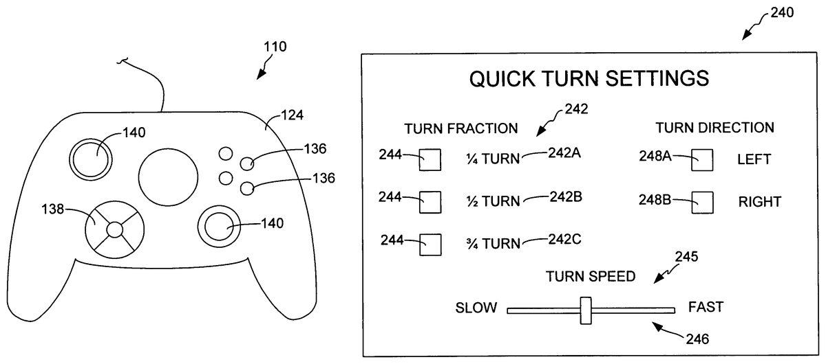
In accordance with one embodiment, the driver program112comprises instructions executable by the microprocessor116to generate a graphical user interface, which can be used by the player to configure the quick turn settings.FIG. 13is a simplified diagram of a graphical user interface240in accordance with various embodiments. One embodiment of the interface240includes turn fraction settings242. One embodiment of the turn fraction settings242includes one or more fractions of quick turn that was calibrated during the calibrating step200(FIG. 9). Exemplary embodiments of the fractions include a one quarter turn242A, a one half turn242B, and a three quarters turn242C. The user may select the desired turn fraction setting242by selecting the box244adjacent the desired turn. For example, the player performs a 360 degree calibration turn during the calibrating step200, the player can quickly select whether the quick turn (step204) that is executed in response to actuation of the macro button180will be a 90 degree turn, a 180 degree turn, or a 270 degree turn by selecting the corresponding box244in the interface240.
In accordance with another embodiment, the speed at which the quick turn (step204) is executed is automatically set to the speed at which it was performed by the player during the calibration routine (step200). In another embodiment, the speed at which the quick turn (step204) is executed is automatically set to a predefined value.
In yet another embodiment, the speed at which the quick turn (step204) is execute is user-selectable. In one embodiment, the graphical user interface240includes a turn speed setting245where the user may select the desired speed at which the quick turn is performed. In one embodiment, the turn speed setting245comprises a slide bar246that is adjustable between slow and fast speed settings. Other embodiments include the display of discrete speed settings, such as “slow”, “normal” and “fast” (not shown).
In accordance with another embodiment of the invention, the user may select a direction in which the quick turn is performed about the axis210(FIG. 8). In one embodiment, the direction options are provided in the graphical user interface240where the user may select the quick turn to be performed to the left or counterclockwise direction by selecting box248A or to the right or clockwise direction by selecting box248B.
In accordance with one embodiment, the control device110includes a plurality of macro buttons, such as macro button180and macro button250, shown inFIG. 1. Each of the macro buttons generally operates in accordance with the embodiments described above.
In one embodiment, the macro buttons180and250comprise a macro button pair, in which the actuation of the macro button180results in the quick turn (steps202and204) to be performed in the clockwise direction about the axis210(FIG. 8) and the actuation of the macro button250results in the quick turn to be performed in the counterclockwise direction about the axis210.
In one embodiment, the scroll wheel134of the mouse122(FIG. 2) operates as a tilt wheel in which it can be moved either left or right, as indicated by arrow252, about an axis that is approximately in line with arrow174. The movement of the wheel134to the left actuates an interior button254and movement of the wheel134to the right actuates an interior button256. In one embodiment, the interior buttons254and256are designated as a macro button pair. Actuation of the left button254triggers the quick turn (steps202and204) to move the orientation150from the beginning orientation186to the ending orientation188in one direction (e.g., left) while the actuation of the right button256triggers the quick turn to move the orientation150from the beginning orientation186to the ending orientation188in the opposite direction (e.g., right).
Although the subject matter has been described in language specific to structural features and/or methodological acts, it is to be understood that the subject matter defined in the appended claims is not necessarily limited to the specific features or acts described above. Rather, the specific features and acts described above are disclosed as example forms of implementing the claims.
Claims
- A control system for use in combination with a video game presented on a display, the video game including a character having a character view of a game environment, the character view having an orientation, the system comprising: a control device comprising an input mechanism and a selectively reprogrammable macro button, the input mechanism and the selectively reprogrammable macro button being different components of the control device, the input mechanism enabling an end user of the control device to move the orientation of the character view from a beginning orientation to an ending orientation through a manipulation of the input mechanism;a reprogrammable memory that stores a difference between the beginning orientation and the ending orientation as a view change setting, the view change setting including a direction of rotation and an amount of rotation;a driver program having a view change output that is produced in response to an actuation of the macro button;and a microprocessor that moves the orientation of the character view of the game environment in response to the view change output, the orientation of the character view being moved in the same direction of rotation and by the same amount of rotation as stored in the view change setting.
- The system of claim 1 , wherein the view change setting corresponds to rotation about two different rotational axes.
- The system of claim 1 , wherein the input mechanism comprises instructions stored in a tangible medium and executable by the microprocessor to perform a series of steps that include: making a record of a series of changes in the orientation of the character view while the series of changes are being made during play of the video game;and storing the record of the series of changes in the reprogrammable memory as the view change setting.
- The system of claim 1 , wherein: the driver program automatically produces a view return output after a determined expiration of a predetermined period of time starting after said actuation of the macro button;and the microprocessor responds to said production of the view return output by automatically moving the orientation of the character view.
- The system of claim 1 , wherein: the driver program automatically produces a view return output in response to a subsequent actuation of the macro button;and the microprocessor responds to said production of the view return output by automatically moving the orientation of the character view.
- The system of claim 1 , wherein: said actuation of the macro button comprises pressing the macro button and holding it in a pressed down position;the driver program produces a view return output in response to a release of the macro button out of the pressed down position;and the microprocessor responds to the view return output by automatically moving the orientation of the character view in response to the view return output.
- The system of claim 1 , wherein the control device comprises a computer mouse.
- The system of claim 7 , wherein the macro button comprises a tilt wheel.
- The system of claim 1 , wherein the control device is selected from the group consisting of a keyboard and a game controller.
- A method of using a control system to move an orientation of a character view of a game environment in a video game, the method comprising: moving a control input mechanism of a control device along multiple axes of rotation to selectively calibrate a view orientation move;determining a direction of rotation and an amount of rotation associated with the view orientation move for each of the multiple axes of rotation;storing the directions of rotation and the amounts of rotation in a memory as a view change setting;producing a view change output in response to an actuation of a macro button of the control device;and responding to the view change output by moving the orientation of the character view of the game environment in the directions of rotation and by the amounts of rotation as defined within the view change setting.
- The method of claim 10 , wherein selectively calibrating the view orientation move further comprises: starting a calibration routine;adjusting the orientation of the character view during play of the video game;ending the calibration routine;and producing the view change setting based on the movement of the orientation of the character view during the calibration routine.
- The method of claim 11 , wherein starting the calibration routine comprises pressing and holding the macro button and, after a predetermined period of time, releasing the macro button.
- The method of claim 12 , wherein ending the calibration routine comprises actuating the macro button.
- The method of claim 11 , wherein: the control device comprises a computer mouse;and adjusting the orientation of the character view comprises moving the mouse across a surface.
- The method of claim 11 , wherein: the orientation of the character view is based on a game character's head orientation;and the view change setting corresponds to a change in the head orientation;and moving the orientation of the character view of the game environment comprises moving the head orientation of the character.
- The method of claim 10 , wherein the amount of rotation about at least one of the multiple axes of rotation is greater than ninety degrees.
- The method of claim 10 , and further comprising: automatically returning the orientation of the character view of the game environment to the previous orientation after a predetermined period of time.
- The method of claim 10 , and further comprising: returning the orientation of the character view of the game environment to the previous orientation in response to a subsequent actuation of the macro button.
- A control system for use in combination with a video game including a character view of a game environment having an orientation, the system comprising: a control device comprising a macro button;a memory;a microprocessor;and a driver program comprising instructions stored in a tangible medium and executable by the microprocessor to perform steps of: generating a user interface that enables an end user of the control device to select a speed, a direction, and a fraction of a rotation for a view change setting;storing the view change setting in the memory;and moving the orientation of the character view of the game environment from a beginning orientation to an ending orientation based on the view change setting in response to an actuation of the macro button.
Disclaimer: Data collected from the USPTO and may be malformed, incomplete, and/or otherwise inaccurate.