U.S. Pat. No. 8,125,487
GAME CONSOLE SYSTEM CAPABLE OF PARALLELING THE OPERATION OF MULTIPLE GRAPHICS PROCESSING UNITS (GPUS) EMPLOYING A GRAPHICS HUB DEVICE SUPPORTED ON A GAME CONSOLE BOARD
AssigneeLucid Information Technology, Ltd
Issue DateSeptember 26, 2007
Illustrative Figure
Abstract
A game console system capable of parallelizing the operation of multiple graphics processing units (GPUs) supported on game console board, using a graphics hub device, and a multi-mode parallel graphics rendering subsystem supporting multiple modes of parallel operation and having software and hardware implemented components. The game console system includes (i) CPU memory space for storing one or more graphics-based applications, (ii) one or more CPUs for executing the graphics-based applications, (iii) a plurality of graphic processing pipelines (GPPLs), implemented using the GPUs, and (iv) an automatic mode control module. During the run-time of the graphics-based application, the automatic mode control module automatically controls the mode of parallel operation of the multi-mode parallel graphics rendering subsystem so that the GPUs are driven in a parallelized manner.
Description
DETAILED DESCRIPTION OF THE ILLUSTRATIVE EMBODIMENTS OF THE PRESENT INVENTION Referring now toFIGS. 4A through 12Bin the accompanying Drawings, the various illustrative embodiments of the Multi-Mode Parallel Graphics Rendering System (MMPGRS) and Multi-Mode Parallel Graphics Rendering Process (MMPGRP) of the present invention will now be described in great technical detail, wherein like elements will be indicated using like reference numerals. In general, one aspect of the present invention teaches how to dynamically retain high and steady performance of a three-dimensional (3D) graphics system on conventional platforms (e.g. PCs, laptops, servers, etc.), as well as on silicon level graphics systems (e.g. graphics system on chip (SOC) implementations, integrated graphics device IGD implementations, and hybrid CPU/GPU die implementations). This aspect of the present invention is accomplished by means of a novel architecture supporting adaptive graphics parallelism having both software, hardware and hybrid embodiments. The MMPGRS and MMPGRP of the present invention fulfills a great need in the marketplace by providing a highly-suited parallelism scheme, By virtue of the present invention, different GPPL-based parallel rendering schemes, supported on the MMPGRS, dynamically alternate throughout the course of any particular graphics application running on the host system in which the MMPGRS is embodied, and adapting the optimal parallel rendering method (e.g. Image/Frame, Time or Object Division) in real-time to meet the changing needs of the graphics application(s). The MMPGRS of the Present Invention Employs Automatic Mode and Control Module (AMCM) FIG. 4Ashows the MMPGRS of the present invention employing automatic 3D scene profiling and multiple GPPL control, and supporting at least three different parallelization modes (e.g. Image/Frame, Time and Object Division). As shown, the MMPGRS comprises two primary subcomponents, namely: (1) Multi-Mode Parallel Graphics Rendering Subsystem420including (i) a Decomposition Module401, Distribution Module402and Recomposition Module403for supporting three stages of parallelization namely decomposition, distribution, and recomposition, and ...
DETAILED DESCRIPTION OF THE ILLUSTRATIVE EMBODIMENTS OF THE PRESENT INVENTION
Referring now toFIGS. 4A through 12Bin the accompanying Drawings, the various illustrative embodiments of the Multi-Mode Parallel Graphics Rendering System (MMPGRS) and Multi-Mode Parallel Graphics Rendering Process (MMPGRP) of the present invention will now be described in great technical detail, wherein like elements will be indicated using like reference numerals.
In general, one aspect of the present invention teaches how to dynamically retain high and steady performance of a three-dimensional (3D) graphics system on conventional platforms (e.g. PCs, laptops, servers, etc.), as well as on silicon level graphics systems (e.g. graphics system on chip (SOC) implementations, integrated graphics device IGD implementations, and hybrid CPU/GPU die implementations). This aspect of the present invention is accomplished by means of a novel architecture supporting adaptive graphics parallelism having both software, hardware and hybrid embodiments.
The MMPGRS and MMPGRP of the present invention fulfills a great need in the marketplace by providing a highly-suited parallelism scheme, By virtue of the present invention, different GPPL-based parallel rendering schemes, supported on the MMPGRS, dynamically alternate throughout the course of any particular graphics application running on the host system in which the MMPGRS is embodied, and adapting the optimal parallel rendering method (e.g. Image/Frame, Time or Object Division) in real-time to meet the changing needs of the graphics application(s).
The MMPGRS of the Present Invention Employs Automatic Mode and Control Module (AMCM)
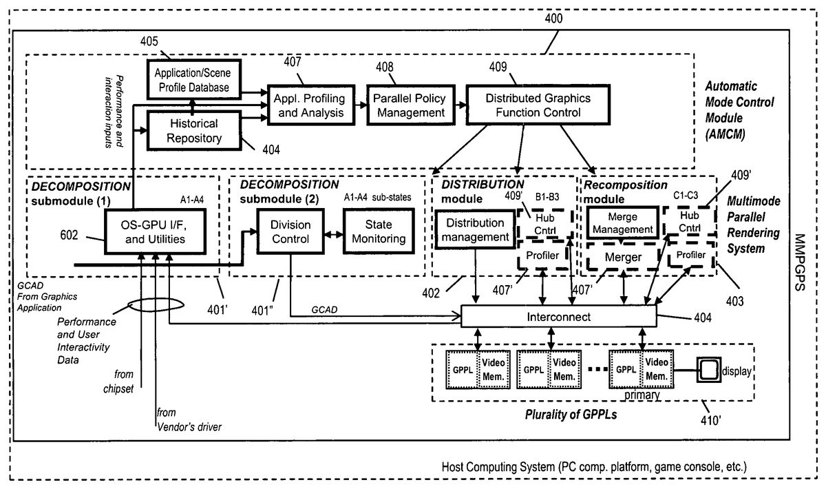
FIG. 4Ashows the MMPGRS of the present invention employing automatic 3D scene profiling and multiple GPPL control, and supporting at least three different parallelization modes (e.g. Image/Frame, Time and Object Division). As shown, the MMPGRS comprises two primary subcomponents, namely:
(1) Multi-Mode Parallel Graphics Rendering Subsystem420including (i) a Decomposition Module401, Distribution Module402and Recomposition Module403for supporting three stages of parallelization namely decomposition, distribution, and recomposition, and (ii) an Array or Cluster of Graphic Processing Pipelines (GPPLs) for supporting and driving Graphics Rendering and Image Display Processes; and
(2) a Automatic Mode Control Module (AMCM)400, described in FIGS.4C through5C4and6A, for dynamically profiling Graphics-based Applications running on the host computing system, and controlling the various modes of parallelism supported by the MMPGRS of the present invention.
In general, the GPPLs can be realized in various ways, including (i) Graphic Processing Units (GPUs)407as shown in FIGS.4B13and4B2, and/or (ii) Computational Processing Units (CPUs), or CPU-cores, as shown in FIGS.4B3and4B4.
As shown inFIGS. 4A and 4D, the Graphics Commands and Data (CGAD) to the MMPGRS will typically be produced and provided from the Graphics-based Application being executed by one or more CPUs and associated memory on the host computing system. In contrast, the Interaction Data will be supplied from the user or users interaction with the host computing system.
In general, the host computing system may be a PC-level computer, application server, laptop, game console system, portable computing system, or the like supporting the real-time generation and display of 3D graphics), and that the MMPGRS may be embodied within any such system in accordance with the principles of the present invention.
The Graphics Processing Pipelines (GPPLs) Employed Within the MMPGRS of the Present Invention
In general, each GPPL employed within the MMPGRS of the present invention can be realized in a variety of different ways. However, in general, each graphics processing pipeline (GPPL) will typically include some basic structures including for example, video memory and a computational unit such as a GPU, or CPU having multi-cores typically implementing SIMD elements. When using GPUs, the graphic processing pipelines (GPPLS) are often considered “hard” graphical processing pipelines. When using CPUs, the graphic processing pipelines are often considered “soft” graphical processing pipelines. In either case, each graphic processing pipeline (GPPL) provides sufficient computational and memory/buffering resources to carry out the execution of graphics commands and the processing of graphics data, as specified by the graphical rendering processed required by the graphics-based Application running on the host computing system, at any particular instant in time.
In FIGS.4B1and4B2, two illustrative embodiments for the GPU-based graphics processing pipeline approach are shown. In FIG.4B3, one illustrative embodiment is shown for the CPU-based graphics processing pipeline approach.
As shown in FIG.4B1, each GPU-based graphics processing pipeline (GPPL) deployed in the MMPGRS of a first illustrative embodiment comprises: (i) video memory (e.g. a stencil memory buffer, a depth memory buffer, and a color memory buffer); and (ii) a classic shader-based GPU which includes: a geometry subsystem; a set up engine; and a pixel subsystem. As shown, the geometry subsystem further comprises a vertex shader which implements a graphics processing function that perform is 3D geometrical transformations and lighting calculations on the objects' vertex data. The Setup engine assembles primitives (lines, points, triangles) from vertices, assigns parameters to primitives, divides the primitives into tiles, and distributes these tiles to the pixel pipelines of the Pixel subsystem. The Pixel subsystem further comprises: a pixel shader for receiving input from the Setup engine and the video memory and performing shading and texturing of pixels; and a plurality of raster operators which receive output from the pixel shader and produce blending, z-buffering and antialiasing of pixels, storing them into Frame Buffer buffer. This graphics pipeline architecture can be found used in conventional graphics devices such as nVidia's GeForce 7700.
As shown in FIG.4B2, each GPU-based graphics processing pipeline (GPPL) deployed in the MMPGRS of a second illustrative embodiment comprises: (i) video memory (e.g. a stencil memory buffer, a depth memory buffer, and a color memory buffer); and (ii) a shader-based GPU which includes: a geometry subsystem; a rasterizer; and a pixel subsystem. As shown, the geometry subsystem further comprises: an input assembler for gathering vertex data from the CPU and converting its format, and generating various index IDs that are helpful for performing various repeated operations on vertices, primitives, and scene objects; a vertex shader for performing 3D geometrical transformations and lighting calculations on the objects' vertex data; and a geometry shader permitting a range of effects and features, such as process entire primitives as inputs and generate entire primitives as output, rather than processing just one vertex at a time, as with a vertex shader, while reducing dependence on the CPU for geometry processing. The stream output permits data generated from geometry shaders to be forwarded back to the top of the pipeline to be processed again. The rasterizer assembles primitives (lines, points, triangles) from vertices, assigns parameters to primitives, and converts them into pixels for output to the Pixel subsystem. The pixel subsystem further comprises: a pixel shader for receiving input from the Setup engine and the video memory and performing shading and texturing of pixels; and a plurality of raster operators which receive output from the pixel shader and produce blending, z-buffering and anti-aliasing of pixels, storing them out into Frame Buffer (FB). This graphics pipeline architecture can be found used in conventional graphics devices such as nVidia's GeForce 8800 GTX.
As shown in FIG.4B3, each CPU-based graphics processing pipeline (GPPL) deployed in the MMPGRS of a third illustrative embodiment comprises: (i) a video memory structure supporting a frame buffer (including stencil, depth and color buffers); (ii) a memory controller; (iii) a graphics processing pipeline realized by one cell of a multi-core CPU chip, consisting of 16 in-order SIMD processors; (iv) L2 cache memory; and (v) a GPU-specific extension, namely, a texture sampler, for loading texture maps from memory, filtering them for level-of-detail, and feeding the same to the pixel processing portion of the graphic processing pipeline (GPPL). This graphics pipeline architecture can be found used in such conventional devices as Larrabee multi-core processor by Intel.
Notably, as shown inFIG. 4A, while the array of GPPLs407comprises N pairs of GPU or CPU and Video Memory pipelines, only one GPPL in the array, termed “primary GPPL,” is responsible for driving the display unit which may be realized as a LCD panel, an LCD or DLP Image/Video “Multi-Media” Projector, or the like. All other GPPLs in the array are deemed “secondary GPPLs.”
The Multi-Mode Parallel Graphics Rendering Subsystem
In the Multi-Mode Parallel Graphics Rendering Subsystem420, each stage (or Module) is induced or set up into a sub-state by a set of parameters managed within the MMPGRS, namely: parameter A for Module401; parameter B for Module402; and parameter C for Module403. The state of parallelism of the overall MMPGRS is established by the combination of sub-state parameters A, B and C, as listed in the Mode/State Definition Table ofFIG. 4C, which will be elaborated hereinafter.
The unique flexibility of the Multi-Mode Parallel Graphics Rendering Subsystem420stems from its ability to quickly change its sub-states, resulting in transition of the overall graphic system (i.e. MMPGS) to another parallel state of operation, namely: the Object Division State, the Image Division State or the Time Division State, as well as to other potential parallelization schemes that may be developed and readily programmed into the MMPGRS platform of the present invention.
Implementing Parallelization Modes Through a Net Combination of Sub-States (A:B:C) Among the Decomposition, Distribution and Recomposition Modules
As indicated in the State Table ofFIG. 4C, the net combination of all Sub-States (A:B:C) among the Decomposition Module401, Distribution Module402and Recomposition Module403, respectively, implements the various parallelization schemes (i.e. parallelization modes) supported on the MMPGRS of the present invention, which will now be described hereinbelow. Thus, the Decomposition Module401, Distribution Module402and Recomposition Module403cooperate to carry out all functions required by the different parallelization schemes supported on the MMPGRS platform of the present invention. It is appropriate at this juncture to described how the primary modes of parallelism (i.e. Image, Time and Object Division) are implemented on the MMPGS using combinations of sub-state parameters (A:B:C).
The Image Division State of Parallel Operation:
In the Image Division State of Operation, the Decomposition Module401is set to the Image Decomposition Sub-State or Sub-mode (A=2), multiplicating the same command and data stream to all GPUs, and defining unique screen portion for each one, according to the specific Image Division Mode in use (e.g. split screen, or tiled screen). The Distribution Module is set in Broadcast Sub-mode B=2, to physically broadcast the stream to all GPUs. Finally, the Recomposition Module No. 1 set to Screen-based Sub-mode C=2, and collects all the partial images into final frame buffer, performing the screen based composition.
The Time Division State of Parallel Operation:
In the Time Division State of Operation, each GPU renders the next successive frame. The Decomposition Module is set to the Alternate Sub-mode, A=3, alternating the command and data stream among GPUs on frame basis. The Distribution Module is set to the Single Sub-mode, B=3, physically moving the stream to the designated GPU. Finally, the Recomposition Module is set to None, C=3, as no merge is needed and the frame buffer is just moved from the designated GPU to the screen for display.
The Object Division State of Parallel Operation:
In the Object Division State of operation, the Decomposition Module is set to the Object Decomposition Sub-mode, A=1, decomposing the command and data stream, and targeting partial streams to different GPUs. The Distribution Module is set to the Divide Sub-mode, B=1, physically delivering the partial commands and data to GPUs. Finally the Recomposition Module is set to Test-Based Sub-mode, C=1, compositing the frame buffer color components of GPUs, based on depth and/or stencil tests.
The Single GPPL State of Operation:
While the Single GPPL State of Operation is a non-parallel state of operation, it is allowed and supported in the system of the present invention as this state of operation is beneficial in some exceptional cases. In the Single GPPL State, the Decomposition, Distribution, and Recomposition Modules are set on Single (A=4), Single (B=3) and None (C=3), respectively. Only one GPPL, among all pipelines supported by the MMPGRS, is used in the single GPPL state of operation.
Description of the Decomposition Module of the MMPGRS of the Present Invention
The primary function of the Decomposition Module401is to divide (i.e. split up) the stream of graphic commands and data (GCAD) according to the required parallelization mode, operative at any instant in time. In general, the typical graphic processing s pipeline is fed by stream of graphic commands and data from the application and graphics library (OpenGL or Direct 3D). This stream, which is sequential in nature, has to be properly handled and eventually partitioned, according to parallelization mode (i.e. method) used. Under the AMCM400, the Decomposition Module can be set to different decomposing sub-states (A=1 through A=4), according toFIG. 4C, namely: Object Decomposition Sub-state A=1 during the Object Division State; Image Decomposition Sub-state A=2 during the Image Division State; Alternate Decomposition Sub-state A=3 during the Time Division State; and the Single Sub-state A=4 during the Single GPPL (Non-Parallel) State. Each one of these parallelization states (i.e. Object, Image, Time and Single/Non-Parallel States) will be described in great technical detail below.
As shown inFIG. 4A, the Decomposition Module401is preferably implemented using two submodules, namely: (i) a Decomposition Submodule No. 1 including an OS-GPU Interface and Utilities Module; and (ii) a Decomposition Submodule No. 2, including a Division Control Module and a State Monitoring Module. The subcomponents of these submodules will be described in detail below.
The OS-GPU Interface and Utilities Module
The OS-GPU Interface and Utilities Module performs all the functions associated with interaction with the Operating System (OS), Graphics Library (e.g. OpenGL or DirectX), and interfacing with GPUs or CPU-cores, as the case may be. The OS-GPU Interface and Utilities Module is responsible for interception of the graphic commands from the standard graphic library, forwarding and creating graphic commands to the Vendor's GPU Driver, controlling registry, installations, OS services and utilities. Another task performed by this module is reading Performance Data from different sources (e.g. GPUs, vendor's driver, and chipset) and forwarding the Performance Data to the Automatic Mode Control Module (AMCM). Also, the OS-GPU Interface and Utilities Module includes software drivers that drive subcomponents within the Decomposition, Distribution and/or Recomposition Modules that are implemented in system architectures (e.g. Hub, Chipset, etc identified in FIG.4A1-2and shown in FIGS.7B1through7B11) in which both the Decomposition and Distribution Modules are not implemented as software packages within the Host Memory Space (HMS) of the host computing system in which the MMPGRS is embodied.
The Division Control Module
In the Division Control Module, all graphics commands and data are processed for decomposition and marked for division. However, these commands and data are sent in a single stream into the Distribution Module for physical distribution. The Division Control Module controls the division parameters and data to be processed by each GPU, according to parallelization scheme instantiated at any instant of system operation (e.g. division of data among GPUs in the Object Division Mode, or the partition of the image screen among GPUs in the Image Division Mode).
In the Image Division Mode, the Division Control Module assigns for duplication all the geometric data and common rendering commands to all GPUs. However specific rendering commands to define clipping windows corresponding to image portions at each GPU, are assigned separately to each GPU.
In the Object Division Mode, polygon division control involves sending each polygon (in the scene) randomly to a different GPU within the MMPGRS. This is an easy algorithm to implement, and it turns out to be quite efficient. There are different variations of this basic algorithm, as described below.
Polygon Division Control by Distribution of Vertex Arrays
According to this method, instead of randomly dividing the polygons, the vertex-arrays can be maintained in their entirety and sent to different GPUs, as the input might be in the form of vertex arrays, and dividing it may be too expensive.
Polygon Division Control by Dynamic Load Balancing
According to this method, GPU loads are detected at real time and the next polygon is sent to the least loaded GPU. Dynamic load balancing is achieved by building complex objects (out of polygons). GPU loads are detected at real time and the next object is sent to the least loaded GPU.
Handling State Validity Across the MMPGRS by State Monitoring
The graphic libraries (e.g. OpenGL and DirectX) are state machines. Parallelization must preserve a cohesive state across all of the GPU pipelines in the MMPGRS. According to this method, this is achieved by continuously analyzing all incoming graphics commands, while the state commands and some of the data is duplicated to all graphics pipelines in order to preserve the valid state across all of the graphic pipelines in the MMPGRS. This function is exercised mainly in Object Division Mode, as disclosed in detail in Applicant's previous International Patent PCT/IL04/001069, now published as WIPO International Publication No. WO 2005/050557, incorporated herein by reference in its entirety.
The Description of the Distribution Module of the Present Invention
The primary function of the Distribution Module402is to physically distribute the streams of graphics data and commands to the cluster of GPUs supported on the MMPGRS platform. Under the AMCM400, the Distribution Module can be set to different distribution sub-states (B=1 through B=3), according toFIG. 4C, namely: the Divide Sub-state B1during the Object Division State; the B=2 Sub-state (i.e. the Broadcast Sub-state) during the Image Division State; and the B3Sub-state (i.e. Single GPU Sub-state) during the Time Division and Single GPU (i.e. Non-Parallel system) States. As shown inFIG. 4A, an additional source of Performance Data (i.e. beyond the GPUs, vendor's driver, and chipset) includes the internal Profiler employed in the Distribution Module in Hub-based embodiments of the present invention.
As shown inFIG. 4A, the Distribution Module is implemented by the following components: (i) the Distribution Management Module, which addresses the streams of graphics commands and data to the different GPPLs via chipset outputs, according to needs of the parallelization schemes instantiated by the MMPGRS; (iii) Profiler module used in graphics hub type system architectures, as illustrated in FIGS.7B1through7B12, so as to provide an additional source of Performance Data (i.e. beyond the GPUs, vendor's driver, and chipset); and (iv) a Hub Control module, operating under control of the Distributed Graphics Function Control Module409within the AMCM400, in graphics hub type system architectures, as illustrated in FIGS.7B1through7B12, for configuring the Interconnect Network404according to the various parallelization modes and to coordinate the overall functioning of hardware components within the Recomposition Module across the graphics hub device (GHD) of the present invention.
As shown inFIG. 4A, the Distribution Module402″ comprises three functional units: the Distribution Management, the Profiler, and the Hub Control modules. The Distribution Management activates the Interconnect network404to transfer command and data stream to the GPPLs. The Interconnect network serves to (i) transfer command and data stream from the CPU to GPPLs, (ii) transfer raster data from GPPLs to the Recomposition Module, (iii) transfer raster data among GPPUs for an alternative GPPL-based Recomposition, and (iv) conduct other communication tasks, such as profiling data, control, etc. among the various system components.
An exemplary embodiment of Interconnect for a cluster of 4 GPPLs is a configurable switch with 5 way PCI express ×16 lanes, having one upstream path between Hub and CPU, and 4 downstream paths between Hub and four GPUs. It receives upstream of commands and data from the CPU, and transfers them downstream to GPPLs, under the control of Distribution Management unit (of Distribution module), following the data division scheme generated by the Division Control block of Decomposition sub-module (2), according to ongoing parallel division mode. The switch can be set into one of the following possible transfer sub-states: Divide, Broadcast, and Single. The Divide sub-state is set when the MMGPRS is operating in its Object Division Mode. The Broadcast sub-state is set when the MMGPRS is operating in its Image Division Mode. The Single sub-state is set when the MMGPRS is operating in its Time Division Mode, or in Single mode.
Within the Distribution Module, the Profiler Unit407′ has several functions in system architectures employing graphics hub device (GHD)s as illustrated in FIG.7B1through7B12, namely: (i) to deliver to Division Control its own generated profiling data; (ii) to forward the profiling data from GPUs to Division Control, due the fact that the GPUs are not directly connected to the host computing system in graphics hub based system architectures, whereas they are in system architectures illustrated in FIGS.7A2through7A7-3; and (iii) to forward the Hub pre-GPU profiling data to the Division Control block within the Decomposition Module. Being close to the raw data passing by the GPUs, the Profiler403monitors the stream of geometric data and commands, for graphics hub profiling purposes. Such monitoring operations involve polygon, command, and texture count and quantifying data structures and their volumes for load balance purposes. The collected data is mainly related to the performance of the geometry subsystem employed in each GPU.
Within the Distribution Module of system architectures employing the graphics hub device (GHD) of the present invention, illustrated in FIGS.7B1through7B12, the Hub Controller Module409′, operates under control of the Distributed Graphics Function Control Module409within the Automatic Mode Control Module400. The primary function performed by this Hub Controller Module409′ is to configure the Interconnect Network404according to the various parallelization modes and to coordinate the overall functioning of hardware components across the Distribution Module of the graphics hub device (GHD) of the present invention.
The Description of the Recomposition Module of the Present Invention
The primary function of the Recomposition Module403is to merge together, the partial results of multiple graphics pipelines, according to parallelization mode that is operative at any instant in time. The resulting or final Frame Buffer (FB) is sent to the display device (via primary GPU, or directly Under the AMCM400, the Recomposition Module can be set to three different decomposing sub-states (C=1 through C=3), according toFIG. 4C, namely: The Test Based Sub-state C=1; the Screen Based Sub-state C=2; and the None State C=3. The Test based sub-state carries out re-composition based on a test performed on partial frame buffer pixels. Typically, these tests include the depth test, the stencil test, or combination thereof. The Screen based sub-state combines together parts of the final frame buffers, in a puzzle like fashion, creating a single image. The None sub-state, or submode, makes no merges, just moves one of the pipeline frame buffers to the display, as required in time division parallelism or in single GPU (Non-Parallel) mode of operation.
The Test-Based Compositing suits compositing during the Object Division Mode. According to this method, sets of Z-buffer, stencil-buffer and color-buffer are read back from the GPU FBs to host's memory for compositing. The pixels of color-buffers from different GPUs are merged into single color-buffer, based on per pixel comparison of depth and/or stencil values (e.g. at given x-y position only the pixel associated with the lowest z value is let out to the output color-buffer). This is a software technique to perform hidden surface elimination among multiple frame buffers required for the Object Division Mode. Frame buffers are merged based on depth and stencil tests. Stencil tests, with or without combination with depth test, are used in different multi-pass algorithms. The final color-buffer is down-loaded to the primary GPU for display.
Screen-Based Compositing Suits Compositing During the Image Division Mode
The Screen-Based compositing involves a puzzle-like merging of image portions from all GPUs into a single image at the primary GPU, which is then sent out to the display. This method is a much simpler procedure than the Test-Based Compositing Method, as no tests are needed. While the primary GPU is sending its color-buffer segment to display, the Merger Module reads back other GPUs color-buffer segments to host's memory, for downloading them into primary GPU's FB for display.
The None Sub-state is a non-compositing option which involves moving the incoming Frame Buffer to the display. This option is used when no compositing is required. In the Time Division Mode, a single color-buffer is read back from a GPU to host's memory and downloaded to primary GPU for display. In the Non-Parallel Mode (e.g. employing a single GPPL), usually the primary GPPL is employed for rendering, so that no host memory transit is needed.
In the illustrative embodiments, the Recomposition Module is realized by several modules: (i) the Merge Management Module which handles the reading of frame buffers and the compositing during the Test-Based, Screen-Based And None Sub-States; (ii) the Merger Module which is an algorithmic module that performs the different compositing algorithms, namely, Test Based Compositing during the Test-Based Sub-state, and Screen Based Compositing during the Screen-Based Sub-state; (iii) Profiler module used in graphics hub type system architectures, as illustrated in FIGS.7B1through7B12, so as to provide an additional source of Performance Data (i.e. beyond the GPUs, vendor's driver, and chipset); and (iv) a Hub Control module, operating under control of the Distributed Graphics Function Control Module409within the AMCM400, in graphics hub type system architectures, as illustrated in FIGS.7B1through7B12, for configuring the Interconnect Network404according to the various parallelization modes and to coordinate the overall functioning of hardware components within the Recomposition Module across the graphics hub device (GHD) of the present invention.
In the case where the Interconnect needs to interconnect a cluster of 4 GPPLs, a configurable switch can be used having 5 way PCI express ×16 lanes, with one upstream path between the Hub and CPU, and 4 downstream paths between Hub and four GPUs. Under the local control of the Merge Management and the Hub Controller in the Recomposition Module, the Interconnect (e.g. switch) also performs the following functions: (i) transferring read-back FB raster data from GPPLs to the Merger block of Recomposition Module and returning composited image to primary GPPL, all under orchestration of the Merge Management block; (ii) transferring the read-back FB raster data among GPPLs for GPPL-based recomposition, so that the finally recomposited pixel data in final image is composited in the primary GPPL; (iii) transferring additional data, e.g. profiler data, to Decomposition module; and (iv) transferring control commands across the MMPGRS system.
Within the Recomposition Module, the Profiler unit403has several functions in system architectures employing graphics hub device (GHD)s as illustrated in FIG.7B1through7B12, namely: (i) to deliver to Division Control its own generated profiling data; (ii) to forward the profiling data from GPUs to Division Control, due the fact that the GPUs are not directly connected to the host computing system in graphics hub based system architectures, whereas they are in system architectures illustrated in FIGS.7A2through7A7-3; and (iii) to forward the Hub post-GPU profiling data to the Division Control block within the Decomposition Module. Being close to the raw data passing by the GPUs, the Profiler403monitors the stream of geometric data and commands, for graphics hub profiling purposes. Such monitoring operations involve polygon, command, and texture count and quantifying data structures and their volumes for load balance purposes. The collected data is mainly related to the performance of the geometry subsystem employed in each GPU.
Another function performed by the Profiler403within the Recomposition Module is to profile the merge process and monitor the task completion of each GPU for load balancing purposes. In graphics hub device (GHD) class of system architecture illustrated in FIGS.7B1through7B12, both Profilers407′ and403′, in the Distribution and Recomposition Modules, unify their collected Performance Data and deliver the unified performance data, as feedback, to the Automatic Mode Control Module (AMCM) via the Decomposition Module, as shown inFIG. 4A. Notably, the communication linkage between the two Profiling blocks is achieved using the Interconnect network404. In some illustrative embodiments, the two “pre-GPU” and “post-GPU” units of the graphics hub device (GHD), formed by the components within the Distribution and Recomposition Modules of system architectures illustrated in FIGS.7B1through7B12, may reside on the same silicon chip, having many internal interconnections, whereas in other illustrative embodiments, these subcomponents may be realized on different pieces of silicon or functionally like semiconductor material, used to fabricate the graphics hub device (GHD)s of the present invention within diverse embodiments of the MMPGRS of the present invention.
Within the Recomposition Module of system architectures employing the graphics hub device (GHD) of the present invention, illustrated in FIGS.7B1through7B12, the Hub Controller Module409′, operates under control of the Distributed Graphics Function Control Module409within the AMCM400. The primary function performed by this Hub Controller Module409′ is to configure the Interconnect Network404according to the various parallelization modes and to coordinate the overall functioning of hardware components across the Recomposition Module of the graphics hub device (GHD) of the present invention.
Notably, in some illustrative embodiments of the present invention, the Hub Controllers409′, in the Distribution and Recomposition Modules in system architectures embraced by the graphics hub device (GHD) of the present invention, can be realized as a single device or unit, on the same piece of silicon or like semiconductor material. In other embodiments, the Hub Controllers409′ can be realized as discrete units, on the same piece of silicon or like semiconductor material, or on separate pieces of silicon material (e.g. on different chips sets).
Description of the Automatic Mode Control Module (AMCM)400Within the MMPGRS of the Present Invention
During the run-time of any graphics-based application on the host computing system, the MMPGRS renders and displays the graphics environment being generated by the application, which typically will include many dynamically changing scenes, where the plot unfolds, and each scene typically involves a sequence of many image frames. Such scenes could involve virtually anything, including a forest with many leaves moving in the wind, a lake with many reflections, or a closed space in a castle with many light sources. Such scenes require parallel rendering, and the role of the MMPGS is to automatically determine which mode of parallel operation will result in optimal performance on the host computing system.
As shown inFIG. 4A, the Automatic Mode Control Module (AMCM)400comprises three algorithmic modules, namely: an Application Profiling and Analysis Module407; a Parallel Policy Management Module408; and a Distributed Graphics Function Control.
In the preferred embodiment shown inFIG. 4B, the AMCM also comprises two data stores: a Historical Repository404; and a Application/Scene Profile Database405. The primary function of the AMCM is to control the state of Multi-mode Parallel Rendering Subsystem410by virtue of its flexible multi-state behavior and fast interstate transition capabilities.
As shown inFIG. 4C, the AMCM400comprises a User Interaction Detection (UID) Subsystem438which includes a Detection and Counting Module433in combination with a UID Transition Decision Module436. These subsystems and modules will be described in greater detail hereinbelow.
Overview on the Automatic Mode Control Module (AMCM) in the MMPGRS of the Present Invention
When implementing the Automatic Mode Control Module or Mechanism (AMCM) in the MMPGRS of the present invention, there are several classes of techniques which can be usefully applied, to determine when and how to switch into, out of, and transition between modes of parallel operation on the MMPGRS platform, during the run-time of a particular graphics-based application, and optimize system performance, namely: Mode Control Techniques Based On Scene/Application Profiling; and Mode Control Techniques Based On System-User Interaction Detection. It is appropriate at this juncture to provide an overview on the various techniques that the AMCM can use to best determine how to automatically control the mode of parallel operation on the MMPGRS Platform, and optimize system performance.
Description of Mode Control Techniques Employed Within the AMCM Based on Scene/Application Profiling
(1) Real-Time Profiling of Scenes (on a Frame-by-Frame Basis):
This method involves collecting and analysis of Performance Data, during application run-time, in order to construct scene profiles for image frames associated with particular scenes in a particular graphics-based application, and maintaining these scene profiles in the Scene/Application Profile Database within the AMCM. This way, during run-time, the AMCM can access and use these scene profiles so as to best determine how to dynamically control the modes of parallel operation of the MMPGRS to optimize system performance. As will be described in greater detail hereinafter, this technique can be practiced using the Application Profiling and Analysis Module407and Parallel Policy Management Module408illustrated inFIGS. 4A,4D,5C1,5C2,5C3, and5C4, in the context of highly diverse MMPGRS system architectures, as well as within multi-user application environments supported over distributed network environments, as shown inFIGS. 12A and 12B.
(2) Real-Time Detection of Scene Profile Indices Directly Programmed Within Pre-Profiled Scenes of Particular Applications:
This technique involves analyzing, prior to run-time, the scenes of a particular application, and then indexing the scene with Scene Profile Indices and storing corresponding Mode Control Parameters (MCPs) (e.g. Switch to Object Division Mode) within the local Scene/Application Profile Database within the AMCM, or other data storage device that is accessible in real-time by the AMCM during application run-time. Then during run-time, the AMCM automatically detects the scene, and consults the Scene Profile Indices for the corresponding MCPs from the Scene/Application Profile Database so as to best determine how to dynamically control the modes of parallel operation of the MMPGRS to optimize system performance.
(3) Real-Time Detection of Mode Control Command (MCCs) Directly Programmed Within Pre-Profiled Scenes of Particular Applications:
This technique involves, prior to run-time (e.g. during game application development), analyzing the scenes of a particular application, and the directly programming Mode Control Commands (MMCs) (e.g. Switch to Object Division Mode) within the individual image frames of each scene, following standards to be established and followed by developers in the computer graphics industry. Then during run-time, the MCM automatically detects these MCCs along the graphics command and data stream, and use these commands so as to best determine how to dynamically control the modes of parallel operation of the MMPGRS to optimize system performance.
Description of Mode Control Techniques Employed Within the AMCM Based on System-User Interaction Detection
This approach, which can be used in conjunction with any of the above Scene/Application Profiling Techniques, involves automatically detecting the users interaction with the host computing system (e.g. mouse device movement, keyboard depressions, etc) and providing this Interaction Data to the AMCM so that it can best determine how to dynamically control the modes of parallel operation of the MMPGRS to optimize system performance, given the user's interaction with the host computing system, or application running thereon, at any instance in time. As will be described in greater detail hereinafter, this technique can be practiced using the UID Subsystem438illustrated inFIGS. 5A,5B and5C2.
The Application Profiling and Analysis Module
As shown inFIG. 4D, the Application Profiling and Analysis Module407monitors and analyzes Performance and Interactive data streams continuously acquired by profiling the Application while its running. InFIG. 5D, the Performance Data inputs provided to the Application Profiling and Analysis Module include: texture count; screen resolution; polygon count; utilization of geometry engine, pixel engine, video memory and GPPL; the total pixels rendered, the total geometric data rendered; the workload of each GPPL; the volumes of transferred data. The System-User Interactive (Device) Data inputs provided to the Application Profiling and Analysis Module include: mouse movement; head movement; voice commands; eye movement; feet movement; keyboard; LAN, WAN or Internet (WWW) originated application (e.g. game) updates.
The Tasks performed by the Application Profiling and Analysis Module include: Recognition of the Application; Processing of Trial and Error Results; Utilization of Application Profile from Application/Scene Profile Database; Data Aggregation in the Historical Depository; Analysis of input performance data (frame-based); Analysis based on integration of frame-based “atomic” performance data, aggregated data at Historical Depository, and Application/Scene Profile Database data; Detection of rendering algorithms used by Application; Detection of use of FB in next successive frame; Recognition of preventative conditions (to parallel modes); Evaluation of pixel layer depth; Frame/second count; Detection of critical events (e.g. frames/sec/drop); Detection of bottlenecks in graphics pipeline; Measure of load balance among GPUs; Update Application/Scene Profile Database from the Historical Depository; and Recommendation on optimal parallel scheme.
The Application Profiling and Analysis Module performs its analysis based on the following:
(1) The Performance Data collected from several sources, such as vendor's driver, GPUs, chipset, and optionally—from the graphics Hub embodiments of the present invention, described in greater detail hereinafter;
(2) Historical repository404which continuously stores up the acquired data (i.e. this data having historical depth, and being used for constructing behavioral profile of ongoing application); and
(3) Knowledge based Application/Scene Profile Database405which is an application profile library of prior known graphics applications (and further enriched by newly created profiles based on data from the Historical Depository).
In the MMGPRS of the illustrative embodiment, the choice of parallel rendering mode at any instant in time involves profiling and analyzing the system's performance by way of processing both Performance Data Inputs and Interactive Device Inputs, which are typically generated from a several different sources within MMPGRS, namely: the GPUs, the vendor's driver, the chipset, and the graphic Hub (optional).
Performance Data needed for estimating system performance and locating casual bottlenecks, includes:(I) Texture Count;(Ii) Screen Resolution;(Iii) Polygon Volume;(iv) at each GPPL, utilization of(a) the Geometry Engine(b) the Pixel engine, and(c) Video memory;(v) Utilization of the CPU;(vi) total pixels rendered;(vii) total geometric data rendered;(viii) workload of each GPU; and(ix) volumes of transferred data.
As shown inFIG. 4D, this Performance Data is fed as input into the Application Profiling and Analysis Module for real-time processing and analysis Application Profiling and Analysis Module. In the illustrative embodiment, the Application Profiling and Analysis Module performs the following tasks:(1) Recognition of Application (e.g. video game, simulation, etc.);(2) Processing of trial & error results produced by the processes described in FIGS.5C3and5C4;(3) Utilization of the Application Profile from data in the Application/Scene Profile Database;(4) Aggregation of Data in the Historical Repository;(5) Analysis of Performance Data Inputs;(6) Analysis based on the integration of(a) Frame-based “atomic” Performance Data,(b) Aggregated data within the Historical Repository, and(c) Data stored in the Application/Scene Profile Database;(7) Detection of rendering algorithms used by Application(8) Detection of use of the FB in next successive frame as a preventive condition for Time Division Mode;(9) Recognition of preventive conditions for other parallel modes;(10) Evaluation of pixel layer depth at the pixel subsystem of GPU;(11) Frame/sec count;(12) Detection of critical events (e.g. frame/sec drop);(13) Detection of bottlenecks in graphics pipeline;(14) Measure and balance of load among the GPUs;(15) Update Application/Scene Profile Database from data in the Historical Depository; and(16) Selection of the optimal parallel graphics rendering mode of operation for the MMPGRS.
The Parallel Policy Management Module
Parallel Policy Management Module408makes the final decision regarding the preferred mode of parallel graphics rendering used at any instant in time within the MMPGRS, and this decision is based on the profiling and analysis results generated by the Application Profiling and Analysis Module. The decision is made on the basis of some number N of graphics frames. As shown above, the layer depth factor, differentiating between the effectiveness of the Object Division vs. Image Division Mode, can be evaluated by analyzing the relationship of geometric data vs. fragment data at a scene, or alternatively can be found heuristically. Illustrative control policies have been described above and in FIGS.5C1through5C3.
The Distributed Graphic Function Control Module
Distributed Graphic Function Control Module409carries out all the functions associated with the different parallelization modes, according to the decision made by the Parallel Policy Management Module. The Distributed Graphic Function Control Module409drives directly the configuration sub-states of the Decomposition, Distribution and Recomposition Modules, according to the parallelization mode. Moreover, Application Profiling and Analysis includes drivers needed for hardware components such as graphic Hub, described hereinafter in the present Patent Specification.
State Transitions Within the MMPGRS of the Illustrative Embodiment of the Present Invention
As shown in the state transition diagram ofFIG. 6A, the MMPGRS of the illustrative embodiment has six (6) system states. Three of these system states are parallel graphics rendering states, namely: the Image Division State, which is attained when the MMPGRS is operating in its Image Division Mode; the Object Division State, which is attained when the MMPGRS is operating in its Object Division Mode; and the Time Division State, which is attained when the MMPGRS is operating in its Time Division Mode. The system also includes a Non-Parallel Graphics Rendering State, which is attained only when a single GPPL is operational during the graphics rendering process. There is also an Application Identification State, and a Trial & Error Cycle State. As illustrated inFIG. 4CandFIG. 6A, each parallelization state is characterized by sub-state parameters A, B, C. As shown in the state transition diagram ofFIG. 6A, the Non-Parallel (i.e. Single GPPL) State is reachable from any other state of system operation.
In accordance with the principles of the present invention, profiles of all previously analyzed and known graphics-based Applications are stored in the Application/Scene Profile Database405of the MMPGRS. Whenever the graphics-based application starts, the system enters Application Identification State, and the AMCM attempts to automatically identify whether this application is previously known to the system. In the case of a previously known application, the optimal starting state is recommended by the Database, and the system transitions to that system state. Further on, during the course of the application, the AMCM is assisted by the Application/Scene Profile Database to optimize the inter-state tracking process within the MMPGRS. In the case of an application previously unknown to the MMPGRS, the Trial & Error Cycle State is entered, and attempts to run all three parallelization schemes (i.e. Modes) are made for a limited number of cycles.
During the course of the Application, the decision by the system as to which mode of graphics rendering parallelization to employ (at any instant in time) is supported either by continuous profiling and analysis, and/or by trial and error. The Trial and Error Process is based on comparing the results of a single, or very few cycles spent by the system at each parallelization state.
During the course of continuous profiling and analysis by the Application Profiling and Analysis Module407, the following parameters are considered and analyzed by the AMCM with respect to each state/mode transition decision:Pixel processing loadScreen resolutionDepth complexity of the scenePolygon countVideo-memory usageFrame/second rateChange of frames/second rateTolerance of latencyUse of the same FB in successive frame(10) User-System Interaction during the running of the Application.
User-Interactivity Driven Mode Selection Within the MMPGRS of the Present Invention
Purely in terms of “frames/second” rate, the Time Division Mode is the fastest among the parallel graphics rendering modes of the MMGRS, and this is by virtue of the fact that the Time Division Mode works favorably to reduce geometry and fragment bottlenecks by allowing more time. However, the Time Division Mode (i.e. method) of parallelization does not solve video memory bottlenecks. Also, the Time Division Mode suffers from other problems, namely: (i) CPU bottlenecks; (ii) the unavailability of GPU-generated frame buffers to each other, in cases where the previous frame is required as a start point for the successive frame; and also (iii) from pipeline latency. Automatic transition of the MMGPRS to its Object-Division Mode effectively releases the system from transform and video memory loads. In many applications, these problems provide reasons not for the MMPGS to use or enter into its Time Division Mode. However, for some other applications, the Time Division Mode may be suitable and perform better than other parallelization schemes available on the MMGPRS of the present invention (e.g. Object-Division Mode and Image-Division Mode).
During the Time Division Mode, the pipeline latency problem arises only when user-system interaction occurs. Also, in many interactive gaming applications (e.g. video games), often there are 3D scenes with intervals of user-system interactivity during the Time Division Mode. Thus, in order to achieve the highest performance mode of parallel graphics rendering at runtime, the MMPGRS of the present invention employs a User Interaction Detection (UID) Subsystem438which enables automatic and dynamic detection of the user's interaction with the system. Absent preventive conditions (such as CPU bottlenecks and need for the same FB in successive frames), the UID subsystem438enables timely automated implementation of the Time Division Mode only when no user-system interactivity is detected so that system performance is automatically optimized.
These and other constraints are taken into account during the inter-modal transition process, as illustrated in the State Transition Diagram ofFIG. 6A, and described below:
Transition from Object Division to Image Division follows a combination of one or more of the following conditions:Increase in pixel processing loadIncrease in screen resolutionIncrease in scene depth complexityDecrease in polygon count
Transition from Image Division to Object Division follows a combination of one or more of the following conditions:Increase of polygon countIncrease of video memory footprintDecrease of scene depth complexity
Transition from Object Division to Time Division follows a combination of one or more of the following conditions:Demand for higher frame/second rateHigher latency is toleratedThere is no use of the FB for successive frameNo predefined input activity detected by the UID Subsystem
Transition from Time Division to Object Division follows a combination of one or more of the following conditions:Latency is not tolerableFB is used for successive frameHigh polygon countInput activity detected by the UID Subsystem
Transition from Time Division to Image Division follows a combination of one or more of the following conditions:Latency is not tolerableFB is used for successive frameHigh pixel processing loadInput activity detected by the UID Subsystem
Transition from Image Division to Time Division follows a combination of one or more of the following conditions:Demand for higher frame/second rateLatency is tolerableHigh polygon countNo predefined input activity detected by the UID Subsystem.
In the illustrative embodiment, this capacity of the MMPGRS is realized by the User Interaction Detection (UID) Subsystem438provided within the Application Profiling and Analysis Module407in the Automatic Mode Control Module of the system. As shown inFIG. 5A, the UID subsystem438comprises: a Detection and Counting Module433in combination with a UID Transition Decision Module436.
As shown inFIGS. 5A and 4D, the set of interactive devices which can supply User Interactive Data to the UID subsystem can include, for example, a computer mouse, a keyboard, eye-movement trackers, head-movement trackers, feet-movement trackers, voice command subsystems, Internet, LAN, WAN and/or Internet originated user-interaction or game updates, and any other means of user interaction detection, and the like.
As shown inFIG. 5A, each interactive device input432supported by the computing system employing the MMPGRS feeds User Interaction Data to the Detection and Counting Module433which automatically counts the elapsed passage of time for the required non-interactive interval. When such a time interval is counted or has elapsed (i.e. without detection of user-system interactivity), the Detection and Counting Module433automatically generates a signal indicative of this non-interactivity (434) which is transmitted to the UID Transition Decision Module436. Thereafter, UID Transition Decision Module436issues a state transition command (i.e. signal) to the Parallel Policy Management Module408, thereby causing the MMPGRS to automatically switch from its currently running parallel mode of graphics rendering operation, to its Time Division Mode of operation. During the newly initiated Time Division Mode, whenever system-user interactivity from the interactive device is detected432by the Detection and Counting Module433, an system-user interactivity signal435is transferred to the UID Transition Decision Module436, thereby initiating the system to return from the then currently Time Division Mode, to its original parallel mode of operation (i.e. the Image or Object Division Mode, as the case may be).
As shown inFIG. 5A, an Initialization Signal431is provided to the Detection and Counting Module433when no preventive conditions for Time Division exist. The function of the Initialization Signal431is to (1) define the set of input (interactive) devices supplying interactive inputs, as well as (2) define the minimum elapsed time period with no interactive activity required for transition to the Time Division Mode (termed non-interactive interval). The function of the UID Transition Decision Module436is to receive detected inputs435and no inputs434during the required interval, and, produce and provide as output, a signal to the Parallel Policy Management System, initiating a transition to or from the Time Division Mode of system operation, as shown.
In applications dominated by Image Division or Object Division Modes of operation, with intervals of non-interactivity, the UID Subsystem438within the MMGPRS can automatically initiate a transition into its Time Division Mode upon detection of user-interactivity, without the system experiencing user lag. Then as soon as the user is interacting with the application, the UID Subsystem of the MMGPRS can automatically transition (i.e. switch) the system back into its dominating mode (i.e. the Image Division or Object Division). The benefits of this method of automatic “user-interaction detection (UID)” driven mode control embodied within the MMGRPS of the present invention are numerous, including: best performance; no user-lag; and ease of implementation.
Notably, the automated event detection functions described above can be performed using any of the following techniques: (i) detecting whether or not a mouse movement or keyboard depression has occurred within a particular time interval (i.e. a strong criterion); (ii) detecting whether or not the application (i.e. game) is checking for such events (i.e. a more subtle criterion); or (iii) allowing the application's game engine itself to directly generate a signal indicating that it is entering an interactive mode.
The state transition process between Object-Division/Image-Division Modes and the Time Division Mode initiated by the UID subsystem of the present invention is described in the flow-chart shown inFIG. 5B. As shown therein, at Block A, the UID subsystem is initialized. At Block B, the time counter of the Detection and Counting Module433is initialized. At Block C, the UID subsystem counts for the predefined non-interactive interval, and the result is repeatedly tested at Block D. When the test is positively passed, the parallel mode is switched to the Time-Division at Block E by the Parallel Policy Management Module. At Block F, the UID subsystem determines whether user interactive input (interactivity) has been detected, and when interactive input has been detected, the UID subsystem automatically returns the MMPGRS to its original Image or Object Division Mode of operation, at Block G ofFIG. 5B.
As will be described in greater detail below, the entire process of User-Interactivity-Driven Mode Selection occurs within the MMPGRS of the present invention when N successive frames according control policy are run in either the Object Division or Image Division Mode of operation, as shown during Blocks I and J of FIGS.5C1and5C2.
Operation of the Automatic Mode Control Cycle Within the MMPGRS of the Present Invention
Referring to FIG.5C1, the Profiling and Control Cycle Process within the MMPGRS will now be described in detail, wherein each state transition is based on above listed parameters (i.e. events or conditions) (1) through (6) listed above, and the UID Subsystem is disabled. In this process, Steps A through C test whether the graphics application is listed in the Application/Scene Profile Database of the MMPGRS. If the application is listed in the Application/Scene Profile Database, then the application's profile is taken from the Database at Step E, and a preferred state is set at Step G. During Steps I-J, N successive frames are rendered according to Control Policy, under the control of the AMCM with its UID Subsystem disabled. At Step K, Performance Data is collected, and at Step M, the collected Performance Data is added to the Historical Repository, and then analyzed for next optimal parallel graphics rendering state at Step F. Upon conclusion of application, at Step L, the Application/Scene Profile Database is updated at Step N using Performance Data collected from the Historical Repository.
Referring to FIG.5C2, the Profiling and Control Cycle Process within the MMPGRS will now be described in detail, with the UID Subsystem is enabled. In this process, Steps A through C test whether the graphics application is listed in the Application/Scene Profile Database of the MMPGRS. If the application is listed in the Application/Scene Profile Database, then the application's profile is taken from the Database at Step E, and a preferred state is set at Step G. During Steps I-J, N successive frames are rendered according to Control Policy under the control of the AMCM with its UID Subsystem enabled and playing an active role in Parallel Graphics Rendering State transition within the MMPGRS. At Step K, Performance Data is collected, and at Step M, the collected Performance Data is added to the Historical Repository, and then analyzed for next optimal parallel graphics rendering state at Step F. Upon conclusion of application, at Step L, the Application/Scene Profile Database is updated at Step N using Performance Data collected from the Historical Repository.
Operation of the Periodical Trial & Error Process of the Present Invention Within the MMPGRS of the Present Invention
As depicted in FIG.5C3, the Periodical Trial & Error Process differs from the Profiling and Control Cycle Process/Method described above, based on its empirical approach. According the Periodical Trial & Error Process, the best parallelization scheme for the graphical application at hand is chosen by a series of trials described at Steps A through M in FIG.5C3. After N successive frames of graphic data and commands are processed (i.e. graphically rendered) during Steps N through O, another periodical trial is performed at Steps A through M. In order to omit slow and unnecessary trials, a preventive condition for any of the parallelization schemes can be set and tested during Steps B, E, and H, such as used by the application of the Frame Buffer FB for the next successive frame, which prevents entering the Time Division Mode of the MMPGRS.
In the flowchart of FIG.5C4, a slightly different Periodical Trial & Error Process (also based on an empirical approach) is disclosed, wherein the tests for change of the parallel graphics rendering state (i.e. mode) are done only in response to, or upon the occurrence of a drop in the frame-rate-per-second (FPS), as indicated during Steps O, and B through M.
Conditions for Transition Between Object and Image Division Modes of Operation in the MMPGRS of the Present Invention
In a well-defined case, Object Division Mode supersedes the Image Division Mode in that it reduces more bottlenecks. In contrast to the Image Division Mode that reduces only the fragment/fill bound processing at each GPU, the Object Division Mode relaxes bottleneck across the pipeline: (i) the geometry (i.e. polygons, lines, dots, etc) transform processing is offloaded at each GPU, handling only 1/N of polygons (N—number of participating GPUs); (ii) fill bound processing is reduced since less polygons are feeding the rasterizer; (iii) less geometry memory is needed; and (iv) less texture memory is needed.
Automated transition to the Object Division State of operation effectively releases the MMPGRS of the present invention from transform and video memory loads. However, for fill loads, the Object Division State of operation will be less effective than the Image Division State of operation.
At this juncture it will be helpful to consider under what conditions a transition from the Object Division State to the Image Division State can occur, so that the parallel graphics system of the present invention will perform better “fill loads”, especially in higher resolution.
Notably, the duration of transform and fill phases differ between the Object and Image Division Modes (i.e. States) of operation. For clarity purposes, consider the case of a dual-GPU graphics rendering system. Rendering time in the Image Division Mode is given by:
TObjDiV=Transform+Fill/2 (1)
whereas in Object Division Mode, the fill load does not reduce in the same factor as transform load.
The render time is:
TImgDiv=Transform/2+DepthComplexity*Fill/2 (2)
The fill function Depth Complexity in Object Division Mode depends on depth complexity of the scene. Depth complexity is the number of fragment replacements as a result of depth tests (the number of polygons drawn on every pixel). In the ideal case of no fragment replacement (e.g. all polygons of the scene are located on the same depth level), the second component of the Object Division Mode reduces to:
TImgDiv=Transform/2+Fill/2 (2.1)
However, when depth complexity becomes high, the advantage of the Object Division Mode drops significantly, and in some cases the Image Division Mode may even perform better (e.g. in Applications with small number of polygons and high volume of textures).
The function DepthComplexity denotes the way the fill time is affected by depth complexity:
DepthComplexity=2E(L/2)E(L)(3)
where E(L) is the expected number of fragments drawn at pixel for L total polygon layers.
In ideal case DepthComplexity=1. In this case, E is given by:
E(m)=1+1m(∑i=1m-1E(i))(3.1)
For a uniform layer-depth of L throughout the scene, the following algorithm is used to find conditions for switching from the Object Division Mode to the Image Division Mode:
chose_div_mode(Transform,Fill)={ObjectDivisionTransform+Fill2>Transform2+Fill2×DepthComplexityImageDivisionotherwise(4)
In order to choose between the Image Division and the Object Division Mode, an algorithm is used which detects which transform and fill bound processing is smaller. Once the layer-depth reaches some threshold value throughout the scene, the Object Division Mode will not minimize the Fill function any more.
EXAMPLE
Consideration of a General Scene
Denote the time for drawing n polygons and p pixels as Render(n,p), and allow P to be equal to the time taken to draw one pixel. Here the drawing time is assumed to be constant for all pixels (which may be a good approximation, but is not perfectly accurate). Also, it is assumed that the Render function, which is linearly dependent on p (the number of pixels actually drawn), is independent of the number of non-drawings that were calculated. This means that if the system has drawn a big polygon that covers the entire screen surface first, then for any additional n polygons: Re nder(n,p)=p×P.
Render(n,p)=∑i=1∞P×{xLayerDepth(x)=i}×E(i)(5)
The screen space of a general scene is divided into sub-spaces based on the layer-depth of each pixel. This leads to some meaningful figures.
For example, suppose a game engine generates a scene, wherein most of the screen (90%) has a depth of four layers (the scenery) and a small part is covered by the player (10%) with a depth of 20 layers. Without Object Division Mode support, the value of Render function is given by:
Re nder(n,p)=p×0.9×E(4)+p×0.1×E(20)=2.2347739657143681×p
With Object Division Mode support, the value of the Render function is:
Re nder(n/2,p)=p×0.9×E(4/2)+p×0.1×E(20/2)=1.6428968253968255×p
Notably, in this case, the improvement factor when using Object Division Mode support is 1.3602643398952217. On the other hand, a CAD engine might have a constant layer depth of 4. The improvement factor for interesting cases is shown in a table set forth in copending application Ser. No. 11/789,039, supra.
It is easily seen from that table that when the layer depth DepthComplexity becomes larger, the Object Division Mode does not improve the rendering time by a large amount, and if rendering time is the bottleneck of the total frame calculation procedure, then the Image Division Mode might be a better approach. The analysis results by the Application Profiling and Analysis Module are passed down to the next module of Parallel Policy Management Module.
Parallel Graphics Rendering Process of the Present Invention Performed During Each Mode of Parallelism on the MMPGRS
The parallel graphics rendering process performed during each mode of parallelism on the MMPGRS will now be described with reference to the Parallel Graphics Processing Pipeline Model ofFIG. 6Band flowcharts set forth in FIGS.6C1,6C2and6C3, for the Image, Time and Object Division Modes, respectively.
Parallel Graphics Rendering Process for a Single Frame During the Image Division Mode of the MMPRS of the Present Invention
In FIG.6C1, the parallel graphics rendering process for a single frame is described in connection with the Image Division Mode of the MMPRS of the present invention. In the Image Division Mode, the Decomposition, Distribution and Recomposition Modules are set as follows: the Decomposition Module is set on sub-state A-2, the Distribution Module is set on sub-state B-2, and the Recomposition Module is set on sub-state C-2. The Decomposition Module splits up the image area into sub-images and prepares partition parameters for each GPPL6120. Typically, the partition ratio is dictated by the Automatic Mode Control Module based on load balancing considerations. The physical distribution of these parameters among multiple GPPLs is done by the Distribution Module (6124). From this point on the stream of commands and data (6121) is broadcasted to all GPPLs for rendering (6123), unless end-of-frame is encountered (6122). When rendering of frame is accomplished, each GPPL holds a different part of the entire image. Compositing of these parts into final image is done by the Recomposition Module moving all partial images (i.e. color-FB) from secondary GPPLs to the primary GPPL (6125), merging the sub-images into final color-FB (6126), and displaying the FB on the display screen (6127).
Parallel Graphics Rendering Process for a Single Frame During the Time Division Mode of the MMPRS of the Present Invention
In FIG.6C2, the parallel graphics rendering process for a single frame is described in connection with the Time Division Mode of the MMPRS of the present invention. In the Time Division Mode, the Decomposition, Distribution and Recomposition Modules are set as follows: the Decomposition Module is set on sub-state A-3, the Distribution Module is set on sub-state B-3, and the Recomposition Module is set on sub-state C-3. The Decomposition Module aligns a queue of GPPLs6130, appoints the next frame to the next available GPPL6131, and monitors the stream of commands and data to all GPPLs6132. The physical distribution of that GCAD stream is performed by the Distribution Module6134. Upon detection of an end-of-frame command6133at one of the GPPLs, the control moves to the Recomposition Module which moves the color-FB of the completing secondary GPPL, to the primary GPPLs6135. The primary GPPL then displays the recomposited image in the FB on the display screen6136of the display device.
Parallel Graphics Rendering Process for a Single Frame During the Object Division Mode of the MMPRS of the Present Invention
In FIG.6C3, the parallel graphics rendering process for a single frame is described in connection with the Object Division Mode of the MMPRS implemented according to the software-based architecture of the present invention. In the Object Division Mode, the Decomposition, Distribution and Recomposition Modules are set as follows: the Decomposition Module is set on sub-state A-1, the Distribution Module is set on sub-state B-1, and the Recomposition Module is set on sub-state C-1. The Decomposition Module activity starts with interception of graphics commands6140on their way between standard graphics library (e.g. OpenGL, Dirct3D) and vendor's GPU driver. Each graphics command is tested for blocking mode6142,6143and state operation class6144. Blocking operations are exceptional in that they require a composed valid FB data, thus in the Object Division Mode, they have an inter-GPPL effect. Therefore, whenever one of the blocking operations is issued, all the GPPLs must be synchronized. Each frame has at least 2 blocking operations: Flush and Swap, which terminate the frame. State operations (e.g. definition of light source) have an across the board effect on all GPPLS. In both cases the command must be duplicated to all GPPLs, rather than delivered to one of them. Therefore the Distribution Module physically sends the command to all GPPLs6150. On the other hand, a regular command that passed the above tests is designated to a single target GPPL6145, and sent by Distribution Module to that GPPL6151.
When a blocking mode command is detected6143, a blocking flag is set on6147indicating blocking state. At this point, a composition of all frame buffers must occur and its result be duplicated to all GPPL. The rendering of upcoming commands is mirrored (duplicated) at all of the GPPL, unless an end-of-blocking mode is detected. The compositing sequence includes issuing of a flushing command6149to empty the pipeline. Such a command is sent to all GPPLs6152. Then at each GPPL the color and Z Frame Buffer are read back to host memory6154, and all color Frame Buffers are composited based on Z and stencil buffers6156. Finally, the resulting Frame Buffer is sent to all GPPLs6160. All successive graphics commands will be duplicated (i.e. replicated) to all GPPLs generating identical rendering results, unless the blocking mode flag is turned off. When the end-of-blocking mode is detected6146, the blocking flag is turned off6148and regular object division is resumed.
When detected6144by the Decomposition Module, state operation commands (e.g. glLight, glColor) are being duplicated to all GPPLs6150. Upon End-of-frame detection6141, a compositing process is taking place6153,6155,6157,6158, very similar to that of blocking mode. However the merging result is sent to the display screen connected to the primary GPPL.
Illustrative Designs for the Multi-Mode Parallel Graphics Rendering System (MMPGRS) of the Present Invention Having Diverse System Architectures Parallelizing the Operation of Multiple Graphics Processing Pipelines (GPPLs)
FIG.7A1-1sets forth a schematic diagram that illustrates different environments for practicing the embodiments of the MMPGRS of the present invention, namely: Host Memory Space (HMS), Processor/CPU Die Space, Bridge Circuit (IGD) Space, Graphics Hub Space, and External GPU Space.
In FIG.7A1-2, the table describes eleven (11) different Classes of MMPGRS Architecture, defined in terms of the Architectural Spaces specified in FIG.7A1-1in which the primary MMPGRS components are embodied in any particular Class of MMPGRS Architecture, namely: Host Memory Space HMS (software); HMS+IGD; HMS+Fusion; HMS+Multicore; HMS+GPU-Recomposition; HUB; HUB+GPU-Recomposition; Chipset; CPU/GPU Fusion; Multicore CPU; and Game Console.
The MMPGRS Architecture Table (i.e. Map) of the illustrative embodiments of the present invention illustrates several things.
First, within each MMPGRS Architecture, illustrated in FIG.7A1-2, the Automatic Mode Control Module (AMCM)400and Modules and Submodules of the Multimode Parallel Graphics Rendering Subsystem401,402,403may reside in the different kinds of Architectural Space specified in FIG.7A1-1, while multiple GPPLs, distributed in various ways in such environment, are driven multiple modes of parallelism that are dynamically managed in accordance with the principles of the present invention. Secondly, each Class of MMPGRS Architecture will typically have numerous implementation options, with the illustrative embodiments shown in FIGS.8A through11D1simply being just a handful of possible implementation options.
Thirdly, the MMPGRS Architecture Table set forth in FIG.7A1-2is by no means a list of all possible Classes of the MMPGRS Architecture, but rather is an exemplary listing of the primary classes which comes to mind of the Inventors at the time of filing the present Application, and that it is expected, in the future, that other architectural spaces will evolve or be developed, thereby providing additional environments in which the MMPGRS of the present invention may be embodied or otherwise practiced. Various examples of how the MMPGRS of the present invention can be practiced will be described in greater detail below.
Illustrative Embodiment of the MMPGRS of the Present Invention Having a System Architecture Capable of Parallelizing the Operation of Multiple GPUs Supported on External Graphics Cards
In FIG.7A2, the first illustrative embodiment of the MMPGRS of the present invention700is shown embodied within the HMS Class of MMPGRS Architecture described in FIG.7A1-2. As shown, the Automatic Mode Control Module (AMCM)400and the Decomposition, Distribution and Recomposition Modules401,402,403, respectively, of the Multimode Parallel Graphics Rendering Subsystem resides as a software package701in the Host Memory Space (HMS) while multiple GPUs are supported on a pair of external graphic cards204,205connected to a North memory bridge chip (103) and driven in a parallelized manner by the modules of the multi-mode parallel graphics rendering subsystem, under the control of the AMCM. During operation, (i) the Decomposition Module401divides (i.e. splits up) the stream of graphic commands and data (GCAD) according to the required parallelization mode, operative at any instant in time, (ii) the Distribution Module402uses the North bridge chip to distribute graphic commands and data (GCAD) to the multiple GPUs on board the external graphics cards, (iii) the Recomposition Module403uses the North bridge chip to transfer composited pixel data (CPD) between the Recomposition Module (or CPU) and the multiple GPUs during the image recomposition stage, and (iv) finally recomposited pixel data sets are displayed as graphical images on one or more display devices connected to the external graphics cards via a PCI-express interface, which is connected to the North bridge chip.
Illustrative Embodiment of the MMPGRS of the Present Invention Having a System Architecture Capable of Parallelizing the Operation of GPU Supported on Integrated Graphics Device (IGD) and Multiple GPUs Supported on External Graphics Cards
In FIG.7A3, the second illustrative embodiment of the MMPGRS of the present invention is shown embodied within the HMS+IGD Class of MMPGRS Architecture described in FIG.7A1-2. As shown, the Automatic Mode Control Module (AMCM)400and the Decomposition, Distribution and Recomposition Modules401,402,403, respectively, of the Multimode Parallel Graphics Rendering Subsystem reside as a software package701in the Host or CPU Memory Space (HMS), while multiple GPUs are supported in an IGD within the North memory bridge circuit as well as on external graphic cards connected to the North memory bridge chip and driven in a parallelized manner by the modules of the multi-mode parallel graphics rendering subsystem, under the control of the AMCM. During operation (i) the Decomposition Module401divides (i.e. splits up) the stream of graphic commands and data (GCAD) according to the required parallelization mode, operative at any instant in time, (ii) the Distribution Module402uses the North bridge chip to distribute the graphic commands and data (GCAD) to the multiple GPUs located in the IGD and on the external graphics cards, (iii) the Recomposition Module403uses the North bridge chip to transfer composited pixel data (CPD) between the Recomposition Module (or CPU) and the multiple GPUs during the image recomposition stage, and (iv) finally recomposited pixel data sets are displayed as graphical images on one or more display devices connected to one of the external graphics cards or the IGB, as shown.
Illustrative Embodiment of the MMPGRS of the Present Invention Having a System Architecture Capable of Parallelizing the Operation of GPU Supported on Integrated Graphics Device (IGD) and Multiple GPUs Supported on External Graphics Cards
In FIG.7A4, the third MMPGRS of the present invention is shown embodied within the HMS+IGD Class of MMPGRS Architecture described in FIG.7A1-2. As shown, the Automatic Mode Control Module (AMCM)400and the Decomposition, Distribution and Recomposition Modules401,402,403, respectively, of the Multimode Parallel Graphics Rendering Subsystem reside as a software package701in the Host Memory Space (HMS) while multiple GPUs are supported in an IGD within the South bridge circuit as well as on external graphic cards connected to the South bridge chip, and driven in a parallelized manner by the modules of the multi-mode parallel graphics rendering subsystem, under the control of the AMCM. During operation, (i) the Decomposition Module401divides (i.e. splits up) the stream of graphic commands and data (GCAD) according to the required parallelization mode, operative at any instant in time, (ii) the Distribution Module402uses the North bridge chip to distribute graphic commands and data (CGAD) to the multiple GPUs located in the IGD and on external graphics cards, (iii) the Recomposition Module403uses the South bridge chip to transfer recomposited pixel data between the Recomposition Module (or CPU) and the multiple GPUs during the image recomposition stage, and (iv) finally recomposited pixel data sets are displayed as graphical images on one or more display devices connected to one of the external graphics cards or the IGB, as shown.
Illustrative Embodiment of the MMPGRS of the Present Invention Having a System Architecture Capable of Parallelizing the Operation of GPU Supported on Hybrid CPU/GPU Fusion Chip and GPUs Supported on External Graphics Cards
In FIG.7A5, the fourth illustrative embodiment of the MMPGRS of the present invention is shown embodied within the HMS+Fusion Class of MMPGRS Architecture described in FIG.7A1-2. As shown, the Automatic Mode Control Module (AMCM)400and the Decomposition, Distribution and Recomposition Modules401,402,403, respectively, of the Multimode Parallel Graphics Rendering Subsystem resides as a software package701in the Host Memory Space (HMS) while a single GPU (1242) is supported on a CPU/GPU fusion-architecture processor die (alongside the CPU1241) and one or more GPUs are supported on an external graphic card connected to the CPU processor die and driven in a parallelized manner by the modules of the multi-mode parallel graphics rendering subsystem, under the control of the AMCM. During operation, (i) the Decomposition Module401divides (i.e. splits up) the stream of graphic commands and data (GCAD) according to the required parallelization mode, operative at any instant in time, (ii) the Distribution Module402uses the memory controller and interconnect (e.g. crossbar switch) within the CPU/GPU processor chip to distribute graphic commands and data to the multiple GPUs on the CPU/GPU die chip and on the external graphics cards, (iii) the Recomposition Module403uses the memory controller and interconnect (e.g. crossbar switch) within the CPU/GPU processor chip to transfer composited pixel data (CPD) between the Recomposition Module (or CPU) and the multiple GPUs during the image recomposition stage, and (iv) finally recomposited pixel data sets are displayed as graphical images on one or more display devices connected to the external graphics card via a PCI-express interface, which is connected to the CPU/GPU fusion-architecture chip.
Illustrative Embodiment of the MMPGRS of the Present Invention Having a System Architecture Capable of Parallelizing the Operation of Multiple Graphics Pipelines Supported on Multi-Core CPU Chip
In FIG.7A6, the fifth illustrative embodiment of the MMPGRS of the present invention is shown embodied within the HMS+Multicore Class of MMPGRS Architecture described in FIG.7A1-2. As shown, the Automatic Mode Control Module (AMCM)400and the Decomposition, Distribution and Recomposition Modules401,402,403, respectively of the Multimode Parallel Graphics Rendering Subsystem resides as a software package701in the Host or CPU Memory Space (HMS) while some of the CPU cores on a multi-core CPU chip are used to implement a plurality of multi-core graphics pipelines parallelized by the modules of the software package701of the multi-mode parallel graphics rendering subsystem, under the control of the AMCM. During operation, (i) the Decomposition Module401divides (i.e. splits up) the stream of graphic commands and data (GCAD) according to the required parallelization mode, operative at any instant in time, (ii) the Distribution Module402uses the North memory bridge and interconnect network within the multi-core CPU chip to distribute graphic commands and data (GCAD) to the multi-core graphic pipelines implemented on the multi-core CPU chip, (iii) the Recomposition Module403uses the North memory bridge and interconnect network within the multi-core CPU chip to transfer composited pixel data (CPD) between the Recomposition Module (or CPU) and the multi-core graphics pipelines during the image recomposition stage, and (iv) finally recomposited pixel data sets are displayed as graphical images on one or more display devices connected to the North bridge chip via a display interface.
Illustrative Embodiment of the MMPGRS of the Present Invention Having a System Architecture Capable of Parallelizing the Operation of Multiple GPUs Supported on External Graphics Cards and Carrying Out Pixel Image Recomposition Within External GPUs
In FIG.7A7, the sixth illustrative embodiment of the MMPGRS of the present invention is shown embodied within the HMS+GPU-Recomposition Class of MMPGRS Architecture described in FIG.7A1-2, and in copending U.S. patent application Ser. No. 11/648,160 incorporated herein by reference. As shown, the Automatic Mode Control Module (AMCM)400and the Decomposition, Distribution and Recomposition Modules401,402respectively, of the Multimode Parallel Graphics Rendering Subsystem resides as a software package701in the Host or CPU Memory Space (HMS) while multiple GPUs on external GPU cards are driven in a parallelized manner by the modules of the software package701of the multi-mode parallel graphics rendering subsystem, under the control of the AMCM, and two or more GPUs715,716are used to implement the Recomposition Module. During operation, (i) the Decomposition Module401divides (i.e. splits up) the stream of graphic commands and data (GCAD) according to the required parallelization mode, operative at any instant in time, (ii) the Distribution Module402uses the North or South bridge circuit and interconnect network to distribute graphic commands and data (GCAD) to the external GPUs, (iii) the Recomposition Module uses the North memory bridge and associated system bus (e.g. PCI-express bus) to transfer composited pixel data (CPD) between the GPUs during the image recomposition stage, and (iv) finally recomposited pixel data sets are displayed as graphical images on one or more display devices, connected to an external graphics card via a PCI-express interface which is connected to either the North or South bridge circuits of the host computing system.
During the Time Division Mode of this MMPGRS, each non-primary GPU, during its assigned time slot, moves its full-color composited image to the frame buffer (FB) of the primary GPU for display on the display screen of the display device.
Considering the case of a dual-GPU MMPGRS, for simplicity of explanation, during the Image Division Mode of this MMPGRS, the primary GPU outputs one/half of the color image in its frame buffer (FB) to the display device, while the secondary GPU moves one/half of the image in its FB to the primary GPU. Then the primary GPU does the same with the second part of the image in its frame buffer (FB). Thus, during the Image Division Mode, the recomposition involves a coordinated output of two image halves, that have been composited within the frame buffers (FBs) of two GPUs, to the frame buffer of the primary GPU (for recompositing) and ultimately display to the display device. In this mode, there is no merge function between the pixels of these two image halves involved in the recompositing process. In the case of multiple GPUs, the process is essentially the same, except that each GPU moves its 1/n part of the image to the frame buffer of the primary GPU for recompositing and subsequent display.
During the Object Division Mode of this MMPGRS, the merging of pixel data in the FBs of the GPUs is much more complicated, involving compositing within the vertex and/or fragment shaders of the primary GPU, as will be described in great detail below.
Referring to FIG.7A7-1, the innovative pixel recompositing process supported within the MMPGRS of FIG.7A7during its Object Division Mode will now be described in great technical detail.
In general, the recompositing phase/stage of the present invention involves moving the pixel Depth and Color values from the frame buffers (FB) in the secondary GPPL, to the FB in the primary GPPL (via inter-GPPL communication), and then merging these pixel values with their counterparts at the primary GPPL by means of programmable Fragment Shader supported in the pixel processing subsystem (211). FIG.7A7-2describes the compositing process carried out by programmable Fragment Shader for the case where the MMPGRS employs dual GPPLs (i.e. GPUs). It is understood, however, that if more GPPLs are involved, then the (re)compositing process will repeat accordingly for each additional “secondary” GPPL, until the final step when the partially composited pixel data in the frame buffer (FB) in the last secondary GPPL, is finally recomposited with the pixel data within the frame buffer (FB) of the primary GPPL.
As shown in FIG.7A7-1, the pixel frame generating pipeline includes three basic steps, namely: the decompose402, distribute403, and render404stages. Towards the end of the graphics processing pipeline (GPPL), the recompose step405is carried out for final FB, which is finally displayed to the display device405.
During the Decompositing step402, graphics commands and data stream are decomposed into well load balanced sub-streams in the Decompositing Module504, keeping state consistency of the graphics libraries.
The Distributing step403is supervised by the Distribution module505. Decomposed graphics commands and data elements are sent to the Vendor's GPU Driver (506) and memory bridge (203), and delivered for rendering the primary205and secondary204graphics cards, via separate PCIexpress buses207,208.
Rendering (step404) is done simultaneously602,603in both GPPLs, creating two partial FBs.
The compositing process (step405) comprises the following substeps:Step (606): The color FB is read back from the secondary GPPL, and moved via memory bridge (203) to the primary GPPL's Texture memory (218) as a texture tex1.Step (607)L The Z-buff is read back from the secondary GPPL, and moved via memory bridge (203) to the primary GPPL's Texture memory (218) as a texture dep1.Step (604): Color FB of primary GPPL is copied to texture memory as texture tex2.Step (605): Z-buffer of primary GPPL is copied to texture memory as texture dep2.Step (608): Shader code for recomposition (described in FIG.7B7-2) is downloaded and exercised on four textures tex1, tex2, dep1, dep2as follows:Step (609): The two depth textures are compared pixel by pixel for their depth values. Assuming the rule that the closest pixel is the one to be transferred to the final FB, at each x,y location the two depth textures are compared for lowest depth value, the lowest is chosen, and the color value at x,y of its correspondent color texture is moved to the x,y location in the final texture.Step (610): The resulting texture is copied back to the primary color FB.To complete rendering (step404b), the following substeps are performed:Step (611): All transparent objects of the scene and overlays (such as score titles) are essentially kept by applications for the very last data to be rendered. Therefore, once all opaque objects have been rendered in parallel at separate GPPLs and composed back to the primary's FB, the additional and final phase of a non-parallel rendering of transparent objects takes place in the primary GPPL.Step (612): The final FB is sent to the display device for display on its display screen.
In step405, the detailed shader program is used to composite two color textures based on the depth test conducted between the two depth textures, as shown in FIG.7B7-2.
While the above illustrative embodiment discloses the use of the Fragment Shader in the pixel processing subsystem/engine within the primary GPPL, to carry out the composition process in the dual GPPL-based graphics platform of the present invention, it is understood that other computational resources within the GPPL can be used in accordance with the scope and spirit of the present invention. In particular, in an alternative illustrative embodiment, the recompositing phase/stage can involve moving the pixel Depth and Color values from the frame buffers (FBs) in the secondary GPPLs, to the FB in the primary GPPL (via inter-GPPL communication), and then merging these pixel values with their counterparts at the primary GPPL by means of the programmable Vertex Shader provided in the geometry processing subsystem210of the primary GPPL. And in yet another illustrative embodiment of the present invention, the recompositing phase/stage can involve moving the pixel Depth and Color values from the frame buffers FB in the secondary GPPLs, to the FB in the primary GPPL (via inter-GPPL communication), and then merging these pixel values with their counterparts at the primary GPPL by the means of both programmable Vertex and Fragment Shaders provided in the geometry and pixel processing subsystems in the primary GPPL. Such modifications will become readily apparent to those skilled in the art having the benefit of the present inventive disclosure.
In the general case of MMPGRS having n GPPLs, the pixel data contained in the Frame Buffers (FB) associated with the secondary GPPLs are moved to the primary GPPL by way of an inter-GPPL communication process (e.g. the Interconnect network404implemented by multiple-lane PCI Express™ buses), and then processed within the local FB of the primary GPPL, to perform pixel image (re)composition. The pixel composition result is then sent to display device, and alternatively, also returned to the secondary GPPLs, if required in some applications as a basis of the next pixel frame.
As shown in FIGS.7A7,7A7-1and7A7-2and described in detail above, the GPPL-based recomposition process of the present invention can be implemented across two or more GPPLs using software that (i) controls the computational machinery within the GPPLs of the MMPGRS platform, and (ii) exploits the Shader (pixel) processing capabilities in the primary GPPL, with no need for any external hardware. Alternatively, however, the GPPL-based recomposition process of the present invention can be implemented across two or more GPPLs using hardware circuitry and/or firmware (within a graphics hub architecture of the present invention) that (i) controls the computational machinery within the GPPLs of the MMPGRS platform, and (ii) exploits the Shader (pixel) processing capabilities in the primary GPPL, as shown in FIGS.7B2,7B4-1,7B6-1,7B7-1,7B8-3, and7B1, and described below.
FIG.7A7-3illustrates the time-line of one complete composited pixel frame, including time slots associated with the different steps of object division rendering. As shown, the reuse of GPPL resources for recompositing occurs during a time slot, where the GPPL resources are generally idle during the recompose step. Thus, by virtue of the present invention, GPPL resources are used “for free” during recomposition, without sacrificing system performance.
The Graphics Hub Structure of the Present Invention Expressed in Different Ways in Different MMPGRS System Architectures
While FIGS.7B1through7B11illustrate that the graphics hub device (GHD) of the present invention can be expressed in different ways in different MPGRS system architectures, it should be pointed out that, within each such system architecture, the function of the graphics hub device (GHD) is essentially the same, namely: (i) to interconnect the graphics-based application in memory space, with the cluster of GPUs or CPU-cores along the parallelized GPPLs; and (ii) to support the basic functionalities of the Distribution Module402and the Recomposition Module403in such MMPGRS system architectures.
Also, it should be noted that from a functional point of view, the Distribution Module resides before the cluster of GPUs or CPU-cores, delivering graphics commands and data (GCAD) for rendering (and thus functioning as a “pre GPU unit” of sorts), whereas the Recomposition Module functions logically after the cluster of GPUs, and collects post rendering data (“post GPU unit”). However, both the Distribution Module and the Recomposition Module typically share the same physical hardware unit (e.g. silicon chip). Various examples of the graphics hub device (GHD) of the present invention will now be described in great detail in FIGS.7B1through7B11, for various types of MMGPRS system architectures indicated in FIG.7A1-2.
At this juncture, the two major advantages should be pointed out when using the “graphics hub device” architecture approach of the present invention, illustrated in FIGS.7B1through7B11.
The first advantage of the “graphics hub device” architecture is that the number of driven GPPLs in the MMPGRS is no longer limited by the number of buses provided by the memory bridge circuit employed in the CPU-based host computing system. The Interconnect Network404employed in the graphics hub device (GD) of the present invention allows (theoretically) for the connection of an unlimited number of GPUs to the Host CPU.
The second advantage of the “graphics hub device” architecture is the high performance achieved during image recomposition using the graphic hub device architecture, thereby eliminating the need of moving the Frame Buffer (FB) pixel data from multiple GPPLs to the host or CPU memory for merging, as it is done in the system architectures illustrated in FIGS.7A2through7A7. During GPU-based Recomposition process of the present invention, the merge function is performed by fast, highly specialized hardware within the GPUs, independent of other tasks that are concurrently trying to access the main memory of the host computing system, which occurs in a multi-tasking system architectures illustrated in FIGS.7A2through7A7.
Illustrative Embodiment of the MMPGRS of the Present Invention Having a System Architecture Capable of Parallelizing the Operation of Multiple GPUs Supported on External Graphics Cards Connected to Graphics Hub Device of the Present Invention
In FIG.7B1, the seventh illustrative embodiment of the MMPGRS of the present invention is shown embodied within the Hub Class of MMPGRS Architecture described in FIG.7A1-2. As shown, the Automatic Mode Control Module (AMCM)400and the Decomposition Submodule No. 1401′ reside as a software package in the Host or CPU Memory Space (HMS) while the Decomposition Submodule No. 2401″, Distribution Module402″ and Recomposition Module403″ are realized within a single graphics hub device (e.g. chip) that is connected to the North memory bridge of the host computing system via a PCI-express interface and to a cluster of external GPUs410″ via an interconnect, with the GPUs being driven in a parallelized manner by the modules of the multi-mode parallel graphics rendering subsystem, under the control of the AMCM, (ii) the Decomposition Submodule No. 1 transfers graphic commands and data (GCAD) to the Decomposition Submodule No. 2 via the North memory bridge circuit, (iii) the Decomposition Submodule No. 2 divides (i.e. splits up) the stream of graphic commands and data (GCAD) according to the required parallelization mode, operative at any instant in time, (iv) the Distribution Module402″ distributes graphic commands and data (GCAD) to the external GPUs, (v) the Recomposition Module403″ transfers composited pixel data (CPD) between the GPUs during the image recomposition stage, and (vi) finally recomposited pixel data sets are displayed as graphical images on one or more display devices connected to the primary GPU on the graphical display card which is connected to the graphics hub chip of the present invention via the interconnect404″.
Illustrative Embodiment of the MMPGRS of the Present Invention Having a System Architecture Capable of Parallelizing the Operation Multiple GPUs Supported on External Graphics Cards and Carrying Out Image Recomposition Across Two or More of Said GPUs
In FIG.7B2, the eighth illustrative embodiment of the MMPGRS of the present invention is shown embodied within the Hub+GPU-Recomposition Class of MMPGRS Architecture described in FIG.7A1-2. As shown, the Automatic Mode Control Module (AMCM)400and the Decomposition Submodule No. 1401′ reside as a software package in the Host Memory Space (HMS) of the host computing system, while the Decomposition Submodule No. 2401″ and the Distribution Module402″ are realized within a single graphics hub device (e.g. chip) that is connected to the North bridge of the host computing system and a cluster of external GPUs410″, and the Recomposition Module403″ is implemented across two or more GPUs715,716, as taught in FIG.7A7, and that all of the GPUs are driven in a parallelized manner, under the control of the AMCM. During operation, (i) the Decomposition Submodule No. 1 transfers graphic commands and data (GCAD) to the Decomposition Submodule No. 2 via the North bridge circuit, (ii) the Decomposition Submodule No. 2 divides (i.e. splits up) the stream of graphic commands and data (GCAD) according to the required parallelization mode, operative at any instant in time, (iii) the Distribution Module402″ distributes graphic commands and data (GCAD) to the external GPUs, (iv) the Recomposition Module403″, implemented within the primary GPU715, transfers composited pixel data (CPD) between the GPUs during the image recomposition stage, and (v) finally recomposited pixel data sets (recomposited within the vertex and/or fragment shaders of the primary GPU) are displayed as graphical images on one or more display devices connected to the primary GPU on the graphical display card(s), which are connected to the graphics hub chip of the present invention.
Illustrative Embodiment of the MMPGRS of the Present Invention Having a System Architecture Capable of Parallelizing the Operation Multiple GPUs Supported on an Integrated Graphics Device (IGD) Within a North Memory Bridge Chip
In FIG.7B3, the ninth illustrative embodiment of the MMPGRS of the present invention is shown embodied within the Chipset Class of MMPGRS Architecture described in FIG.7A1-2. As shown, the Automatic Mode Control Module (AMCM)400and the Decomposition Submodule No. 1401′ reside as a software package in the Host or CPU Memory Space (HMS) while the Decomposition Submodule No. 2401″, Distribution Module402″ and Recomposition Module403″ are realized (as a graphics hub) in an integrated graphics device (IGD) within the North memory bridge circuit and having a plurality of GPUs being driven in a parallelized manner by the modules of the multi-mode parallel graphics rendering subsystem, under the control of the AMCM. During operation, (i) the Decomposition Submodule No. 1 transfers graphic commands and data (GCAD) to the Decomposition Submodule No. 2 via the North bridge circuit, (ii) the Decomposition Submodule No. 2 divides (i.e. splits up) the stream of graphic commands and data (GCAD) according to the required parallelization mode, operative at any instant in time, (iii) the Distribution Module402″ distributes graphic commands and data (GCAD) to the internal GPUs via the interconnect network, (iv) the Recomposition Module403″ transfers composited pixel data (CPD) between the GPUs during the image recomposition stage, and (v) finally recomposited pixel data sets are displayed as graphical images on one or more display devices connected to the external graphical display card, or the primary GPU in the IGB, as shown.
Illustrative Embodiment of the MMPGRS of the Present Invention Having a System Architecture Capable of Parallelizing the Operation Multiple GPUs Supported on an Integrated Graphics Device (IGD) Within a South Bridge Chip
In FIG.7B4, the tenth illustrative embodiment of the MMPGRS of the present invention is shown embodied within the Chipset Class of MMPGRS Architecture described in FIG.7A1-2. As shown, the Automatic Mode Control Module (AMCM)400and the Decomposition Submodule No. 1401′ reside as a software package in the Host or CPU Memory Space (HMS) while the Decomposition Submodule No. 2401″, Distribution Module402″ and Recomposition Module403″ are realized (as a graphics hub) in an integrated graphics device (IGD) within the South bridge circuit of the host computing system and having a plurality of GPUs driven in a parallelized manner by the modules of the multi-mode parallel graphics rendering subsystem, under the control of the AMCM. During operation, (i) the Decomposition Submodule No. 1 transfers graphic commands and data (GCAD) to the Decomposition Submodule No. 2 via the communication interfaces of the North and South bridge circuits, (ii) the Decomposition Submodule No. 2 divides (i.e. splits up) the stream of graphic commands and data (GCAD) according to the required parallelization mode, operative at any instant in time, (iii) the Distribution Module402″ distributes graphic commands and data (GCAD) to the external GPUs, (iv) the Recomposition Module403″ transfers composited pixel data (CPD) between the GPUs during the image recomposition stage, and (v) finally recomposited pixel data sets are displayed as graphical images on one or more display devices connected to the external graphical display card, or the primary GPU in the IGB, as shown.
Illustrative Embodiment of the MMPGRS of the Present Invention Having a System Architecture Capable of Parallelizing the Operation Multiple GPUs Supported on an Integrated Graphics Device (IGD) Within a South Bridge Chip Wherein Recomposition is Implemented Across Two or More GPUs
In FIG.7B4-1, the eleventh illustrative embodiment of the MMPGRS of the present invention is shown embodied within the Chipset Class of MMPGRS Architecture described in FIG.7A1-2. As shown, the Automatic Mode Control Module (AMCM)400and the Decomposition Submodule No. 1401′ reside as a software package in the Host or CPU Memory Space (HMS) while the Decomposition Submodule No. 2401″ and the Distribution Module402″403″ are realized (as a graphics hub) in an integrated graphics device (IGD) within the South bridge circuit of the host computing system and having a plurality of GPUs driven in a parallelized manner by the modules of the multi-mode parallel graphics rendering subsystem, under the control of the AMCM, while the Recomposition Module403″ is implemented across two or more GPUs715,716. During operation, (i) the Decomposition Submodule No. 1 transfers graphic commands and data (GCAD) to the Decomposition Submodule No. 2 via the communication interfaces of the North and South bridge circuits, (ii) the Decomposition Submodule No. 2 divides (i.e. splits up) the stream of graphic commands and data (GCAD) according to the required parallelization mode, operative at any instant in time, (iii) the Distribution Module402″ distributes graphic commands and data (GCAD) to the external GPUs, (iv) the Recomposition Module403″, implemented at the Primary GPU, transfers composited pixel data (CPD) between the GPUs during the image recomposition stage, and (v) finally recomposited pixel data sets are displayed as graphical images on one or more display devices connected to the external graphical display card, or the primary GPU in the IGB, as shown.
Illustrative Embodiment of the MMPGRS of the Present Invention Having a System Architecture Capable of Parallelizing the Operation of Multiple GPUs Supported on an Integrated Graphics Device (IGD) Within a North Memory Bridge Chip, and GPUs on an External Graphics Card
In FIG.7B5, the twelfth illustrative embodiment of the MMPGRS of the present invention is shown embodied within the Chipset Class of MMPGRS Architecture described in FIG.7A1-2. As shown, the Automatic Mode Control Module (AMCM)400and the Decomposition Submodule No. 1401′ reside as a software package in the Host or CPU Memory Space (HMS) while the Decomposition Submodule No. 2401″, Distribution Module402″ and Recomposition Module403″ are realized (as a graphics hub) in an integrated graphics device (IGD) within the North memory bridge of the host computing system and having multiple GPUs being driven with a single GPU on an external graphics card in a parallelized manner by the modules of the multi-mode parallel graphics rendering subsystem, under the control of the AMCM. During operation, (i) the Decomposition Submodule No. 1 transfers graphics commands and data (GCAD) to the Decomposition Submodule No. 2 via the North bridge circuit, (ii) the Decomposition Submodule No. 2 divides (i.e. splits up) the stream of graphic commands and data (GCAD) according to the required parallelization mode, operative at any instant in time, (iii) the Distribution Module402″ distributes graphic commands and data (GCAD) to the external GPUs, (iv) the Recomposition Module403″ transfers composited pixel data (CPD) between the GPUs during the image recomposition stage, and (v) finally recomposited pixel data sets are displayed as graphical images on one or more display devices connected to the external graphical display card, or the primary GPU in the IGB, as shown.
Illustrative Embodiment of the MMPGRS of the Present Invention Having a System Architecture Capable of Parallelizing the Operation of a Single GPU Supported on an Integrated Graphics Device (IGD) Within a South Bridge Chip, and Multiple GPUs Supported on an External Graphics Card
In FIG.7B6, the thirteenth illustrative embodiment of the MMPGRS of the present invention is shown embodied within the Chipset Class of MMPGRS Architecture described in FIG.7A1-2. As shown, the Automatic Mode Control Module (AMCM)400and the Decomposition Submodule No. 1401′ reside as a software package in the Host or CPU Memory Space (HMS) while the Decomposition Submodule No. 2401″, Distribution Module402″ and Recomposition Module403″ are realized (as a graphics hub) in an integrated graphics device (IGD) within the South bridge circuit of the host computing system and having multiple GPUs driven with a single GPU on an external graphics card in a parallelized manner by the modules of the multi-mode parallel graphics rendering subsystem, under the control of the AMCM. During operation, (i) the Decomposition Submodule No. 1 transfer graphic commands and data (GCAD) to the Decomposition Submodule No. 2 via the North and South bridge circuits, (ii) the Decomposition Submodule No. 2 divides (i.e. splits up) the stream of graphic commands and data (GCAD) according to the required parallelization mode, operative at any instant in time, (iii) the Distribution Module402″ distributes the graphic commands and data (GCAD) to the external GPUs, (iv) the Recomposition Module403″ transfers composited pixel data (CPD) between the GPUs during the image recomposition stage, and (v) finally recomposited pixel data sets are displayed as graphical images on one or more display devices connected to the external graphics card, or the primary GPU in the IGB, as shown.
Illustrative Embodiment of the MMPGRS of the Present Invention Having a System Architecture Capable of Parallelizing the Operation of A Single GPU Supported on an Integrated Graphics Device (IGD) Within a South Bridge Chip, and Multiple GPUs Supported on an External Graphics Card with the Recomposition Module Implemented Across Two or More GPUs
In FIG.7B6-1, the fourteenth illustrative embodiment of the MMPGRS of the present invention is shown embodied within the Chipset Class of MMPGRS Architecture described in FIG.7A1-2. As shown, the Automatic Mode Control Module (AMCM)400and the Decomposition Submodule No. 1401′ reside as a software package in the Host or CPU Memory Space (HMS) while the Decomposition Submodule No. 2401″ and Distribution Module402″ are realized (as a graphics hub) in an integrated graphics device (IGD) within the South bridge circuit of the host computing system and having multiple GPUs driven with a single GPU on an external graphics card in a parallelized manner by the modules of the multi-mode parallel graphics rendering subsystem, under the control of the AMCM, while the Recomposition Module403″ is implemented across two or more GPUs715,716. During operation, (i) the Decomposition Submodule No. 1 transfer graphic commands and data (GCAD) to the Decomposition Submodule No. 2 via the North and South bridge circuits, (ii) the Decomposition Submodule No. 2 divides (i.e. splits up) the stream of graphic commands and data (GCAD) according to the required parallelization mode, operative at any instant in time, (iii) the Distribution Module402″ distributes the graphic commands and data (GCAD) to the external GPUs, (iv) the Recomposition Module403″ transfers composited pixel data (CPD) between the GPUs during the image recomposition stage, and (v) finally recomposited pixel data sets are displayed as graphical images on one or more display devices connected to the external graphics card, or the primary GPU in the IGB, as shown.
Illustrative Embodiment of the MMPGRS of the Present Invention Having a System Architecture Employing an Integrated Graphics Device (IGD) Within a Bridge Chip Capable of Parallelizing the Operation of Multiple GPUs Supported on Multiple External Graphics Cards or Controlling a Single GPU Within the IGD of the Present Invention for Driving an Display Device Connected Thereto
In FIG.7B7, the fifteenth illustrative embodiment of the MMPGRS of the present invention is shown embodied within the following the Chipset Class of MMPGRS Architecture described in FIG.7A1-2. As shown, the Automatic Mode Control Module (AMCM)400and the Decomposition Submodule No. 1401′ reside as a software package in the Host or CPU Memory Space (HMS) while the Decomposition Submodule No. 2401″, Distribution Module402″ and Recomposition Module403″ are realized (as a graphics hub) in an integrated graphics device (IGD) realized within the North memory bridge chip of the host computing system, and driving (i) multiple GPUs on multiple external graphics cards in a parallelized manner by the modules of the multi-mode parallel graphics rendering subsystem, under the control of the AMCM, or alternatively (ii) controlling a single GPU aboard the IGD for driving a display device connected to the IGD via a display interface. During operation, (i) the Decomposition Submodule No. 1 transfers graphic commands and data (GCAD) to the Decomposition Submodule No. 2 via the North bridge circuit, (ii) the Decomposition Submodule No. 2 divides (i.e. splits up) the stream of graphic commands and data (GCAD) according to the required parallelization mode, operative at any instant in time, (iii) the Distribution Module402″ distributes the graphic commands and data (GCAD) to the internal GPU and external GPUs, (iv) the Recomposition Module403″ transfers composited pixel data (CPD) between the GPUs during the image recomposition stage, and (v) finally recomposited pixel data sets are displayed as graphical images on one or more display devices connected to one of the external graphic cards or the primary GPU in the IGB, as shown.
Illustrative Embodiment of the MMPGRS of the Present Invention Having a System Architecture Employing an Integrated Graphics Device (IGD) Within a Bridge Chip Capable of (i) Parallelizing the Operation of Multiple GPUs Supported on Multiple External Graphics Cards with the Recomposition Module Implemented Across Two or More GPUs, or (ii) Controlling a Single GPU Within the IGD of the Present Invention for Driving an Display Device Connected Thereto
In FIG.7B7-1, the sixteenth illustrative embodiment of the MMPGRS of the present invention is shown embodied within the following the Chipset Class of MMPGRS Architecture described in FIG.7A1-2. As shown, the Automatic Mode Control Module (AMCM)400and the Decomposition Submodule No. 1401′ reside as a software package in the Host or CPU Memory Space (HMS) while the Decomposition Submodule No. 2401″ and Distribution Module402″ are realized (as a graphics hub) in an integrated graphics device (IGD) realized within the North memory bridge chip of the host computing system, and driving (i) multiple GPUs on multiple external graphics cards in a parallelized manner by the modules of the multi-mode parallel graphics rendering subsystem, under the control of the AMCM, or alternatively (ii) controlling a single GPU aboard the IGD for driving a display device connected to the IGD via a display interface, while the Recomposition Module403″ is implemented across two or more GPUs (715,716). During operation, (i) the Decomposition Submodule No. 1 transfers graphic commands and data (GCAD) to the Decomposition Submodule No. 2 via the North bridge circuit, (ii) the Decomposition Submodule No. 2 divides (i.e. splits up) the stream of graphic commands and data (GCAD) according to the required parallelization mode, operative at any instant in time, (iii) the Distribution Module402″ distributes the graphic commands and data (GCAD) to the internal GPU and external GPUs, (iv) the Recomposition Module403″ transfers composited pixel data (CPD) between the GPUs during the image recomposition stage, and (v) finally recomposited pixel data sets are displayed as graphical images on one or more display devices connected to one of the external graphic cards or the primary GPU in the IGB, as shown.
Illustrative Embodiment of the MMPGRS of the Present Invention Having a System Architecture Employing a CPU/GPU Fusion-Type Chip Capable of Parallelizing the Operation of an Internal GPU and Multiple GPUs Supported on an External Graphics Card
In FIG.7B8-1, the seventeenth illustrative embodiment of the MMPGRS of the present invention is shown embodied within the following the CPU/GPU Fusion Class of MMPGRS Architecture described in FIG.7A1-2. As shown, the Automatic Mode Control Module (AMCM)400and the Decomposition Submodule No. 1401′ reside as a software package in the Host Memory Space (HMS) while the Decomposition Submodule No. 2401″, Distribution Module402″ and Recomposition Module403″ are realized (as a graphics hub) on the die of a hybrid CPU/GPU fusion-architecture chip within the host computing system and having a single GPU driven with one or more GPUs on an external graphics card (connected to the CPU/GPU chip) in a parallelized manner by the modules of the multi-mode parallel graphics rendering subsystem under the control of the AMCM. During operation, (i) the Decomposition Submodule No. 1 transfers graphics commands and data (GCAD) to the Decomposition Submodule No. 2, (ii) the Decomposition Submodule No. 2 divides (i.e. splits up) the stream of graphic commands and data (GCAD) according to the required parallelization mode, operative at any instant in time, (iii) the Distribution Module402″ distributes the graphic commands and data (GCAD) to the internal GPU and external GPUs, (iv) the Recomposition Module403″ transfers composited pixel data (CPD) between the GPUs during the image recomposition stage, and (v) finally recomposited pixel data sets are displayed as graphical images on one or more display devices106connected to the external graphics card connected to the hybrid CPU/GPU chip via a PCI-express interface.
Illustrative Embodiment of the MMPGRS of the Present Invention Having a System Architecture Employing a CPU/GPU Fusion-Type Chip Capable of Parallelizing the Operation of Multiple Internal GPUs and Multiple GPUs Supported on an External Graphics Card
In FIG.7B8-2, the eighteenth illustrative embodiment of the MMPGRS of the present invention is shown embodied within the following the CPU/GPU Fusion Class of MMPGRS Architecture described in FIG.7A1-2. As shown, the Automatic Mode Control Module (AMCM)400and the Decomposition Submodule No. 1401′ reside as a software package in the Host Memory Space (HMS) while the Decomposition Submodule No. 2401″, Distribution Module402″ and Recomposition Module403″ are realized (as a graphics hub) on the die of a multi-core CPU chip within the host computing system and having multiple CPU cores, some of which implement multiple soft parallel graphics pipelines (“soft GPUs”) driven in a parallelized manner by the modules of the multi-mode parallel graphics rendering subsystem under the control of the AMCM. During operation, (i) the Decomposition Submodule No. 1 transfers graphics commands and data (GCAD) to the Decomposition Submodule No. 2 via the North memory bridge circuit and interconnect network within the multi-core CPU chip, (ii) the Decomposition Submodule No. 2 divides (i.e. splits up) the stream of graphic commands and data (GCAD) according to the required parallelization mode, operative at any instant in time, (iii) the Distribution Module402″ uses the crossbar switch (i.e. interconnect) on the processor die to distribute the graphic commands and data (GCAD) to the multiple soft parallel graphics pipelines (implemented by the multiple CPU cores), (v) the Recomposition Module403″ transfers composited pixel data (CPD) between the multiple CPU cores during the image recomposition stage, and (vi) finally recomposited pixel data sets are displayed as graphical images on one or more display devices106connected to the North memory bridge chip via a display interface.
Illustrative Embodiment of the MMPGRS of the Present Invention Having a System Architecture Employing a CPU/GPU Fusion-Type Chip Capable of Parallelizing the Operation of Multiple Internal GPUs and Multiple GPUs Supported on an External Graphics Card, with the Recomposition Module Being Implemented Across Two of More of Said GPUs
In FIG.7B8-3the nineteenth illustrative embodiment of the MMPGRS of the present invention is shown embodied within the following the CPU/GPU Fusion Class of MMPGRS Architecture described in FIG.7A1-2. As shown, (i) the Automatic Mode Control Module (AMCM)400and the Decomposition Submodule No. 1401′ reside as a software package in the Host Memory Space (HMS), (ii) the Decomposition Submodule No. 2401″ and Distribution Module402″ are realized (as a graphics hub) on the die of a hybrid CPU/GPU fusion-architecture chip within the host computing system and having multiple GPUs1242″ driven with one or more GPUs on an external graphics card205(connected to the CPU/GPU chip) in a parallelized manner by the modules of the multi-mode parallel graphics rendering subsystem under the control of the AMCM, and (iii) the Recomposition Module403″ is implemented across two or more GPUs715,716provided on the CPU/GPU fusion chip die and external graphics cards. During operation, (iv) the Decomposition Submodule No. 1 transfers graphics commands and data (GCAD) to the Decomposition Submodule No. 2, (v) the Decomposition Submodule No. 2 divides (i.e. splits up) the stream of graphic commands and data (GCAD) according to the required parallelization mode, operative at any instant in time, (vi) the Distribution Module402″ uses the crossbar switch (i.e. interconnect) on the processor die to distribute the graphic commands and data (GCAD) to the internal GPUs and external GPUs, (vii) the Recomposition Module403″ transfers composited pixel data (CPD) between the GPUs during the image recomposition stage, and (viii) finally recomposited pixel data sets are displayed as graphical images on one or more display devices106connected to the external graphics card connected to the hybrid CPU/GPU chip via a PCI-express interface.
Illustrative Embodiment of the MMPGRS of the Present Invention Having a System Architecture Capable of Parallelizing the Operation of Multiple Graphics Pipelines Implemented on A Multi-Core CPU Chip of the Present Invention, and Driving a Display Device Connected to the North Memory Bridge Chip of the Host Computing System
In FIG.7B9-1, the twentieth illustrative embodiment of the MMPGRS of the present invention is shown embodied within the following the Multicore CPU Class of MMPGRS Architecture described in FIG.7A1-2. As shown, the Automatic Mode Control Module (AMCM)400and the Decomposition Submodule No. 1401′ reside as a software package in the Host Memory Space (HMS) while the Decomposition Submodule No. 2401″, Distribution Module402″ and Recomposition Module403″ are realized (as a graphics hub) on the die of a multi-core CPU chip within the host computing system. As shown, some of the CPU cores are used to implement multiple soft parallel graphics pipelines (“soft GPUs”) that are driven in a parallelized manner by the modules of the multi-mode parallel graphics rendering subsystem under the control of the AMCM. During operation, (i) the Decomposition Submodule No. 1 transfers graphics commands and data (GCAD) to the Decomposition Submodule No. 2 via the North memory bridge circuit and interconnect network within the multi-core CPU chip, (ii) the Decomposition Submodule No. 2 divides (i.e. splits up) the stream of graphic commands and data (GCAD) according to the required parallelization mode, operative at any instant in time, (iii) the Distribution Module402″ uses the crossbar switch (i.e. interconnect) on the processor die to distribute the graphic commands and data (GCAD) to the multiple soft parallel graphics pipelines (implemented by the multiple CPU cores), (iv) the Recomposition Module403″ transfers composited pixel data (CPD) between the multiple CPU cores during the image recomposition stage, and (v) finally recomposited pixel data sets are displayed as graphical images on one or more display devices106connected to the North memory bridge chip via a display interface implemented therein, as shown.
Illustrative Embodiment of the MMPGRS of the Present Invention Having a System Architecture Capable of Parallelizing the Operation of Multiple Soft Graphics Pipelines Implemented on a Multi-Core CPU Chip, and One or More GPUs Supported on an External Graphics Card Interfaced to the Multi-Core CPU Chip
In FIG.7B9-2, the twenty-first illustrative embodiment of the MMPGRS of the present invention is shown embodied within the following the Multicore CPU Class of MMPGRS Architecture described in FIG.7A1-2. The shown, the Automatic Mode Control Module (AMCM)400and the Decomposition Submodule No. 1401′ resides as a software package711in the Host Memory Space (HMS) while the Decomposition Submodule No. 2401″, the Distribution Module402″ and the Recomposition Module403″ are realized as a graphics hub within a multi-core CPU chip employed within the host computing system, having a plurality of CPU cores, some of which implement multiple soft graphics pipelines which, along with multiple GPUs supported on an external graphics card205, are driven in a parallelized manner by the modules of the multi-mode parallel graphics rendering subsystem under the control of the AMCM. During operation, (i) the Decomposition Submodule No. 1 transfers graphics commands and data (GCAD) to the Decomposition Submodule No. 2 via the interconnects within the North memory bridge chip and the multi-core CPU chip, (ii) the Decomposition Submodule No. 2 divides (i.e. splits up) the stream of graphic commands and data (GCAD) according to the required parallelization mode, operative at any instant in time, (iii) the Distribution Module402″ uses the interconnect (i.e. crossbar switch) in the multi-core CPU chip to distribute the graphic commands and data (GCAD) to the multiple soft graphics pipelines (e.g. soft GPUs) and the GPUs on the external graphics card205, and (iv) the Recomposition Module403″ transfers composited pixel data (CPD) between the soft graphics pipelines on the multi-core CPU chip and hard GPUs on the external graphics card during the image recomposition stage, and (v) finally recomposited pixel data sets are displayed as graphical images on one or more display devices106connected to the external graphics card which is connected to the multi-core CPU chip via a PCI-express interface.
Illustrative Embodiment of the MMPGRS of the Present Invention Having a System Architecture Employing a Graphics Hub Device Capable of Parallelizing the Operation of Multiple GPUs Supported on a Game Console Board
In FIG.7B10, the twenty-second illustrative embodiment of the MMPGRS of the present invention is shown embodied within the following the Game Console Class of MMPGRS Architecture described in FIG.7A1-2. As shown, the Automatic Mode Control Module (AMCM)400and the Decomposition Submodule No. 1401′ are realized as a software package711within the Host Memory Space (HMS), while the Decomposition Submodule No. 2401″, the Distribution Module402″ and the Recomposition Module403′ are realized as a graphics hub semiconductor chip within the game console system in which multiple GPUs are driven in a parallelized manner by the modules of the multi-mode parallel graphics rendering subsystem under the control of the AMCM. During operation, (i) the Decomposition Submodule No. 1 transfers graphics commands and data (GCAD) to the Decomposition Submodule No. 2, via the memory controller on the multi-core CPU chip and the interconnect in the graphics hub chip of the present invention, (ii) the Decomposition Submodule No. 2 divides (i.e. splits up) the stream of graphic commands and data (GCAD) according to the required parallelization mode, operative at any instant in time, (iii) the Distribution Module402″ distributes the graphic commands and data (GCAD) to the multiple GPUs, (iv) the Recomposition Module403″ transfers composited pixel data (CPD) between the multiple GPUs during the image recomposition stage, and (v) finally recomposited pixel data sets (recomposited within the vertex and/or fragment shaders of the primary GPU) are displayed as graphical images on one or more display devices106connected to the primary GPU715via a analog display interface.
Illustrative Embodiment of the MMPGRS of the Present Invention Having a System Architecture Employing a Graphics Hub Device Capable of Parallelizing the Operation of Multiple GPUs Supported on a Game Console Board, with the Recomposition Module Realized Across Two or More GPUs
In FIG.7B11, the twenty-third illustrative embodiment of the MMPGRS of the present invention is shown embodied within the following the Game Console Class of MMPGRS Architecture described in FIG.7A1-2. As shown, the Profiling and Control Automatic Mode Control Module (AMCM)400and the Decomposition Submodule No. 1401′ are realized as a software package711within the Host Memory Space (HMS) of the host computing system while the Decomposition Submodule No. 2401″ and Distribution Module402′ are realized as a graphics hub semiconductor chip within the game console system in which multiple GPUs are driven in a parallelized manner by the modules of the multi-mode parallel graphics rendering subsystem under the control of the AMCM, while the Recomposition Module403′ is implemented across two or more GPUs715,716. During operation, (i) the Decomposition Submodule No. 1 transfers graphics commands and data (GCAD) to the Decomposition Submodule No. 2, via the memory controller on the multi-core CPU chip and the interconnect in the graphics hub chip of the present invention, (ii) the Decomposition Submodule No. 2 divides (i.e. splits up) the stream of graphic commands and data (GCAD) according to the required parallelization mode, operative at any instant in time, (iii) the Distribution Module402′ distributes the graphic commands and data (GCAD) to the multiple GPUs, (iv) the Recomposition Module403′, realized primarily within the substructure of the primary GPU, transfers composited pixel data (CPD) between the multiple GPUs during the image recomposition stage, and (v) finally recomposited pixel data sets (recomposited within the vertex and/or fragment shaders of the primary GPU) are displayed as graphical images on one or more display devices106connected to the primary GPU715via an analog display interface.
Various Options for Implementing The MMPGRS of the Present Invention
There are numerous options for implementing the various possible designs for the MMPGRS of the present invention taught herein. Also, as the inventive principles of the MMPGRS can be expressed using software and hardware based system architectures, the possibilities for the MMPGS are virtually endless.
In FIGS.8A through11D1, there is shown a sampling of the illustrative implementations that are possible for the diverse MMPGRS designs of the present invention disclosed, taught and suggested herein.
FIG. 8Ashows an illustrative implementation of the MMPGRS of the present invention following the Hub Class of MMPGRS Architecture described in FIG.7A1-2. As shown in this MMGPRS implementation, (i) the AMCM and Decomposition Submodule No. 1 are implemented as a software-package701within host memory space (HMS) of the host computing system, (ii) multiple discrete graphic cards are connected to the bridge circuit of the host computing system by way of a hardware-based graphics hub chip of the present invention404″,402″,403″,404″, (iii) hardware-based Distribution and Recomposition Modules402″ and403″ are realized on the hardware-based graphics hub chip of the present invention, and (iv) a graphics display device is connected to the primary GPU.
FIG.8A1shows a first illustrative embodiment of the MMPGRS implementation ofFIG. 8A, wherein a possible packaging of the Hub architecture of the present invention employs an assembly comprising a Hub-extender card811carrying multiple (e.g. dual) graphics cards812,813supported on a motherboard814within the host computing system.
FIG.8A2shows a second illustrative embodiment of the MMPGRS implementation ofFIG. 8A, wherein a possible packaging of the Hub architecture of the present invention employs an external box containing a Hub chip of the present invention mounted on a PC board, that is connected to the motherboard of the host computing system via a wire harness or the like, and supporting a plurality of graphics cards813that are connected to the Hub chip.
FIG.8A3shows a third illustrative embodiment of the MMPGRS implementation ofFIG. 8A, wherein a possible packaging of the Hub architecture of the present invention employs a graphics hub chip of the present invention mounted on the motherboard814of the host computing system, which supports multiple graphics cards813with multiple GPUs.
FIG. 8Bshows an illustrative implementation of the MMPGRS of the present invention following the Hub+GPU-Recomposition Class of MMPGRS Architecture described in FIG.7A1-2. As shown in this MMPGRS implementation, (i) the AMCM and Decomposition Submodule No. 1 are implemented as a software-package701within host memory space (HMS) of the host computing system, (ii) multiple discrete graphic cards are connected to a bridge chipset on the host computing system by way of a hardware-based graphics hub chip realizing the Decomposition No. 2 Submodule401″ and the Distribution Module402″, (iii) the Recomposition Module403″ is implemented across two or more GPUs715,716, and (iv) a graphics display device is connected to the primary GPU.
FIG.8B1shows a first illustrative embodiment of the MMPGRS implementation ofFIG. 8B, wherein a possible packaging of the Hub+GPU Recomposition architecture of the present invention employs an assembly comprising a Hub-extender card811carrying multiple (e.g. dual) graphics cards812,813supported on a motherboard814within the host computing system.
FIG.8B2shows a second illustrative embodiment of the MMPGRS implementation ofFIG. 8B, wherein a possible packaging of the Hub architecture of the present invention employs an external box containing a Hub chip of the present invention mounted on a PC board, that is connected to the motherboard of the host computing system via a wire harness or the like, and supporting a plurality of graphics cards813that are connected to the Hub chip.
FIG.8B3shows a third illustrative embodiment of the MMPGRS implementation ofFIG. 8B, wherein a possible packaging of the Hub architecture of the present invention employs a graphics hub chip of the present invention mounted on the motherboard814of the host computing system, which supports multiple graphics cards813with multiple GPUs.
FIG. 8Cshows an illustrative embodiment of the MMPGRS of the present invention following the HM Class of MMPGRS Architecture described in FIG.7A1-2. As shown in this MMPGRS implementation, (i) the AMCM, Decomposition, Distribution and Recomposition Modules are implemented as a software-package701within host memory space (HMS) of the host computing system, (ii) multiple discrete GPUs on one or more graphics cards are connected to the bridge circuit on the host computing system, and (iii) a graphics display device is connected to the primary GPU.
FIG.8C1shows a first illustrative embodiment of the MMPGRS implementation ofFIG. 8C, wherein discrete multiple graphics cards851, each supporting at least a single GPU, are interfaced with the bridge circuit chipset of the CPU motherboard by way of a PCI-express or like interface.
FIG.8C2shows a second illustrative embodiment of the MMPGRS implementation ofFIG. 8C, wherein multiple GPUs are realized on a single graphics card852which is interfaced to bridge circuit on the CPU motherboard by way of a PCI-express or like interface.
FIG.8C3shows a third illustrative embodiment of the MMPGRS implementation ofFIG. 8C, wherein multiple discrete graphics cards851, each supporting at least a single GPU, are interfaced with the bridge circuit on a board within an external box821that is interfaced to the motherboard within the host computing system.
FIG. 8Dshows an illustrative embodiment of the MMPGRS of the present invention following the Hub+GPU-Recomposition Class of MMPGRS Architecture described in FIG.7A1-2. As shown in this MMPGRS implementation, (i) the AMCM, Decomposition Submodule No. 1 and the Distribution Module are implemented as a software-package701within host memory space (HMS) of the host computing system, (ii) multiple discrete GPUs on one or more external graphics cards are connected to the bridge circuit of the host computing system, (iii) the Recomposition Module403″ is implemented across two or more GPUs, and (iv) a graphics display device is connected to the primary GPU.
FIG.8D1shows a first illustrative embodiment of the MMPGRS implementation ofFIG. 8D, wherein discrete multiple graphics cards851, each supporting at least a single GPU, are interfaced with the bridge circuit chipset of the CPU motherboard by way of a PCI-express or like interface.
FIG.8D2shows a second illustrative embodiment of the MMPGRS implementation ofFIG. 8D, wherein multiple GPUs are realized on a single graphics card852which is interfaced to bridge circuit on the CPU motherboard by way of a PCI-express or like interface.
FIG.8D3shows a third illustrative embodiment of the MMPGRS implementation ofFIG. 8D, wherein multiple discrete graphics cards851, each supporting at least a single GPU, are interfaced with the bridge circuit on a board within an external box821that is interface to the motherboard within the host computing system.
FIG. 9Ashows an illustrative implementation of the MMPGRS of the present invention following the Hub Class of MMPGRS Architecture described in FIG.7A1-2. As shown in this MMPGRS implementation, (i) the AMCM and Decomposition Submodule No. 1 are implemented as a software package711on the host memory space (HMS), (ii) multiple GPUs (i.e. Primary GPU715and Secondary GPUs716) are assembled on a external graphics card902which connects the GPUs to the bridge circuit on the host computing system by way of a hardware-based graphics hub chip implementing the Decomposition Submodule No. 2401″, the Distribution Module402″ and the Recomposition Module403″, and (iii) a graphics display device is connected to the primary GPU.
FIG.9A1shows an illustrative embodiment of the MMPGRS ofFIG. 9A, wherein multiple GPUs (715,716) and hardware-based Decomposition Submodule No. 2401″, Distribution Module402″ and the Recomposition Modules403″ are implemented as a graphics hub chip or chipset401″,402′,403,″ and404″ on a single graphics display card902, which is interfaced to the bridge circuit on the motherboard814within the host computing system.
FIG. 10Ashows an illustrative implementation of the MMPGRS of the present invention following the Hub Class of MMPGRS Architecture described in FIG.7A1-2. As shown in this MMGPRS implementation, (i) the AMCM and Decomposition Submodule No. 1 are implemented as a software package711on the host memory space (HMS), (ii) a single SOC-based graphics chip1001is mounted on a single graphics card1002interfaced with a bridge circuit on the motherboard1002, and supporting multiple GPUs (i.e. the primary GPU and secondary GPUs), (iii) hardware-based Decomposition Submodule No. 2, the Distribution Module and the Recomposition Module are implemented on the SOC-based graphics chip1001, and (iv) a graphics display device is connected to the primary GPU.
FIG.10A1shows a possible packaging of the SOC-based graphics hub chip (101) depicted inFIG. 10A, wherein multiple GPUs715,716and hardware-based Decomposition Submodule401″, Distribution Module402″, and Recomposition Module (4-3″) are realized on a single SOC implementation1001mounted on a single graphics card1002.
FIG. 10Bshows an illustrative implementation of the MMPGRS of the present invention following the Hub+GPU-Recomposition Class of MMPGRS Architecture described in FIG.7A1-2. As shown in this MMPGRS implementation, (i) the AMCM and Decomposition Submodule No. 1 are implemented as a software package711on the host memory space (HMS), (ii) a single SOC-based graphics chip1003is mounted on a single graphics card1002interfaced with a bridge circuit on the motherboard1002, and supporting multiple GPUs (i.e. the primary GPU and secondary GPUs), (iii) hardware-based Decomposition Submodule No. 2 and the Distribution Module are implemented on the SOC-based graphics hub chip1001, (iv) the Recomposition Module is implemented across two or more GPUs715,716, and (v) a graphics display device is connected to the primary GPU by way of a display interface implemented on the SOC-based graphics hub chip.
FIG.10B1shows a possible packaging of the SOC-based graphics hub chip101depicted inFIG. 10B, wherein multiple GPUs715,716and hardware-based Decomposition Submodule401″, Distribution Module402″ are implemented in single SOC implementation1003mounted on a single graphics card1002, with the Recomposition Module (4-3″) being implemented across two or more of the GPUs (e.g. on the same piece of silicon).
FIG. 10Cshows an illustrative implementation of the MMPGRS of the present invention following the HMS+GPU-Recomposition Class of MMPGRS Architecture described in FIG.7A1-2. IN this MMPGRS implementation, (i) the AMCM, Decomposition Module and Distribution Module are implemented as a software package701on the host memory space (HMS), (ii) a single multi-GPU chip1031is mounted on a single graphics card1002that is interfaced with a bridge circuit on the motherboard, and supporting multiple GPUs (i.e. the primary GPU and secondary GPUs), (iii) the Recomposition Module is implemented within two or more GPU, and (iv) a graphics display device is connected to the primary GPU by way of a display interface implemented on the multi-GPU chip.
FIG.10C1shows a possible packaging of the multi-GPU chip (1031) depicted inFIG. 10C, wherein multiple GPUs715,716and Recomposition Module403″ is implemented across two or more GPUs715,716of a multi-GPU chip (1031).
FIG. 11Ashows an illustrative implementation of the MMPGRS following the Chipset Class of MMPGRS Architecture described in FIG.7A1-2. In this MMPGRS implementation, (i) the AMCM and Decomposition Submodule No. 1 are realized as a software package711within the host memory space (HMS) of the host computing system, (ii) plurality of GPUs852on one or more external graphics cards851are connected to the bridge circuit on the host computing platform, (iii) an integrated graphics device (IGD)1101, supporting hardware-based Decomposition Submodule No. 2, the Distribution Module402″ and Recomposition Module403″, are implemented within the bridge circuit1101on the motherboard814of the host computing system, and (iv) a display device is interfaced to the primary GPU by way of a PCI-express interface or the like.
FIG.11A1shows a first illustrative embodiment of the Chipset MMPGRS implementation ofFIG. 11A, wherein multiple discrete graphics cards851, each supporting at least a single GPU, are interfaced with the bridge circuit on a board within an external box821that is interface to the motherboard within the host computing system.
FIG.11A1shows a second illustrative embodiment of the Chipset MMPGRS implementation ofFIG. 11A, wherein discrete multiple graphics cards851, each supporting at least a single GPU, are interfaced with the bridge circuit chipset of the CPU motherboard by way of a PCI-express or like interface.
FIG.11A3shows a third illustrative embodiment of the Chipset MMPGRS implementation ofFIG. 11A, wherein multiple GPUs are realized on a single graphics card852which is interfaced to the bridge circuit on the CPU motherboard by way of a PCI-express or like interface.
FIG. 11Bshows an illustrative implementation of the MMPGRS following the CPU/GPU Fusion Class of MMPGRS Architecture or Multi-Core Class MMPGRS Architecture described in FIG.7A1-2. As shown in this MMPGRS implementation, (i) a CPU/GPU fusion-architecture chip or a multi-core CPU chip is mounted on the motherboard of a host computing system having memory and North and South bridge circuits, (ii) AMCM and Decomposition Submodule No. 1 are realized as a software package701within the host memory space (HMS) of the host computing system while Decomposition Submodule No. 2, the Distribution Module and the Recomposition Module are realized/implemented on the die of the CPU/GPU fusion-architecture chip or the multi-core CPU chip, and (iii) multiple GPUs on external graphic cards or elsewhere, are interfaced to the CPU/GPU fusion-architecture chip or the multi-core CPU chip, by way of a PCI-express or like interface, and (iv) a display device is interfaced to the primary GPU by way of a PCI-express interface or the like.
FIG.11B1shows a first illustrative embodiment of the CPU/GPU Fusion or Multi-Core MMPGRS implementation ofFIG. 11B, wherein a CPU/GPU Fusion or Multi-Core chip is used to drive an assemble of graphic cards or GPUs on one or more external graphics cards851.
FIG.11B2shows a second illustrative embodiment of the Chipset MMPGRS implementation ofFIG. 11B, wherein a CPU/GPU Fusion or Multi-Core chip is used to drive an assemble of GPUs on a single external graphics card852.
FIG.11B3shows a third illustrative embodiment of the Chipset MMPGRS implementation ofFIG. 11B, wherein a CPU/GPU Fusion or Multi-Core chip is used to drive only an assemble of internal GPUs on the CPU/GPU Fusion or Multi-Core chip.
FIG. 11Cshows an illustrative implementation of the MMPGRS following the Game Console Class of MMPGRS Architecture described in FIG.7A1-2. As shown in this MMPGRS implementation, (i) the AMCM400and Decomposition Submodule No. 1401′ are realized as a software package within the host memory space (HMS) of the game console system, (ii) a graphics hub chip401″,402″,403″,404″, mounted on the PC board of the game console system, implements the Decomposition Submodule No. 2401″, the Distribution Module402′, the Recomposition Module403′ as well as the interconnect network (e.g. crossbar switch)404″, (iii) multiple GPUs on the PC board of the game console system are interfaced to Distribution and Recomposition Modules by way of the interconnect network404″ within the graphics hub chip, and optionally, the Recomposition Module can be implemented across two or more GPUs715,716, and (iv) a display device106is interfaced to the primary GPU by way of an analog display interface or the like.
FIG.11C1shows an illustrative embodiment of the Game Console MMPGS implementation ofFIG. 11D, showing its controller in combination with its game console unit.
The MMPGRS of the Present Invention Deployed in Client Machines on Multi-User Computer Networks
In the illustrative embodiments described above, the graphics-based applications (e.g. games, simulations, business processes, etc.) supporting 3D graphics processes which are rendered using the parallel computing principles of the present invention, have been shown as being supported on single CPU-based host computing platforms, as well as multi-core CPU platforms. It is understood, however, that the parallel graphics rendering processes carried out using the principles of the present invention can stem from applications supported on (i) multi-CPU host computing platforms, as well as (ii) single and multiple CPU based network-based application servers.
In the case of network-based application servers, streams of graphics commands and data (GCAD) pertaining to the graphics-based application at hand can be generated by application server(s) in response to one or more multiple users (e.g. players) who may be either local or remote with respect to each other. The application servers would transmit streams of graphics commands and data to the participants (e.g. users or players) of a multi-player game. The client-based computing machine of each user would embody one form of the MMPGRS of the present invention, and receive the graphics commands and data streams support the client-side operations of either (i) a client-server based application (running at the remote application servers), and/or (ii) a Web-based application generated from http (Web) servers interfaced to application servers, driven by database servers, as illustrated inFIGS. 12A and 12B. In such multi-user computer network environments, the MMPGRS aboard each client machine on the network would support its parallel graphics rendering processes, as described in great detail hereinabove, and composited images will be displayed on the display device of the client machine. Display devices available to the users of a particular graphics-based application can include LCD panels, plasma display panels, LCD or DLP based multi-media projectors and the like.
FIG. 12Ashows a first illustrative embodiment of the multi-user computer network according to the present invention, comprising a plurality of client machines, wherein one or more client machines embody the MMPGRS of the present invention designed using the software-based system architecture ofFIG. 7A. InFIG. 12B, a second illustrative embodiment of the multi-user computer network of the present invention, is shown comprising a plurality of client machines, wherein one or more client machines embody the MMPGRS of the present invention designed using the hardware-based system architecture ofFIG. 7B. In either network design, the application server(s), driven by one or more database servers (RDBMS) on the network, and typically supported by a cluster of communication servers (e.g. running http), respond to user-system interaction input data streams that have been transmitted from one or more network users on the network. Notably, these user (e.g. gamers or players) might be local each other as over a LAN, or be remote to each other as over a WAN or the Internet infrastructure. In response to such user-system interaction, as well as Application profiling carried out in accordance with the principles of the present invention, the MMPGRs aboard each client machine will automatically control, in real-time, the mode of parallel graphics rendering supported by the client machine, in order to optimize the graphics performance of the client machine.
Using a Central Application Profile Database Server System to Automatically Update Over the Internet Graphic Application Profiles (GAPs) Within the MMPGRS of Client Machines
It is with the scope and spirit of the present invention to ensure that each MMPGRS is optimally programmed at all possible times so that it quickly and continuously offers users high graphics performance through its adaptive multi-modal parallel graphics operation. One way to help carry out this objective is to set up a Central Application/Scene Profile Database Server System on the Internet, as shown inFIGS. 12A and 12B, and support the various Internet-based application registration and profile management and delivery services, as described hereinbelow.
As shown inFIGS. 12A and 12B, the Central Application/Scene Profile Database Server System of the illustrative embodiment comprises a cluster of Web (http) servers, interfaced with a cluster of application servers, which in turn are interfaced with one or more database servers (supporting RDBMS software), well known in the art. The Central Application/Scene Profile Database Server System would support a Web-based Game Application Registration and Profile Management Application, providing a number of Web-based services, including:
(1) the registration of Game Application Developers within the RDBMS of the Server;
(2) the registration of game applications with the RDBMS of the Central Application/Scene Profile Database Server System, by registered game application developers;
(3) registration of each MMPGRS deployed on a client machine or server system having Internet-connectivity, and requesting subscription to periodic/automatic Graphic Application Profile (GAP) Updates (downloaded to the MMPGRS over the Internet) from the Central Application Profile Database Server System; and
(4) registration of each deployed MMPGRS requesting the periodic uploading of its Game Application Profiles (GAPS)—stored in Application/Scene Profile Database405and Historical Repository404—to the Central Application/Scene Profile Database Server System for the purpose of automated analysis and processing so as to formulate “expert” Game Application Profiles (GAPs) that have been based on robust user-experience and which are optimized for particular client machine configurations.
Preferably, the Web-based Game Application Registration and Profile Management Application of the present invention would be designed (using UML techniques) and implemented (using Java or C+) so as to provide an industrial-strength system capable of serving potentially millions of client machines embodying the MMPGRS of the present invention.
Using the Central Application/Scene Profile Database Server System of the present invention, it is now possible to automatically and periodically upload, over the Internet, Graphic Application Profiles (GAPs) within the Application/Scene Profile Database405of the MMPGRS of registered client machines. By doing so, graphic application users (e.g. gamers) can immediately enjoy high performance graphics on the display devices of their client machines, without having to develop a robust behavioral profile based on many hours of actual user-system interaction, but rather, automatically periodically uploading in their MMPGRSs, “expert” GAPs generated by the Central Application/Scene Profile Database Server System by analyzing the GAPs of thousands of game application users connected to the Internet.
For MMPGRS users subscribing to this Automatic GAP Management Service, supported by the Central Application/Scene Profile Database Server System of the present invention, it is understood that such MMPGRSs would use a different type of Application Profiling and Analysis than that disclosed in FIGS.5C1and5C2.
For Automatic GAP Management Service subscribers, the MMPGRS would preferably run an application profiling and analysis algorithm that uses the most recently downloaded expert GAP loaded into its AMCM, and then allow system-user interaction, user behavior, and application performance to modify and improve the expert GAP profile over time until the next automated update occurs.
Alternatively, the Application Profiling and Analysis Module in each MMGPRS subscribing to the Automatic GAP Management Service, will be designed to that it modifies and improves the downloaded expert GAP within particularly set limits and constraints, and according to particular criteria, so that the expert GAP is allowed to evolve in an optimal manner, without performance regression.
For users, not subscribing to the Automatic GAP Management Service, Application Profiling and Analysis will occur in their MMPGRSs according to general processes described in FIGS.5C1and5C2.
Variations of the Present Invention Which Readily Come to Mind in View of the Present Invention Disclosure
While the illustrative embodiments of the present invention have been described in connection with various PC-based computing system applications and video game consoles and systems, it is understood that that multi-modal parallel graphics rendering subsystems, systems and rendering processes of the present invention can also be used in mobile computing devices, e-commerce and POS displays and the like.
While Applicants have disclosed such subsystems, systems and methods in connection with Object, Image and Time Division methods being automatically instantiated in response to the graphical computing needs of the application(s) running on the host computing system at any instant in time, it is understood, however, that the MMPGRS of the present invention can be programmed with other modes of 3D graphics rendering (beyond traditional Object, Image and Time Division Modes), and that these new and/or extended mode of parallel operation can be based on novel ways of dividing and/or quantizing: (i) objects and/or scenery being graphically rendered; (ii) the graphical display screen (on which graphical images of the rendered object/scenery are projected); (iii) temporal aspects of the graphical rendering process; (iv) the illumination sources used during the graphical rendering process using parallel computational operations; as well as (v) various hybrid combinations of these components of the 3D graphical rendering process.
It is understood that the multi-modal parallel graphics rendering technology employed in computer graphics systems of the illustrative embodiments may be modified in a variety of ways which will become readily apparent to those skilled in the art and having the benefit of the novel teachings disclosed herein. All such modifications and variations of the illustrative embodiments thereof shall be deemed to be within the scope and spirit of the present invention as defined by the Claims to Invention appended hereto.
Claims
- A game console system capable parallelizing the operation of multiple graphics processing units (GPUs) employing a graphics hub device supported on a game console board, said game console system comprising: CPU memory space for storing one or more graphics-based applications and a graphics library for generating graphics commands and data (GCAD) during the execution of each said graphics-based application;a multi-core CPU chip having multiple CPU-cores;multiple GPUs supported on said game console board, wherein said multiple GPUs include a primary GPU;a graphics hub device (GHD) supported on said game console board and having an interconnect network operably connecting said multiple GPUs, said CPU memory space and said multi-core CPU chip;a multi-mode parallel graphics rendering subsystem supporting multiple modes of parallel operation, and wherein each mode of parallel operation includes at least three stages, namely, decomposition, distribution and recomposition;wherein said multi-mode parallel graphics rendering subsystem further includes: (i) a decomposition module for supporting the decomposition stage of parallel operation;(ii) a distribution module for supporting the distribution stage of parallel operation;and (iii) a recomposition module for supporting the recomposition stage of parallel operation;a plurality of graphic processing pipelines (GPPLs), implemented using said GPUs, and supporting a parallel graphics rendering process that employs one or more of said modes of parallel operation in order to execute graphic commands, process graphics data, and render pixel-composited images containing graphics for display on a display device during the run-time of said graphics-based application, and said display device being connectable to the primary GPU in said multiple GPUs by way of a data communication interface;and an automatic mode control module for automatically controlling the switching into, out of, and transitioning between said multiple modes of parallel operation during the run-time of said graphics-based application so that said GPUs are driven in a parallelized manner during the run-time of said graphics-based application;wherein said decomposition module divides up said stream of graphic commands and data (GCAD) according to the mode of parallel operation controlled by said automatic mode control module;wherein said distribution module distributes said stream of graphics commands and data to one or more of said GPUs according to the mode of parallel operation controlled by said automatic mode control module;wherein one or more of said GPUs execute said graphics commands using said graphics data, and generate partial pixel data sets associated with frames of images of said 3D scene to be composited, according to the mode of parallel operation controlled by said automatic mode control module;and wherein said recomposition module merges together the partial pixel data sets produced from one or more of said GPUs, according to said mode of parallel operation and controlled by said automatic mode control module, and producing a final pixel data set for display on said display device.
- The game console system of claim 1 , wherein said automatic mode control module employs said real-time profiling of scenes in said graphics-based application involving (i) collecting and analyzing performance data associated with said multi-mode parallel graphics rendering subsystem and said game console system, during the run-time of said graphics-based application, (ii) constructing scene profiles for the image frames associated with particular scenes in said graphics-based application, and (iii) maintaining said scene profiles in an application/scene profile database that is accessible to said automatic mode control module during said run-time, so that during the run-time of said graphics-based application, said automatic mode control module can access and use said scene profiles maintained in said application/scene profile database and determine how to dynamically control the modes of parallel operation of said multi-mode parallel graphics rendering subsystem to optimize system performance.
- The game console system of claim 1 , wherein said automatic mode control module employs real-time detection of scene profile indices programmed within pre-profiled scenes of said graphics-based application;wherein said pre-profiled scenes are analyzed prior to run-time, and indexed with said scene profile indices;and wherein mode control parameters (MCPs) corresponding to said scene profile indices, are stored within an application/scene profile database accessible to said automatic mode control module during the run-time of said graphics-based application so that during the run-time of said graphics-based application, said automatic mode control module can access and use said MCPs maintained in said application/scene profile database and determine how to dynamically control the modes of parallel operation of said multi-mode parallel graphics rendering subsystem to optimize system performance.
- The game console system of claim 1 , wherein said automatic mode control module employs a user interaction detection (UID) mechanism for real-time detection of the user's interaction with said game console system, and said automatic mode control module uses the detected user interaction to determine how to dynamically control the modes of parallel operation of the multi-mode parallel graphics rendering subsystem to optimize system performance, at any instance in time during the run-time of said graphics-based application.
- The game console system of claim 1 , wherein said display device is a device selected from the group consisting of an flat-type display panel, a projection-type display panel, and other image display devices.
- The game console system of claim 1 , wherein said decomposition module comprises first and second decomposition submodules, and wherein said automatic mode control module and said first decomposition submodule are each implemented as a software package in said CPU memory space;and wherein said second decomposition submodule, said distribution module and said recomposition module are each implemented within said graphics hub device, and are in operable communication with said automatic mode control module in said CPU memory space by way of said interconnect network and a memory controller.
- The game console system of claim 6 , wherein during operation, (i) said first decomposition submodule divides the stream of graphic commands and data according to the required parallelization mode, operative at any instant in time;(ii) said second decomposition submodule receives the stream of graphic commands and data from said first decomposition submodule;(iii) said distribution module uses said interconnect network to distribute graphic commands and data to said multiple GPUs, (iv) said recomposition module uses said interconnect network to transfer composited pixel data between said recomposition module and said multiple GPUs during said recomposition stage, and (v) finally recomposited pixel data sets are displayed as graphical images on said display device.
- The game console system of claim 1 , wherein only one of said multiple GPUs is designated as said primary GPU and is responsible for driving said display device with a final pixel image maintained within a frame buffer (FB) in said primary GPU, and all other GPUs function as secondary GPUs, supporting the pixel image recompositing process.
- The game console system of claim 1 , wherein said multiple modes of parallel operation selected from the group consisting of object division, image division, and time division.
Disclaimer: Data collected from the USPTO and may be malformed, incomplete, and/or otherwise inaccurate.