U.S. Pat. No. 8,100,770
GAME CONTROLLER, STORAGE MEDIUM STORING GAME PROGRAM, AND GAME APPARATUS
AssigneeNintendo Co., Ltd.
Issue DateMarch 4, 2008
Illustrative Figure
Abstract
A game controller includes at least four load sensors for detecting a load applied on a support board on which player's legs are ridden, and the game controller transmits a load value detected as manipulation data by the four load sensors to a game machine. The game machine determines a necessary quantity of load values, and the game machine computes the necessary quantity of load values based on the detected load value from the game controller. Then, game processing is performed based on the necessary quantity of computed load values.
Description
DETAILED DESCRIPTION OF THE PREFERRED EMBODIMENTS With reference toFIG. 1, a game controller10according to an embodiment of the present invention is a manipulation device or input device for game. The game controller10includes a board12on which a player rides and four load sensors14that detect loads applied on the board12. The load sensors14are accommodated in the board12(seeFIG. 2), and the arrangement of the load sensors14is shown by dotted line inFIG. 1. The board12is formed in a substantially rectangular solid, and the board12has a substantially square shape when viewed from above. For example, one side of the square is set in a range of about 30 cm to 50 cm. An upper surface of the board12on which the player rides is formed in flat. Side faces at four corners of the board12are formed so as to be partially projected in a cylindrical shape. In the board12, the four load sensors14are arranged at predetermined intervals. In the embodiment, the four load sensors14are arranged in peripheral portions of the board12, specifically, at the four corners. The interval between the load sensors14is set an appropriate value such that player's intention can accurately be detected for the load applied to the board12in a game manipulation. FIG. 2shows a diagonal sectional view of the game controller10, andFIG. 2also shows an enlarged corner portion disposed in the load sensor14. As can be seen fromFIG. 2, the board12includes a support plate16on which the player rides and legs18. The legs18are provided at positions where the load sensors14are arranged. In the embodiment, because the four load sensors14are arranged at four corners, the four legs18are provided at the four corners. The leg18is formed in a cylindrical shape with bottom by, e.g., plastic molding. The load sensor14is placed on a spherical part18aprovided in the bottom of the leg18. The support plate16is supported by the ...
DETAILED DESCRIPTION OF THE PREFERRED EMBODIMENTS
With reference toFIG. 1, a game controller10according to an embodiment of the present invention is a manipulation device or input device for game. The game controller10includes a board12on which a player rides and four load sensors14that detect loads applied on the board12. The load sensors14are accommodated in the board12(seeFIG. 2), and the arrangement of the load sensors14is shown by dotted line inFIG. 1.
The board12is formed in a substantially rectangular solid, and the board12has a substantially square shape when viewed from above. For example, one side of the square is set in a range of about 30 cm to 50 cm. An upper surface of the board12on which the player rides is formed in flat. Side faces at four corners of the board12are formed so as to be partially projected in a cylindrical shape.
In the board12, the four load sensors14are arranged at predetermined intervals. In the embodiment, the four load sensors14are arranged in peripheral portions of the board12, specifically, at the four corners. The interval between the load sensors14is set an appropriate value such that player's intention can accurately be detected for the load applied to the board12in a game manipulation.
FIG. 2shows a diagonal sectional view of the game controller10, andFIG. 2also shows an enlarged corner portion disposed in the load sensor14.
As can be seen fromFIG. 2, the board12includes a support plate16on which the player rides and legs18. The legs18are provided at positions where the load sensors14are arranged. In the embodiment, because the four load sensors14are arranged at four corners, the four legs18are provided at the four corners. The leg18is formed in a cylindrical shape with bottom by, e.g., plastic molding. The load sensor14is placed on a spherical part18aprovided in the bottom of the leg18. The support plate16is supported by the leg18while the load sensor14is interposed.
The support plate16includes an upper-layer plate16athat constitutes an upper surface and an upper side face, a lower-layer plate16bthat constitutes a lower surface and a lower side face, and an intermediate-layer plate16cprovided between the upper-layer plate16aand the lower-layer plate16b. For example, the upper-layer plate16aand the lower-layer plate16bare formed by plastic molding and integrated with each other by bonding. For example, the intermediate-layer plate16cis formed by pressing one metal plate. The intermediate-layer plate16cis fixed onto the four load sensors14. The upper-layer plate16ahas a lattice-shaped rib (not shown) in a lower surface thereof, and the upper-layer plate16ais supported by the intermediate-layer plate16cwhile the rib is interposed.
Accordingly, when the player rides on the board12, the load is transmitted to the support plate16, the load sensor14, and the leg18. As shown by an arrow inFIG. 2, reaction generated from a floor by the input load is transmitted from the leg18to the upper-layer plate16athrough the spherical part18a, the load sensor14, and the intermediate-layer plate16c.
The load sensor14is formed by, e.g., a strain gage (strain sensor) type load cell, and the load sensor14is a load transducer that converts the input load into an electric signal. In the load sensor14, a strain inducing element14ais deformed to generate a strain according to the input load. The strain is converted into a change in electric resistance by a strain sensor14badhering to the strain inducing element14a, and the change in electric resistance is converted into a change in voltage. Accordingly, the load sensor14outputs a voltage signal indicating the input load from an output terminal when the voltage is imparted to the load sensor14from a power supply terminal.
Other types of load sensors such as a folk vibrating type, a string vibrating type, an electrostatic capacity type, a piezoelectric type, a magneto-striction type, and gyroscope type may be used as the load sensor14.
FIG. 3is a block diagram showing an example of an electric configuration of the game controller10. InFIG. 3, the signal and communication stream are indicated by solid-line arrows, and electric power supply is indicated by broken-line arrows.
The game controller10includes a microcomputer20that controls an operation of the game controller10. The microcomputer20includes a ROM and a RAM (not shown) and controls the operation of the game controller10according to a program stored in the ROM.
An AD converter22, a connector24, and a DC-DC converter26are connected to the microcomputer20. InFIG. 3, the four load sensors14are shown as the load cell14. Each of the four load sensors14is connected to the AD converter22through each amplifier28.
The connector24is provided such that the game controller10conducts communication with a game machine52(seeFIG. 4). Although not shown inFIG. 1, the connector24is provided at a front end of a cable32(seeFIG. 4). The game controller10may directly be connected to the game machine52using the connector24or the game controller10may be connected to a device that can conduct communication with the game machine52. For example, the game controller10may be connected to the game machine52through a different type of controller54(seeFIG. 4) for the game machine52.
A battery30that supplies the electric power is also accommodated in the game controller10. However, in the embodiment, the electric power is supplied to the microcomputer20from an external device, such as the game machine52and the different type of controller54, which is connected using the connector24. On the other hand, the electric power is supplied from the battery30to the load sensor14, the amplifier28, and the AD converter22through the DC-DC converter26. The DC-DC converter26converts a direct-current voltage from the battery30into a different voltage to impart the converted voltage to the load sensor14, the amplifier28, and the AD converter22.
The electric power may be supplied to the load sensor14, the AD converter22, and the amplifier28if needed such that the microcomputer20controls the DC-DC converter26. That is, when the microcomputer20determines that a need to operate the load sensor14to detect the load arises, the microcomputer20may control the DC-DC converter26to supply the electric power to each load sensor14, each amplifier28, and the AD converter22.
Once the electric power is supplied, each load sensor14outputs a signal indicating the input load. The signal is amplified by each amplifier28, and the analog signal is converted into a digital data by the AD converter22. Then, the digital data is inputted to the microcomputer20. Identification information on each load sensor14is imparted to the detection value of each load sensor14, allowing for distinction among the detection values of the load sensors14. Thus, the microcomputer20can obtains the pieces of data indicating the detection values of the four load sensors14at the same time.
On the other hand, when the microcomputer20determines that the need to operate the load sensor14does not arise, i.e., when the microcomputer20determines it is not the time the load is detected, the microcomputer20controls the DC-DC converter26to stop the supply of the electric power to the load sensor14, the amplifier28, and the AD converter22. Thus, in the game controller10, the load sensor14is operated to detect the load only when needed, so that the power consumption for detecting the load can be suppressed.
Typically, the time the load detection is required shall means the time the game machine52(FIG. 4) obtains the load data. For example, when the game machine52requires the load information, the game machine52transmits a load obtaining command to the game controller10. When the microcomputer20receives the load obtaining command from the game machine52, the microcomputer20controls the DC-DC converter26to supply the electric power to the load sensor14, etc., thereby detecting the load. On the other hand, when the microcomputer20does not receive the load obtaining command from the game machine52, the microcomputer20controls the DC-DC converter26to stop the electric power supply. Alternatively, the microcomputer20determines it is the time the load is detected at regular time intervals, and the microcomputer20may control the DC-DC converter26. In the case when the microcomputer20periodically obtains the load, information on the period may initially be imparted from the game machine52to the microcomputer20or previously stored in the microcomputer20.
The data indicating the detection value from the load sensor14is transmitted as the manipulation data (input data) of the game controller10from the microcomputer20to the game machine52(FIG. 4) through the connector24. For example, in the case where the command is received from the game machine52to detect the load, the microcomputer20transmits the detection value data to the game machine52when receiving the detection value data of the load sensor14from the AD converter22. Alternatively, the microcomputer20may transmit the detection value data to the game machine52at regular time intervals.
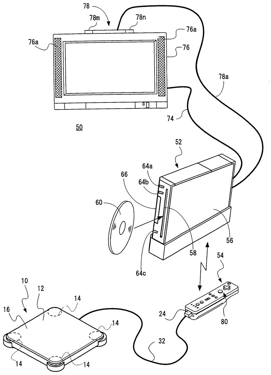
FIG. 4shows an example of a game system or game apparatus50in which the game controller10is used. With reference toFIG. 4, the game system50includes a video game machine (hereinafter simply referred to as “game machine”)52and a controller54. Although not shown, the game machine52of the embodiment is designed to be able to conduct communication with up to four controllers54. The game machine52and the controllers54are wirelessly connected. For example, the wireless communication is conducted pursuant to Bluetooth (registered trademark) standard. However, the wireless communication may be conducted pursuant to other standards such as an infrared ray and wireless LAN. In another embodiment, the controller54may be connected to the game machine52in a wired manner.
The controller54is a game controller, a different type from the game controller10. In the embodiment, the controller54is a main game controller of the game machine52, and the game controller10is prepared as an extended unit of the controller54in order to utilize a wireless communication function of the controller54with the game machine52. The game controller10is connected to the controller54by the connector24that is located at the front end of the cable32extended from the board12. For the purpose of distinction, sometimes the controller54is referred to as “remote control”.
The game machine52includes a housing56having a substantially rectangular solid, and a disk slot58is provided in a front face of the housing56. An optical disk60that is of an example of an information storage medium in which the game program and the like are stored is inserted from the disk slot58and placed on a disk drive62(seeFIG. 5) in the housing56. Although not shown, an LED and a light guide plate can be disposed around the disk slot58to turn on or blink the light of the disk slot58in response to various kinds of processing.
A power button64aand a reset button64bare provided in the front face and in the upper portion of the housing56of the game machine52, and an eject button64cis provided in the front face and in the lower portion of the housing56. An external memory card connector cover66is provided between the reset button64band the eject button64cand near the disk slot58. An external memory card connector68(seeFIG. 5) is provided inside the external memory card connector cover66, and an external memory card (not shown, hereinafter simply referred to as “memory card”) is inserted in the external memory card connector68. The memory card is used to load and temporarily store the game program, etc. from the optical disk60or to store (save) game data (game result or data in the midstream of the game) of the game played using the game system50. However, instead of the storage of the game data in the memory card, the game data may be stored in an internal memory such as a flash memory70(seeFIG. 5) provided inside the game machine52. The memory card may be used as a backup memory of the internal memory. Application except for the game can be performed in the game machine52. In such cases, pieces of data of other applications can be stored in the memory card.
A general-purpose SD card can be used as the memory card, and other general-purpose memory cards such as Memory Stick and MultiMediaCard (registered trademark) can also be used.
Although not shown inFIG. 4, an AV cable connector72(seeFIG. 5) is provided in a rear face of the housing56of the game machine52, and a monitor76and a speaker76aare connected to the game machine52through an AV cable74using the AV connector72. Typically, the monitor76and the speaker76aare a color television receiver, a video signal is inputted from the game machine52to a video input terminal of the color television receiver by the AV cable74, and an audio signal is inputted from the game machine52to an audio input terminal. Accordingly, for example, a game image of a three-dimensional (3D) video game is displayed on a screen of the color television receiver (monitor)76while the stereo game sound such as game music and sound effect is outputted from the right and left speakers76a.A marker unit78including two infrared LEDs (markers)78mand78nis provided around the monitor76(in the embodiment, on the monitor76). The marker unit78is connected to the game machine52through a power cable78a, which allows the electric power to be supplied to the marker unit78from the game machine52. Therefore, the markers78mand78nemit the light to output the infrared light ahead of the monitor76.
The electric power of the game machine52is imparted by a general AC adaptor (not shown). The AC adaptor is inserted in a standard wall socket in home, and the game machine52converts home-use power supply (commercial power supply) into a low DC voltage signal suitable to the drive of the game machine52. In another embodiment, the battery is used as the power supply.
In order that a user or player plays a game (or other applications except for the game) with the game system50, the user turns on the power of the game machine52, then the user appropriately selects the optical disk60in which a program of a video game (or another application to be played) is stored, and the user loads the optical disk60on the disk drive62of the game machine52. Accordingly, the game machine52starts the execution of the video game or another application based on the program recorded in the optical disk60. The user manipulates the remote control54or the game controller10to impart the input to the game machine52. For example, the game or another application can be started by manipulating one of input means80such as various manipulation buttons provided in the remote control54or using the game controller10. In addition to the manipulation of the input means80, the movement of the remote control54itself or the use of the game controller10can move a moving picture object (player object) in a different direction or change a viewpoint (camera position) of the user in the 3D game world.
Alternatively, the program of the video game or another application may be stored (installed) in the internal memory (flash memory70) of the game machine52and executed from the internal memory. In such cases, the program stored in the storage medium such as the optical disk60may be installed in the internal memory or downloaded program may be installed in the internal memory.
FIG. 5is a block diagram showing an example of an electric configuration of the game system50of the embodiment shown inFIG. 4. Although not shown, each component in the housing56is mounted on a printed board. As shown inFIG. 5, a CPU82is provided in the game machine52to act as a game processor. A system LSI84is connected to the CPU82. An external main memory86, a ROM/RTC88, and the disk drive62, and an AVIC90are connected to the system LSI84.
The external main memory86is used to store the programs such as the game program or various kinds of data, and the external main memory86is used as a work area or a buffer area of the CPU82. The ROM/RTC88is a so-called boot ROM into which a program starting up the game machine52is incorporated, and a time circuit is provided to count time in the ROM/RTC88. The disk drive62reads the program or texture data or the like from the optical disk60, and the disk drive62writes the program or texture data or the like in an internal main memory84eor an external main memory86under the control of the CPU82.
An input and output processor84a, a GPU (Graphics Processor Unit)84b, a DSP (Digital Signal Processor)84c, a VRAM84d, and an internal main memory84eare provided in the system LSI84and connected to one another by an internal bus (not shown).
The input and output processor (I/O processor)84aperforms the transmission and reception of the data or the download of the data.
The GPU84bconstitutes a part of a drawing means and receives a graphics command (graphics generation command) from the CPU82to generate game image data according to the command. In addition to the graphics command, the CPU82imparts an image producing program necessary to produce the game image data to the GPU84b.
Although not shown, as described above, the VRAM84dis connected to the GPU84b. The GPU84baccesses the VRAM84dto obtain the data (image data such as polygon data and texture data) necessary to execute the graphics generation command. The CPU82writes the image data necessary for the graphics generation in the VRAM84dthrough the GPU84b. The GPU84baccesses the VRAM84dto produce the game image data for drawing.
In the embodiment, the explanation will be made in a case where the GPU84bproduces the game image data. However, in a case where any application except for the game application is executed, the GPU84bproduces the image data for the application.
The DSP84cacts as an audio processor that produces audio data corresponding to the sound, voice, or music outputted from the speaker76ausing sound data or sound waveform (tone) data stored in the internal main memory84eor external main memory86.
The game image data and audio data produced in the above-described ways are read by the AVIC90and outputted to the monitor76and speaker76athrough the AV connector72. Accordingly, a game screen is displayed on the monitor76, and the sound (music) necessary for the game is outputted from the speaker76a.
A flash memory70, a wireless communication module92, and a wireless controller module94are connected to the input and output processor84a. An extended connector96and the memory card connector68are also connected to the input and output processor84a. An antenna92ais connected to the wireless communication module92and an antenna94ais connected to the wireless controller module94.
The input and output processor84acan conduct communication with another game apparatus and various servers connected to a network through the wireless communication module92. However, the input and output processor84acan directly conduct communication with another game apparatus without the network. The input and output processor84aperiodically accesses the flash memory70to detect the presence or absence of data (referred to as “transmission data”) necessary to be transmitted to the network, and the input and output processor84acan transmit the transmission data to the network through the wireless communication module92and antenna92awhen the transmission data exists. The input and output processor84areceives data (referred to as “reception data”) transmitted from another game apparatus through the network, antenna92a, and wireless communication module92, and the input and output processor84acan store the reception data in the flash memory70. However, the reception data is directly destroyed in the case where the reception data does not satisfy a predetermined condition. The input and output processor84areceives data (referred to as “download data”) downloaded from a download server through the network, antenna92a, and wireless communication module92, and the input and output processor84acan store the download data in the flash memory70.
The input and output processor84areceives the input data (manipulation data) transmitted from the remote control54through the antenna94aand wireless controller module94, and the input and output processor84astores (temporarily stores) the input data in the buffer area in the internal main memory84eor external main memory86. The input data is erased from the buffer area after used in processing (for example, game processing) of the CPU82.
In the embodiment, as described above, the wireless controller module94conducts communication with the remote control54pursuant to the Bluetooth standard.
Moreover, the extended connector96and the memory card connector68are connected to the input and output processor84a. The extended connector96is a connector used for an interface such as a USB and an SCSI, and a medium such as an external storage medium or a peripheral device such as a controller different from the remote control54can be connected to the extended connector96. The wired LAN can also be used instead of the wireless communication module92by connecting a wired LAN adaptor to the extended connector96. An external storage medium such as the memory card can be connected to the memory card connector68. Accordingly, the input and output processor84acan access the storage medium to store or read the data through the extended connector96or memory card connector68.
Although the detailed description is omitted, the power button64a, the reset button64b, and the eject button64care provided in the game machine52(housing56) as shown inFIG. 4. The power button64ais connected to the system LSI84. When the power button64ais turned on, the electric power is supplied to each component of the game machine52through the AC adaptor (not shown), and the system LSI84is set to a mode (referred to as “normal mode”) in which a normal electric conduction state is established. On the other hand, when the power button64ais turned off, the electric power is supplied only to a part of the components of the game machine52, and the system LSI84is set to a mode (hereinafter referred to as “standby mode”) in which the power consumption is kept at a minimum level. In the case where the standby mode is set, the system LSI84provides an instruction to stop the electric power supply to the components except for the input and output processor84a, the flash memory70, the external main memory86, the ROM/RTC88, the wireless communication module92, and the wireless controller module94. Accordingly, in the standby mode, the CPU82does not execute the application.
Although the electric power is supplied to the system LSI84even in the standby mode, the GPU84b, the DSP84c, and the VRAM84dare not driven to reduce the power consumption by stopping clock supply to the GPU84b, the DSP84c, and the VRAM84d.
Although not shown, a fan is provided in the housing56of the game machine52to discharge heat of ICs such as the CPU82and the system LSI84to the outside. The fan is also stopped in the standby mode.
In the case where the standby mode is not utilized, the electric power supply is completely stopped to all the circuit components by selecting a setting in which the standby mode is not utilized, when the power button64ais turned off.
The switch between the normal mode and the standby mode can remotely be performed by the switch of on/off of a power switch80h(seeFIG. 6) of the remote control54. In the case where the remote manipulation is not performed, a setting in which the electric power is not supplied to the wireless controller module94amay be established in the standby mode.
The reset button64bis also connected to the system LSI84. When the reset button64bis pressed, the system LSI84restarts a start-up program of the game machine52. The eject button64cis connected to the disk drive62. When the eject button64cis pressed, the optical disk60is ejected from the disk drive62.
FIGS. 6(A) to 6(E)show an example of an appearance of the remote control54.FIG. 6(A)shows a front-end surface of the remote control54,FIG. 6(B)shows an upper surface of the remote control54,FIG. 6(C)shows a right side face of the remote control54,FIG. 6(D)shows a lower surface of the remote control54, andFIG. 6(E)shows a rear-end surface of the remote control54.
With reference toFIGS. 6(A) to 6(E), the remote control54has a housing98formed by, e.g., plastic molding. The housing98is formed in a substantially rectangular solid, and the housing98has a size that can be grasped by a single hand of the user. Input means (a plurality of buttons and switches)80are provided in the housing98(remote control54). Specifically, as shown inFIG. 6(B), a cross key80a, a (1) button80b, a (2) button80c, an A button80d, a (−) button80e, a HOME button80f, a (+) button80g, and the power button80hare provided in an upper surface of the housing98. As shown inFIGS. 6(C) and 6(D), an inclined surface is provided in a lower surface of the housing98, and a B trigger switch80iis provided in the inclined surface.
The cross key80ais a four-directional push switch, and the cross key80aincludes manipulation portions of four directions shown by arrows, i.e., forward (or upward), backward (or downward), rightward, and leftward directions. For example, the player can provide the instruction of moving direction of a manipulable character or object (player character or player object) or cursor by manipulating one of the manipulation portions.
The (1) button80band the (2) button80care push-button switches. For example, the (1) button80band the (2) button80care used in the game manipulation such that the viewpoint position or the viewpoint direction, i.e, the position or a view angle of a virtual camera are adjusted when the three-dimensional game image is displayed. Alternatively, the (1) button80band the (2) button80cmay be used to perform the same manipulations as the A button80dand B trigger switch80ior a supplementary manipulation.
The A button switch80dis a push-button switch used to cause the player character or player object to perform motions except for the directional instruction, i.e., any action such as punch, throw, grasp (obtaining), ride, and jump. For example, in an action game, the user can provide the instructions such as the jump, punch, and movement of a weapon. In a role-playing game (RPG) or a simulation RPG, the user can provide the instructions such as obtaining of an item and selection and determination of the weapon or command. The A button switch80dis also used to instruct the determination of an icon indicated by a pointer (indicated image) or a button image on the game screen. For example, when the icon or button image is determined, the instruction or command (game command) previously set corresponding to the icon or button image can be inputted.
Similarly, the (−) button80e, the HOME button80f, the (+) button80g, and the power button80hare push-button switches. For example, the (−) button80eis used to select a game mode. The HOME button80fis used to display a game menu (menu screen). The (+) button80gis used to start (resume) the game or suspend the game. The power switch80his used to remotely turn on/off the power of the game machine52.
In the embodiment, a power switch for turning on/off the remote control54itself is not provided. The remote control54is turned on by manipulating one of the input means80of the remote control54, and the remote control54is automatically turned off unless manipulated for over a predetermined time (for example, 30 seconds).
The B trigger switch80iis also a push-button switch, and is mainly used to perform the input emulating a trigger such as shooting or specify the position selected by the remote control54. When the B trigger switch80iis continuously pressed, the motion or a parameter of the player object can be kept at a constant state. In a certain state, the B trigger switch80iacts as the normal B button, and the B trigger switch80iis used to delete the action or command or the like determined by the A button80d.
As shown inFIG. 6(E), an external extended connector100is provided in a rear end face of the housing98, and an indicator102is provided in the upper surface of the housing98and on the rear end face side as shown inFIG. 6(B). The external extended connector100is used to connect an extended controller different from the remote control54. The indicator102includes, e.g. four LEDs. The indicator102can indicate identification information (controller number) of the remote control54according to the lit LED by lighting on one of the four LEDs. The indicator102can also indicate a remaining battery level of the remote control54by the number of lit LEDs.
The remote control54includes an imaging information computation unit104(seeFIG. 7), and a light incident port106of the imaging information computation unit104is provided in a front-end face of the housing98as shown inFIG. 6(A). The remote control54includes a speaker108(seeFIG. 7), and the speaker108is provided in the housing98according to a sound release hole110provided in the upper surface of the housing98and between the (1) button80band the HOME button80fas shown inFIG. 6(B).
The shape of the remote control54and the shape, the quantity, and the installation position, etc. of each input means80are shown inFIGS. 6(A) to 6(E)only by way of example, and which may be changed as appropriate.
FIG. 7is a block diagram showing an example of the electric configuration of the remote control54. With reference toFIG. 7, the remote control54includes a processor112, and the external extended connector100, the input means80, a memory114, an acceleration sensor116, a wireless module118, the imaging information computation unit104, the LED120(indicator102), a vibrator122, the speaker108, and a power supply circuit124are connected to the processor112by an internal bus (not shown). An antenna118ais connected to the wireless module118.
A power supply circuit124supplies the electric power to each component of the remote control54. Typically the power supply circuit124is a battery exchangeably accommodated in the housing98. The power supply circuit124can also supply the electric power to the extended units (such as the game controller10) connected through the external extended connector100.
Although not shown inFIG. 7for the purpose of simple explanation, the indicator102includes the four LEDs120as described above.
The processor112controls the whole of the remote control54. The processor112transmits (inputs) pieces of information (input information) inputted by the input means80, acceleration sensor116, and imaging information computation unit104and pieces of information (such as data from the game controller10) obtained through the external extended connector100to the game machine52through the wireless module118and antenna118ain the form of the input data (manipulation data). At this point, the processor112uses the memory114as the work area or buffer area. The manipulation signals (pieces of manipulation data) from the input means80(80ato80i) are inputted to the processor112, and the processor112temporarily stores the pieces of manipulation data in the memory114.
The acceleration sensor116detects acceleration in each of three axes of a longitudinal direction (y-axis direction), a crosswise direction (x-axis direction), and a fore-and-aft direction (z-axis direction) of the remote control54. Typically, an electrostatic capacity type acceleration sensor is used as the acceleration sensor116. However, different type acceleration sensor may be used.
For example, the acceleration sensor116detects the acceleration (ax, ay, az) for the x-axis, y-axis, and z-axis at first predetermined time intervals, and the acceleration sensor116inputs the detected acceleration data to the processor112. For example, the acceleration sensor116detects the acceleration in each axial direction in a range of −2.0 g to 2.0 g (g is gravitational acceleration, hereinafter the same). The processor112detects the acceleration data imparted from the acceleration sensor116at second predetermined time intervals, and the processor112temporarily stores the acceleration data in the memory114.
The processor112produces input data (manipulation data) including at least one of the manipulation data, the acceleration data, and later-mentioned marker coordinate data, and the processor112transmits the produced input data to the game machine52at third predetermined time intervals (for example, 5 ms). The processor112can add the data received from the game controller10through the external extended connector100to the input data.
Although not shown inFIGS. 6(A) to 6(E), in the embodiment, the acceleration sensor116is provided near the position where the cross key80ais disposed on the board in the housing98.
At this point, those skilled in the art easily understand from the description of the present invention that the computer such as the processor (for example, CPU82) of the game machine52and the processor (for example, processor112) of the remote control54can perform processing to estimate or compute (determine) further information on the remote control54based on the acceleration data outputted from the acceleration sensor116.
For example, in the case where the uni-axial acceleration sensor116is mounted on the remote control54to perform the processing on the computer side while the remote control54is assumed to be in the static state, namely, in the case where the processing is performed while the acceleration detected by the acceleration sensor116is assumed to be formed only by the gravitational acceleration, whether or not an attitude of the remote control54is inclined with respect to the gravitational direction or how much the attitude of the remote control54is inclined with respect to the gravitational direction can be understood based on the detected acceleration data when the remote control54is actually in the static state. Specifically, on the basis of the state in which the acceleration sensor116has a vertically-downward detection axis, whether or not the attitude of the remote control54is inclined by the application of 1 g (gravitational acceleration) and how much the attitude of the remote control54is inclined by a magnitude of the acceleration can be understood.
In the case where the multi-axis acceleration sensor116is mounted on the remote control54, how much the attitude of the remote control54is inclined with respect to the gravitational direction can be understood in detail by performing processing to the acceleration data of each axis. In this case, the processor112may perform processing for computing data of an inclination angle of the remote control54based on the output of the acceleration sensor116, or processing for roughly estimating the inclination may be performed without performing the processing for computing the data of the inclination angle based on the output from the acceleration sensor116. Thus, the inclination, attitude, or position of the remote control54can be determined by the combination of the acceleration sensor116and the processor112.
On the other hand, assuming that the acceleration sensor116is in a dynamic state, because the acceleration is detected according to the motion of the acceleration sensor in addition to the gravitational acceleration component, the direction of the motion and the like can be understood when the gravitational acceleration component is removed by predetermined processing. Specifically, in the case where the remote control54on which the acceleration sensor116is mounted is moved by the user while dynamically accelerated, various motions and/or positions of the remote control54can be computed by processing the acceleration data produced by the acceleration sensor116.
Even if the acceleration sensor116is assumed to be in the dynamic state, the inclination can be understood with respect to the gravitational direction when the acceleration corresponding to the motion of the acceleration sensor116is removed by predetermined processing. In another embodiment, the acceleration sensor116may include a built-in signal processing unit or another dedicated processing unit in order to perform desired processing to the acceleration signal (acceleration data) outputted from the built-in acceleration detection means before the acceleration data is outputted from the processor112. For example, in the case where the acceleration sensor116is used to detect the static acceleration (for example, gravitational acceleration), the built-in or dedicated processing unit may convert the detected acceleration data into the corresponding inclination angle (or other preferable parameter).
The wireless module118uses, e.g., the Bluetooth technique to modulate a carrier wave having a predetermined frequency using the input data, and the wireless module118radiates the weak radio signal from the antenna118a. That is, the input data is modulated into the weak radio signal by the wireless module118and transmitted from the antenna118a(remote control54). The weak radio signal is received by the wireless controller module94provided in the game machine52. Demodulation and decoding are performed to the received weak radio signal, which allows the game machine52(CPU82) to obtain the input data from the remote control54. The CPU82can perform the application processing (game processing) according to the obtained input data and the application program (game program).
As described above, the imaging information computation unit104is provided in the remote control54. The imaging information computation unit104includes an infrared filter104a, a lens104b, an imaging device104c, and an image processing circuit104d. The infrared filter104atransmits only the infrared ray in the light incident from ahead of the remote control54. As described above, the markers78mand78ndisposed near (around) the display screen of the monitor76are infrared LEDs that output the infrared ray ahead of the monitor76. Accordingly, the images of the markers78mand78ncan be taken more exactly by providing the infrared filter104a. The infrared ray transmitted through the infrared filter104ais outputted to the imaging device104cthrough the lens104b. The imaging device104cis a solid-state imaging device, such as a CMOS sensor or a CCD, which images the infrared ray collected by the lens104b. Accordingly, the imaging device104cimages only the infrared ray transmitted through the infrared filter104ato produce the image data. Hereinafter the image taken by the imaging device104cis referred to as taken image. The image data produced by the imaging device104cis processed by the image processing circuit104d. The image processing circuit104dcomputes the position of the imaging target (markers78mand78n) in the taken image and outputs each coordinate value indicating the position as imaging data (later-mentioned marker coordinate data) to the processor112at fourth predetermined time intervals. The processing performed in the image processing circuit104dis described later.
FIG. 8is an illustrative view roughly explaining a state in which the game is played using the remote control54in the video game system50. As shown inFIG. 8, the player grasps the remote control54in one hand. Exactly, in the case where the pointing function of the remote control54is used, the player grasps the remote control54while the front-end surface (the side of the incident port106to which the light imaged by the imaging information computation unit104is incident) of the remote control54is orientated toward the markers78mand78n. However, as can be seen fromFIG. 4, the markers78mand78nare disposed in parallel with the crosswise direction of the screen of the monitor76. In this state of things, the player changes the position on the screen indicated by the remote control54or the distance between the remote control54and the marker78mor78nto perform the game manipulation.
FIG. 9is an illustrative view for explaining view angles of the markers78mand78nand remote control54. As shown inFIG. 9, the markers78mand78neach emit the infrared ray in a range of a view angle θ1. The imaging device104cof the imaging information computation unit104can receive the incident light in a range of a view angle θ2around a visual axis direction of the remote control54. For example, each of the markers78mand78nhas the view angle θ1of 34° (half-value angle), and the imaging device104chas the view angle θ2of 41°. The player grasps the remote control54such that the imaging device104cis set to the position and orientation at which the infrared rays can be received from the two markers78mand78n. Specifically, the player grasps the remote control54such that at least one of the markers78mand78nexists in the view angle θ2of the imaging device104cwhile the remote control54exists in the view angle θ1of at least one of the markers78mand78n. In this state, the remote control54can detect at least one of the markers78mand78n. The player can change the position and orientation of the remote control54to perform the game manipulation in the range satisfying this state. In the case where one of the markers78mand78nis detected, for example, a tentative marker coordinate is set instead of the marker that is not detected by utilizing the immediately preceding pieces of data in which the two markers78mand78nare detected, allowing the computation of the position indicated by the remote control54.
In the case where the position and orientation of the remote control54are out of the range, the game manipulation cannot be performed based on the position and orientation of the remote control54. Hereinafter the range is referred to as “manipulable range”.
In the case where the remote control54is grasped in the manipulable range, the images of the markers78mand78nare taken by the imaging information computation unit104. That is, the taken image obtained by the imaging device104cincludes the images (target images) of the markers78mand78nthat are of the imaging target.FIG. 10is a view showing an example of the taken image including the target image. Using the image data of the taken image including the target image, the image processing circuit104dcomputes the coordinate (marker coordinate) indicating the position in the taken images of the markers78mand78n.
Because the target image appears as a high-brightness portion in the image data of the taken image, the image processing circuit104ddetects the high-brightness portion as a candidate of the target image. Then, the image processing circuit104ddetermines whether or not the high-brightness portion is the target image based on the size of the detected high-brightness portion. Sometimes the taken image includes not only images78m′ and78n′ corresponding to the two markers78mand78nthat are of the target image but also the image except for the target image due to the sunlight from a window or a fluorescent light. The processing of the determination whether or not the high-brightness portion is the target image is performed in order to distinguish the images78m′ and78n′ that are of the target image from other images to exactly detect the target image. Specifically, the determination whether or not the detected high-brightness portion has the size within a predetermined range is made in the determination processing. When the high-brightness portion has the size within the predetermined range, it is determined that the high-brightness portion indicates the target image. On the contrary, when the high-brightness portion does not have the size within the predetermined range, it is determined that the high-brightness portion indicates the image except for the target image.
Then, the image processing circuit104dcomputes the position of the high-brightness portion for the high-brightness portion in which it is determined as a result of the determination processing that the high-brightness portion indicates the target image. Specifically, a barycentric position of the high-brightness portion is computed. Hereinafter the coordinate of the barycentric position is referred to as marker coordinate. The barycentric position can be computed in more detail compared with resolution of the imaging device104c. At this point, it is assumed that the image taken by the imaging device104chas the resolution of 126×96 and the barycentric position is computed in a scale of 1024×768. That is, the marker coordinate is expressed by an integer number of (0, 0) to (1024, 768).
The position in the taken image is expressed by a coordinate system (XY-coordinate system) in which an origin is set to an upper left of the taken image, a downward direction is set to a positive Y-axis direction, and a rightward direction is set to a positive X-axis direction.
In the case where the target image is correctly detected, two marker coordinates are computed because the two high-brightness portions are determined as the target image by the determination processing. The image processing circuit104doutputs the pieces of data indicating the two computed marker coordinates. As described above, the outputted pieces of marker coordinate data are added to the input data by the processor112and transmitted to the game machine52.
When the game machine52(CPU82) detects the marker coordinate data from the received input data, the game machine52can compute the position (indicated coordinate) indicated by the remote control54on the screen of the monitor76and the distances between the remote control54and the markers78mand78nbased on the marker coordinate data. Specifically, the position toward which the remote control54is orientated, i.e., the indicated position is computed from the position at the midpoint of the two marker coordinates. When the coordinate of the position indicated by the remote control54is computed from the marker coordinate, the coordinate system of the taken image ofFIG. 10is appropriately converted into the coordinate system for expressing the position on the screen.
In the embodiment, the remote control54performs the predetermined computation processing to the imaging data to detect the marker coordinate, and the marker coordinate data is transmitted to the game machine52. Alternatively, in another embodiment, the imaging data is transmitted as the input data from the remote control54to the game machine52, and the CPU82of the game machine52may perform the predetermined computation processing to the imaging data to detect the marker coordinate and the coordinate of the indicated position.
The distance between the target images in the taken image is changed according to the distances between the remote control54and the markers78mand78n. The distance between the markers78mand78n, a width of the taken image, and the view angle θ2of the imaging device104care previously determined, so that the game machine52can compute the current distances between the remote control54and the markers78mand78nby computing the distance between the marker coordinates.
In the game system50, the game controller10is used for the game manipulation by the load applied by the player. The connector24of the game controller10is connected to the external extended connector100of the remote control54, thereby connecting the game controller10and the remote control54. This enables the game controller10to transmit and receive the data to and from the game machine52through the remote control54.
As described above, the game controller10can detect the load only when the game machine52requires the load. Specifically, when the game machine52requires the load detected by the game controller10, the CPU82of the game machine52wirelessly transmits the load obtaining command for the game controller10to the remote control54. When the processor112of the remote control54receives the load obtaining command from the game machine52, the processor112transmits the load obtaining command to the game controller10through the external extended connector100. When the microcomputer20of the game controller10receives the load obtaining command through the connector24and cable32, the microcomputer20controls the DC-DC converter26to supply the electric power to the load sensor14, amplifier28, and AD converter22. Therefore, the signal indicating the load applied to each load sensor14is outputted, and the signal is amplified by each amplifier28and imparted to the AD converter22. The AD converter22converts the signal into the digital data and outputs the digital data to the microcomputer20. Accordingly, the microcomputer20can obtain the load detection value data detected by each of the four load sensors14.
The microcomputer20transmits the obtained load detection value data to the remote control54through the cable32and connector24. The load detection value data may directly be transmitted, or the load detection value data may be transmitted after predetermined computation processing is performed to the detection value or computation processing is performed according to the load obtaining command. The processor112of the remote control54stored the load detection value data in the memory114when receiving the load detection value data from the game controller10through the external extended connector100. The processor112produces the input data (manipulation data) including the load detection value data and transmits the input data to game machine52through the wireless module118. The CPU82of the game machine52obtains the load value of the game controller10from the received input data, and the CPU82can use the load value for the game processing. Accordingly, the player can perform various game manipulations by the load applied to the game controller10.
FIG. 11is an illustrative view roughly explaining a state in which the game is played using the game controller10. The devices except for the board12of the game controller10and the monitor76are omitted inFIG. 11. In playing the game with the load, typically the player puts the player's legs on the board12of the game controller10as shown inFIG. 11. The four load sensors14detect the loads applied to the game controller10by the player, and the load detection value that is of the manipulation data by the player is transmitted to the game machine52. The load value detected by each load sensor14depends on the position where the player rides on the board12. The load value detected by each load sensor14is changed according to the change in load when the player moves the body on the board12or when the player changes the loads applied to the right and left legs or the like. In the game machine52, the game processing is performed based on the load applied by the player. Accordingly, the player can play the game by performing the game manipulation for appropriately applying the load such as the change in position where the player rides on the board12and the movement of the body.
For example, in the case of a game performed based on the simple total value of the four load values detected by the four load sensors14, the player can take any position with respect to the four load sensors14of the game controller10, that is, the player can play the game while riding on any position of the board12with any orientation. However, depending on the type of the game, it is necessary to perform processing while determining toward which direction the load value detected by each load sensors14is orientated when viewed from the player. That is, it is necessary to understand a positional relationship between the four load sensors14of the game controller10and the player. For example, the positional relationship between the four load sensors14and the player is previously defined, and it may be assumed that the player rides on the board12such that the predetermined positional relationship is obtained. Typically, there is defined such the positional relationship that each two load sensors14exist at the front and the back of and on right and left sides of the player riding on the center of the board12, i.e. such the positional relationship that the load sensors14exist in the right front, left front, right rear, and left rear directions from the center of the player respectively when the player rides on the center of the board12of the game controller10. In the typical game in which the screen of the monitor76is located at the front of the player, as shown inFIG. 11, the game controller10is disposed such that a predetermined one side of the board12is located on the side of the monitor76in parallel with the screen. Therefore, the above-described predetermined positional relationship is easily obtained, and the load value of each load sensor14becomes the load value in the predetermined direction when viewed from the player.
A spot may be provided in the board12in order to provide information on such the arrangement of the game controller10that the predetermined positional relationship is obtained to the player. For example, in order that the two adjacent load sensors14in predetermined one side of the board12are disposed at the front of the player, i.e., on the side of the monitor76, the spot may be provided in a predetermined portion such as the upper surface or side face along the predetermined one side of the board12. Alternatively, the cable32of the connector24is configured to be extracted from a predetermined portion in the side face or lower surface along the predetermined one side of the board12, and the position from which the cable32is extracted may be set to the spot.
The game controller10and the game machine52can understand that the load detection values correspond to which direction when viewed from the player based on the identification information on each load sensor14included in the load detection value data and the previously-set (stored) information on the arrangement of the load sensors14. Accordingly, the intention of the game manipulation, such as the front, rear, right, and left manipulation directions, which is performed by the player can be understood.
The arrangement of the load sensors14relative to the player is not previously defined but the arrangement may be set by the player's input in the initial setting or the like. For example, the load is obtained while the screen in which the player instructed to ride on the portion in a predetermined direction (such as the right front, left front, right rear, and left rear directions) when viewed from the player. Therefore, the positional relationship between each load sensor14and the player can be specified, and the information on the arrangement by the setting can be generated and stored.
A positional relationship in which the load sensors14exist at the front and back of and on right and left sides of the player respectively may be assumed in another embodiment. In this case, the game controller10is disposed such that one predetermined corner of the board12exists on the side of the monitor76while a predetermined diagonal line is parallel to the screen. The spot may be provided in the upper surface or side face at the one predetermined corner of the board12.
In the game system50, the quantity of load values necessary to the game processing is determined, and the determined quantity of load values is computed from the four load detection values. The game processing is performed based on the necessary quantity of load computation values. Because the necessary quantity of load values is computed from the four load detection values to perform the game processing, a novel game with the game controller10including the load sensor14can be proposed to perform various games.
In the embodiment, the game is performed such that the necessary quantity of load values is kept constant.FIGS. 12 to 14show screens of the three games of the embodiment.
FIG. 12shows the screen of the game in which the one load value is required. In the game, one load value is computed from the four load detection values and the game processing is performed based on the load value. The game is called a total load game (total load mode) and based on the summation (total load value) of the four load detection values. An example of the total load game is a squat game in which the player does the squat (knee bending) on the board12. For example, a message of “Do squat!” is displayed on the screen, and the player is required to do the squat as many as possible within a time-limit. The determination whether or not the player is successful in the squat is made based on the total load value. For example, a waveform indicating a temporal change in total load value is shown by a graph. When the waveform is changed in a predetermined shape, it is determined that the player is successful in the squat, and the character of success and the number of successful times are displayed on the screen. When the waveform is not changed in the predetermined shape, it is determined that the player fails in the squat, and the character of failure is displayed. A score is given to the player according to the number of successful times within the time-limit.
FIG. 13shows the screen of the game in which the two load values are required. In the game, two load values are computed from the four load detection values and the game processing is performed based on the two load values. The game is called right and left balance game (right and left balance mode) played by the balance of the player in the right and left directions. Specifically, as shown in the lower portion ofFIG. 13, the four load sensors14of the game controller10are divided into two sets of the right set including the two load sensors14and the left set including the two load sensors14. The player's legs are schematically shown by the two shapes shown by the dotted line on the game controller10for the purpose of easy understanding of the positional relationship between the player and the four load sensors14. The numeral14adesignates the load sensor14located in the upper left (left front) of the player, the numeral14bdesignates the load sensor14located in the lower left (left rear) of the player, the numeral14cdesignates the load sensor14located in the upper right (right front) of the player, and the numeral14ddesignates the load sensor14located in the lower right (right rear) of the player. The load values of the two sets are computed. That is, the summation (left load value) of the load detection values of the load sensors14aand14bon the left side of the player and the summation (right load value) of the load detection values of the load sensors14cand14don the right side of the player are computed. In the game, the player is required to keep the right and left balance such that the right load value and the left load value are kept within each predetermined range for a predetermined time. A message of “Stop motion in a frame for three seconds!”, a bar graph indicating the right load value, a bar graph indicating the left load value, and two frames indicating target ranges of the right and left load values are shown on the screen. When the upper end of the bar indicating each load value is falls within each frame for three seconds, the game is cleared and a score is given to the player.
FIG. 14shows the screen of the game in which the four load values are required. In the game, the four load values are computed from the four load detection values and the game processing is performed based on the four load values. The game is called four-directional balance game (four-directional balance mode) played by the balance of the player in the vertical and horizontal directions. As used herein, the vertical direction of the player shall mean the fore-and-aft direction of the player. Specifically, as shown in the lower portion ofFIG. 14, the load values are computed in the vertical and horizontal directions of the player. That is, the summation (upper load value) of the load detection values of the load sensors14aand14con the upper side of the player, the summation (lower load value) of the load detection values of the load sensors14band14don the lower side of the player, the summation (left load value) of the load detection values of the load sensors14aand14bon the left side of the player, and the summation (right load value) of the load detection values of the load sensors14cand14don the right side of the player are computed. In the game, the player is required to keep the vertical and horizontal balances such that the upper load value, the lower load value, the right load value, and the left load value are kept within each predetermined range for a predetermined time. Similarly to the right and left balance game, a message, four bar graphs indicating the load values, and four frames indicating target ranges of the load values are shown on the screen. When the upper end of the bar indicating each load value is falls within each frame for three seconds, the game is cleared and a score is given to the player.
FIG. 15shows an example of a memory map of the game machine52. The memory map includes a program memory area200and a data memory area202. The program and part of pieces of data are read at once from the optical disk60or read partially and sequentially if needed, and the program and part of pieces of data are stored in the external main memory86.FIG. 15only shows a part of the memory map, and other program and pieces of data necessary for the processing are also stored. For example, the sound data for outputting the sound such as the voice, sound effect, and music, the image data for producing the screen, the sound output program, and the image producing display program are read from the optical disk60and stored in the data memory area202or program memory area200. In the embodiment, the program and part of pieces of data are read from the optical disk60. However, in another embodiment, the program and pieces of data previously stored in a nonvolatile storage medium such as the flash memory70incorporated in the game machine52may be read and stored in the external main memory86. At this point, the program downloaded through the network may be stored in the storage medium using the wireless communication module92of the game machine52or the communication module connected to the extended connector96.
A game selection program is stored in a memory area204. The game selection program is used to select the game (mode) to be performed. For example, one game is selected from the plurality of games (the total load game, the right and left balance game, and the four-directional balance game) by the input of the player. In the case where the selection is made by the player input, a game selection screen having icons corresponding to the plurality of games is displayed, and the icon is selected by the position indication using the imaging information computation unit104of the remote control54, the indication using the cross key80a, or the indication using the game controller10, or the like. Alternatively, the game may be selected according to the performance order previously determined in the program or the game may randomly be selected.
A command transmission program is stored in a memory area206. The command transmission program is used to transmit the load obtaining command to the game controller10. The load obtaining command is transmitted when the load value is required (load obtaining timing). The load obtaining timing may be set so as to come at regular time intervals, or the load obtaining timing may be set only when a predetermined game status or an event is generated. When the game controller10receives the load obtaining command, in the game controller10, the load is detected by the load sensor14and the load detection value is transmitted to the game machine52.
A load detection value obtaining program is stored in a memory area208. The load detection value obtaining program is used to receive and obtain the load detection value transmitted from the game controller10.
A correction program is stored in a memory area210. The correction program is used to correct the obtained load detection value. For example, even if the player believes that the player rides on the center of the board12, namely, even if the player believes the player rides on the board12such that the barycenter is located in the center of the board12, sometimes a variation in load values detected by the four load sensors14is generated depending on individual characteristics such as the attitude of the player, a standing position, a physical feature (such as difference in length of the legs), and a habit. Accordingly, in the embodiment, the load detection value is appropriately corrected to accurately recognize the game manipulation by the load of the player. The correction is performed based on difference of the load detection values of the four load sensors14. Specifically, the detection value is corrected based on a correction value computed by a correction value computing program described below.
The correction value computing program is stored in a memory area212. The correction value computing program is used to compute the correction value for correcting the load detection value. The correction value computation is performed by the initial setting before the game is started. For example, the image in which the player is instructed to ride on the center of the board12of the game controller10is displayed on the monitor76, and the four load detection values detected by the four load sensors14are obtained. The two kinds of the differences are computed in the different combinations from the four load detection values, and the correction value is computed based on the two kinds of the differences. Specifically, the four load sensors14are divided into first two sets, i.e., into the right and left, the right load value and the left load value are computed, and a first difference is computed by taking the difference between the right load value and the left load value. A first correction value is computed to correct each of the load detection values divided into the right and left based on the first difference. The four load sensors14are divided into second two sets, i.e., into the upper and lower portions, the upper load value and the lower load value are computed, and a second difference is computed by taking the difference between the upper load value and the lower load value. A second correction value is computed to correct each of the load detection values divided into the upper and lower portions based on the second difference. Then, a final correction value of each load detection value is computed based on the first difference and the second difference. Each load detection value is corrected based on each final correction value.
For example, assuming that the left load has the value of 60 and the right load has the value of 40, the first difference becomes 20, and the first correction value is computed by equally dividing the first difference into four. That is, the first correction value for the upper left load sensor14aand lower left load sensor14bbecomes −5 (=−20/4), and the first correction value for the upper right load sensor14cand lower right load sensor14dbecomes 5(=20/4). Assuming that the upper load has the value of 30 and the lower load has the value of 70, the second difference becomes 40, and the second correction value is computed by equally dividing the second difference into four. That is, the second correction value for the upper left load sensor14aand upper right load sensor14cbecomes 10 (=40/4), and the second correction value for the lower left load sensor14band lower right load sensor14dbecomes −10 (=−40/4). The correction values finally set for the four load sensors14are computed based on the first correction value and the second correction value. Specifically, the final correction value is computed by adding the first correction value and the second correction value. That is, the final correction value for the upper left load sensor14abecomes +5 (=−5+10), the final correction value for the lower left load sensor14bbecomes −15 (=−5-10), the final correction value for the upper right load sensor14cbecomes +15 (=5+10), and the final correction value for the lower right load sensor14dbecomes −5 (=5−10).
A necessary quantity determining program is stored in a memory area214. The necessary quantity determining program is used to determine the quantity of load values necessary for the game processing. In the embodiment, because the total load game, the right and left balance game, and the four-directional balance game, etc. as described above are performed, the necessary quantity of load values is determined in each game or game mode or the like, and information such as a quantity table in which the necessary quantity of load values is set in each game or game mode or the like is previously stored. Accordingly, the necessary quantity of load values can be determined by the identification information such as a game name or the type or mode of the game. In another embodiment, the necessary quantity of load values may be changed according to the scene or status or the like of the game. In such cases, the necessary quantity of load values is determined by the scene of the game or the like.
A load value computing program is stored in a memory area216. The load value computing program is used to compute the quantity of load values necessary for the game processing based on the load detection values from the four load sensors14. In the case where the correction is performed by the correction program, the load value is computed based on the corrected load detection value. Specifically, the summation (total load value) of the four load detection values is computed in the case of the total load game, the right and left load values are computed in the case of the right and left balance game, and the left load value, the right load value, the upper load value, and the lower load value are computed in the case of the four-directional balance game. Because the necessary quantity of load values is computed from the four load detection values, the game processing can be performed using various quantities of load values according to the game. Depending on the game, sometimes the load detection value (corrected load detection value) is directly used. In such cases, the load detection value (corrected load detection value) is directly computed as the load computation value.
A game processing program is stored in a memory area218. The game processing program is used to perform the game processing based on the load computation value. In the embodiment, the game processing is performed for the total load game, the right and left balance game, and the four-directional balance game, etc.
A memory area220is an input data buffer in which the pieces of input data (manipulation data) from the game controller10and remote control54are stored. A memory area222is a selection game memory area where the identification information on the game selected by the game selection program is stored.
The load detection values of the four load sensors14obtained from the input data buffer220using the load detection value obtaining program are stored in a memory area224. The correction values, i.e., the final correction values for the four load sensors14computed using the correction value computing program are stored in a memory area226. The load detection values corrected using the correction program are stored in a memory area228.
The quantity table indicating the quantity of load values necessary for the game processing is stored in a memory area230. In the embodiment, the necessary quantity of load values is stored while correlated with the name or type of the game or the like. The load computation value obtained using the load value computing program is stored in a memory area232.
A squat flag is stored in a memory area234. The squat flag indicates status in action or at rest in the total load game. For example, the squat flag is turned on when the change in summation (total load value) of the four load detection values is not lower than a predetermined value. A squat success counter indicating the number of times at which the player is successful in the squat is stored in a memory area236. A time counter is stored in a memory area238. In the squat determination of the total load game, the time counter is used to measure a time for one-time squat. In the right and left balance game and the four-directional balance game, the time counter is used to measure a time during which each load computation value falls within the predetermined target range.
FIG. 16shows an example of the operation of the game controller10. The microcomputer20of the game controller10performs the operation ofFIG. 16at regular time intervals. In a step S1, the microcomputer20determines whether or not the load obtaining command is received from the game machine52. In the embodiment, because the game controller10is connected to the remote control54, the microcomputer20determines whether or not the command of the game machine52is received from the remote control54through the connector24.
If “YES” in the step S1, the microcomputer20controls the DC-DC converter26to supply the electric power to the four load sensors14in a step S3. At the same time, the electric power is also supplied to each amplifier28and the AD converter22. Accordingly, each load sensor14imparts the signal to the AD converter22through each amplifier28according to the detected load, and the AD converter22produces the data indicating the load detection value of each load sensor14and imparts the data to the microcomputer20.
In a step S5, the microcomputer20obtains the load detection values from the four load sensors14. Specifically, the microcomputer20obtains the pieces of data indicating the four load detection values from the AD converter22and stored the pieces of data in an internal memory (not shown).
In a step S7, the microcomputer20transmits the obtained four pieces of load detection value data to the game machine52. In the embodiment, the load detection value data is transmitted to the remote control54through the connector24, and the load detection value data is transmitted from the remote control54to the game machine52.
On the other hand, if “NO” in the step S1, that is when the load obtaining command is not received from the game machine52, the microcomputer20controls the DC-DC converter26to stop the electric power supplied to the four load sensors14in a step S9. The electric power supplied to each amplifier28and the AD converter22is also stopped at the same time. When the step S7or S9is ended, the processing is ended. Thus, in the game controller10, the electric power is supplied from the battery30to the load sensors14and the like only when the load detection is required, so that the power consumption can be suppressed at a lower level.
FIG. 17shows an example of the operation of the remote control54.FIG. 17shows only the processing concerning the load detection of the game controller10in the operations of the processor112, and the processing for obtaining manipulation data using the input means80, acceleration sensor116, and imaging information computation unit104is omitted.
In a step S21, the processor112determines whether or not the load obtaining command is received from the game machine52through the wireless module118. If “YES” in the step S21, the processor112transmits the load obtaining command to the game controller10through the connector100in a step S23. Therefore, in the game controller10, the load value is detected as described above and the load detection value data is transmitted to the remote control54.
When the step S23is ended, or If “NO” in the step S21, the processor112determines whether or not the load detection value data is received from the game controller10through the connector100in a step S25. If “YES” in the step S25, the processor112stores the received four pieces of load detection value data in the memory114in a step S27. In a step S29, the processor112produces the input data (manipulation data) including the four pieces of load detection value data and transmits the input data to the game machine52through the wireless module118. This enables the four load detection values to be imparted from the game controller10to the game machine52. The transmission is performed when the load detection value data is received from the game controller10. Alternatively, the transmission may be performed at a predetermined time the remote control54transmits the input data including the manipulation data of the input means80, the acceleration data detected by the acceleration sensor116, and the marker coordinate data from the imaging information computation unit104. When the step S29is ended or If “NO” in the step S25, the processing is ended.
FIG. 18shows an example of the operation of the game machine52. The flowchart ofFIG. 18shows only the processing concerning the load. Although the CPU82concurrently performs processing for the screen display (update) and processing for outputting the sound and the like at regular time intervals, these pieces of processing are omitted in the flowchart ofFIG. 18.
In a step S41, the CPU82performs correction value computing processing. The correction value computing processing is performed according to the correction value computing program, andFIG. 19shows an example of the detailed operation of the correction value computing processing.
In a step S71ofFIG. 19, the CPU82obtains the load detection values from the four load sensors14. For example, using the GPU84b, the CPU82produces the screen in which the player is instructed to ride on the center of the board12of the game controller10and causes the monitor76to display the screen. Then, the CPU82transmits the load obtaining command to the game controller10through the wireless controller module94. In response to the transmission of the load obtaining command, the load value is detected through the processingFIGS. 16 and 17, and the input data (manipulation data) including the load detection value data is transmitted to the game machine52. Thus, the CPU82can obtain the four pieces of load detection value data from the input data buffer220.
In a step S73, the CPU82computes the summation of the two load detection values on the left side, i.e., the left load value. In a step S75, the CPU82computes the summation of the two load detection values on the right side, i.e., the right load value. In a step S77, the CPU82computes the difference (first difference) between the left load value and the right load value. In a step S79, the CPU82computes the correction values of the load detection values from the four load sensors14based on the computed first difference. The correction value is the first correction value obtained by dividing the four load sensors14into the left and right, and the first correction value is computed by equally dividing the first difference into four and by allocating the equally-divided difference to each load sensor14. Accordingly, absolute values of the first correction values for the load sensors14are equal to one another, and the left side differs from the right side in the sign.
In a step S81, the CPU82computes the summation of the two load detection values on the upper side, i.e., the upper load value. In a step S83, the CPU82computes the summation of the two load detection values on the lower side, i.e., the lower load value. In a step S85, the CPU82computes the difference (second difference) between the upper load value and the lower load value. In a step S87, the CPU82computes the correction values of the load detection values from the four load sensors14based on the computed second difference. The correction value is the second correction value obtained by vertically dividing the four load sensors14into the two sets, and the second correction value is computed by equally dividing the second difference into four and by allocating the equally-divided difference to each load sensor14. Accordingly, absolute values of the second correction values for the load sensors14are equal to one another, and the upper side differs from the lower side in the sign.
In a step S89, the CPU82computes the final correction values of the four load sensors14based on the two computed correction values. Specifically, the first correction value and the second correction value are added to each other for each load sensor14, thereby computing the finally-set correction values. In a step S91, the CPU82writes the final correction value of each of the four load sensors14in the correction value memory area226. When the step S91is ended, the correction value computing processing is ended and the processing returns to a step S43ofFIG. 18.
In the step S43ofFIG. 18, the CPU82performs game selection processing. In the embodiment, as described above, because the total load game, right and left balance game, and four-directional balance game having the different necessary quantities of load values are performed, the game to be performed is selected based on the player's input or a rule previously set to the program or the like. The identification information indicating the selected game is stored in the memory area222.
Then, the CPU82starts the processing for the selected game. In a step S45, the CPU82determines whether or not it is load obtaining timing. The load obtaining timing is a time the load value is required in the game processing. In the case where the load is required at regular time intervals, the processing is configured to determine that it is the load obtaining timing at regular time intervals. Alternatively, the load obtaining timing may be a time at a predetermined event is generated or a time at a predetermined status is generated in the game. The processing in the step S45is performed at regular time intervals until the CPU82determines that it is the load obtaining timing.
If “YES” in the step S45, the CPU82transmits the load obtaining command to the game controller10in a step S47. Specifically, the CPU82transmits the load obtaining command to the remote control54through the wireless controller module94, etc. In response to the transmission of the load obtaining command, the manipulation data including the four pieces of load detection value data is transmitted from the game controller10(remote control54) through the processing performed by the remote control54and the game controller10. The four pieces of load detection value data are received through the wireless controller module94, etc. and stored in the input data buffer220. In a step S49, the CPU82obtains the four pieces of load detection value data from the game controller10. Specifically, the CPU82reads the four pieces of load detection value data from the input data buffer220and stores the four pieces of load detection value data in the load detection value memory area224.
In a step S51, the CPU82corrects the four load detection values based on the correction values stored in the correction value memory area226. Specifically, the CPU82adds the final correction values for the four load sensors14to the four load detection values respectively, and the CPU82stores the computed values in the memory area228for the corrected load detection values.
In steps S53to S57, the CPU82determines the quantity of load values necessary for the game processing. In the embodiment, the necessary quantity of load values is kept constant in each selection game, so that the necessary quantity of load values corresponding to the selection game stored in the memory area222can be specified by referring to the quantity table stored in the memory area230.
In the step S53, the CPU82determines whether or not the necessary quantity of load values is one. If “YES” in the step S53, the CPU82performs the game processing1in a step S59. In the embodiment, the necessary quantity of load values is one in the total load game, andFIG. 20, which will be described later, shows the operation of the game processing1for the total load game.
On the other hand, if “NO” in the step S53, the CPU82determines whether or not the necessary quantity of load values is two in the step S55. If “YES” in the step S55, the CPU82performs the game processing2in a step S61. In the embodiment, the necessary quantity of load values is two in the right and left balance game, andFIG. 21, described later, shows the operation of the game processing2for the right and left balance game.
If “NO” in the step S55, the CPU82determines whether or not the necessary quantity of load values is four in the step S57. If “YES” in the step S57, the CPU82performs the game processing3in a step S63. In the embodiment, the necessary quantity of load values is four in the four-directional balance game, andFIG. 22, described later, shows the operation of the game processing3for the four-directional balance game.
If “NO” in the step S57, the CPU82performs another piece of game processing in a step S65.
A game end determination is made in each game processing. When the game is not ended, the processing returns to the step S45. Accordingly, the pieces of processing from the step S45are repeated and the game advances until the CPU82determines that the game is ended. On the other hand, when the CPU82determines that the game is ended, the game processing in the step S59, S61, S63, or S65is ended.
FIG. 20shows an example of the operation of the game processing1for the total load game in which the necessary quantity of load values is one. When the game processing1is started, the CPU82computes the summation (total load value) of the four load detection values in a step S101. The computation is performed using the corrected load detection values of the memory area228.
In a step S103, the CPU82stores the summation (total load value) in the memory. Specifically, the summation is written in the load computation value memory area232. A history of the summation is stored in the memory area232.
On the basis of the summation, it is determined whether or not the squat is performed. The change in summation is increased while the player does the squat, that is, the change from the previous load obtaining timing becomes a predetermined value or more. Accordingly, when the change in summation is not lower than the predetermined value, it can be determined that the squat is performed, and the summation at that time is recorded. When the squat is finished, the change from the previous load obtaining timing becomes lower than a predetermined value. Accordingly, when the change in summation becomes lower than the predetermined value, it is considered that the one-time squat is finished, and it is determined whether or not the squat is actually performed based on the recorded waveform of the temporal change in summation. The squat determination is made by a determination of a vertical length in the waveform and a determination of a horizontal length in the waveform. That is, the determination whether or not the squat is performed is made by such squat conditions that the difference between the maximum value and the minimum value of the summation in the squat is not lower than the predetermined value and the elapse time during the squat is not lower than the predetermined value.
Specifically, in a step S105, the CPU82determines whether or not the difference between the current summation and the previous summation is not lower than the predetermined value, namely, the player is in the squat or at rest. If “YES” in the step S105, namely, in the case where it can be considered that the squat is being performed, the CPU82turns on the squat flag of the memory area234in a step S107.
In a step S109, the CPU82increments the time counter of the memory area238. This enables an elapsed time to be measured when the squat flag is turned on.
In a step S111, the CPU82determines whether or not the game is ended. Examples of the game end condition include that the squat is performed the predetermined times and that a predetermined time-limit elapses since the game is started. If “NO” in the step S111, the processing returns to the step S45ofFIG. 18. Accordingly, the game processing1is continued based on the summation.
On the other hand, if “NO” in the step S105, the CPU82determines whether or not the squat flag of the memory area234is turned on in a step S113. At this point, the CPU82determines whether or not the state in which the squat is performed is changed to the rest state, that is, whether or not the one-time squat is ended. If “YES” in the step S113, the CPU82turned off the squat flag of the memory area234in a step S115. In a step S117, the CPU82resets the time counter of the memory area238. However, because the elapsed time until the squat flag is turned off since the squat flag is turned on, i.e., the time of the current squat is recorded in the time counter, the value indicated by the time counter is stored in another predetermined area of the data memory area202to use the elapsed time for the squat determination before the time counter is reset.
In a step S119, the CPU82detects the maximum value and the minimum value in the summation history stored in the memory area232when the squat flag is turned on, and computes the difference between the maximum value and the minimum value. In a step S121, the CPU82determines whether or not the difference between the maximum value and the minimum value is not lower than a predetermined value. That is, the CPU82determines whether or not the vertical length in the waveform of the summation is not lower than the predetermined value. If “YES” in the step S121, the CPU82determines whether or not the time count is not lower than the predetermined value in a step S123. Thus, the determination is made based on the time that elapsed when the squat flag is turned on. The elapsed time is stored in the predetermined area before the time counter is reset in the step S117. That is, the CPU82determines whether or not the horizontal length in the waveform of the summation is not lower than the predetermined value. If “YES” in the step S123, that is, when the CPU82recognizes that the squat is performed, the CPU82increments the squat success counter of the memory area236, namely, the CPU82counts the number of squat success times in a step S125. When the step S125is ended, the processing goes to a step S111. If “NO” in the step S121, or if “NO” in the step S123, because the CPU82cannot recognize that the squat is performed, the processing goes directly to the step S111. If “NO” in the step S113, that is, even if the CPU82recognizes that the player does not the squat but is at rest, the processing also goes to the step S111.
If “YES” in the step S111, that is, when the game end condition is satisfied, the CPU82turns off the squat flag of the memory area234in a step S127, and the CPU82resets the time counter of the memory area238in a step S129. In a step S131, the CPU82performs score processing based on the number of squat success times. The number of squat success times is recorded in a squat success counter of the memory area236, and the score of the player is computed based on the number of squat success times. In a step S133, the CPU82resets the squat success counter of the memory area236to end the game processing1.
FIG. 21shows an example of the operation of the game processing2for the right and left balance game in which the necessary quantity of load values is two. When the game processing2is started, the CPU82computes the summation of the two load detection values on the left side, i.e., the left load value in a step S151. In a step S153, the CPU82computes the summation of the two load detection values on the right side, i.e., the right load value. The corrected load detection value of the memory area228is used to compute the load value. The computed right and left load values are stored in the memory area232.
The method for computing the right and left load values is not limited to the embodiment. Alternatively, the right and left load values can be computed using the summation of the four load detection values. For example, the summation (total load value) of the four load detection values and the summation (right load value) of the two load detection values on the right side are computed, and the summation (left load value) of two load detection values on the left side may be computed from the difference (or ratio) between the load values.
In a step S155, the CPU82determines whether or not the right and left load values fall within respective predetermined ranges as targets. If “YES” in the step S155, the CPU82increments the time counter of the memory area238in a step S157. Therefore, the time during which the horizontal balance maintains the target state is measured.
In a step S159, the CPU82determines whether or not a predetermined time (for example, three seconds) elapses based on the time counter value of the memory area238. That is, the CPU82determines whether or not the horizontal balance state in which the right and left load values fall within the predetermined ranges respectively is maintained for three seconds. If “YES” in the step S159, that is, when the target horizontal balance state is maintained for the predetermined time, the CPU82performs game clear processing in a step S161, and the CPU82resets the time counter of the memory area238in a step S163. If “NO” in the step S159, the processing goes directly to a step S167.
If “NO” in the step S155, that is, when the target horizontal balance is not achieved, the CPU82resets the time counter of the memory area238in a step S165. When the step S165is ended, the processing goes to the step S167.
In the step S167, the CPU82determines whether or not the game is ended. Examples of the game end condition include that a predetermined time elapses since the game is started, that the maintenance of the target horizontal balance state is not achieved, and that the predetermined number of right and left balance games is cleared. If “NO” in the stop S167, the processing returns to the step S45ofFIG. 18. Accordingly, the game processing2is continued based on the two load computation values. On the other hand, if “YES” in the step S167, the CPU82performs the score processing to compute the score of the player according to the result of the right and left balance game in a step S169. When the step S169is ended, the game processing2is ended.
FIG. 22shows an example of the operation of the game processing3for the four-directional balance game in which the necessary quantity of load values is four. When the game processing3is started, the CPU82computes the upper load value, the lower load value, the right load value, and the left load value in a step S181. The upper load value is the summation of the upper-left load value and the upper-right load value, the lower load value is the summation of the lower-left load value and the lower-right load value, the right load value is the summation of the upper-right load value and the lower-right load value, and the left load value is the summation of the upper-left load value and the lower-left load value. The corrected load detection value of the memory area228is used for the computation. The four computed load values are stored in the memory area232.
In a step S183, the CPU82determines whether or not the four load computation values fall within respective predetermined ranges as targets. If “YES” in the step S183, the CPU82increments the time counter of the memory area238in a step S185. Therefore, the time during which the four-directional balance maintains the target state is measured.
In a step S187, the CPU82determines whether or not the predetermined time (for example, three seconds) elapses based on the time counter value of the memory area238. That is, the CPU82determines whether or not the four-directional balance state in which the vertical and horizontal load values fall within the predetermined ranges respectively is maintained for three seconds. If “YES” in the step S187, that is, when the target four-directional balance state is maintained for the predetermined time, the CPU82performs the game clear processing in a step S189, and the CPU82resets the time counter of the memory area238in a step S191. If “NO” in the step S187, the processing goes directly to a step S195.
If “NO” in the step S183, that is, when the target four-directional balance state is not achieved, the CPU82resets the time counter of the memory area238in a step S193. When the step S193is ended, the processing goes to the step S195.
In the step S195, the CPU82determines whether or not the game is ended. Examples of the game end condition include that a predetermined time elapses since the game is started, that the maintenance of the target four-directional balance state is not achieved, and that the predetermined number of four-directional balance games is cleared. If “NO” in the step S195, the processing returns to the step S45ofFIG. 18. Accordingly, the game processing3is continued based on the four load computation values. On the other hand, if “YES” in the step S195, the CPU82performs the score processing to compute the score of the player according to the result of the four-directional balance game in a step S197. When the step S197is ended, the game processing3is ended.
According to the embodiment, the quantity of load values necessary for the game processing is determined, and the necessary quantity of load values is computed from the load detection values of the four load sensors14, so that the game processing can be performed using the various quantities of load values according to the game. Therefore, the novel play can be proposed with the load applied by the player.
FIG. 23shows an example of the screen of another game in which the four load values are required. The game is a hoop game, and a player character that plays the hoop according to the player's manipulation is displayed on the screen. When the player rotates a waist as if the player plays the hoop on the game controller10, the player character also rotates the waist to rotate the hoop on the screen.
When the player rotates the waist on the game controller10, the detected load value is changed according to the rotation. Accordingly, in the game processing, the waist rotation of the player is determined by the load value. The four load detection values are directly computed as the four load computation values to determine the waist rotation. The four load computation values are compared to one another, and the game processing is performed based on the load value having the determined maximum value. Specifically, the waist of the player character is moved toward the maximum load detection value. That is, the waist of the player character is moved toward the left front direction in the case where the upper-left load sensor14ahas the maximum load detection value, the waist of the player character is moved toward the left rear direction in the case where the lower-left load sensor14bhas the maximum load detection value, the waist of the player character is moved toward the right front direction in the case where the upper-right load sensor14chas the maximum load detection value, and the waist of the player character is moved toward the right rear direction in the case where the lower-right load sensor14dhas the maximum load detection value. The history of the waist position is recorded. It is determined whether or not the waist movement indicates the rotation in a constant direction. When it is determined that the waist is rotated in the constant direction, the hoop can be rotated.
FIG. 24partially shows the memory map when the hoop game is performed. The current waist position is stored in a memory area240of the data memory area202. Four positions (the position in the left front direction, the position in the right front direction, the position in the right rear direction, and the position in the left rear direction) are previously determined as the waist position that can be taken by the player character, and the four positions are determined by the maximum load value as described above. The player character is controlled such that the waist of the player character is moved to the position stored in the memory area240.
A flag N for recording the histories of the waist positions of the player and player character is stored in a memory area242. It is determined whether or not the change in waist position recorded in the flag N indicates the rotation in the constant direction. The variable N of the flag N has an initial value of 1, and the variable N is incremented every load obtaining timing. In the embodiment, the variable N is up to 4, namely, it is determined whether or not the waist is rotated in the constant direction during the four-time load obtaining timing. For example, the numerical values of 1 to 4 are allocated to the load sensors14in the arrangement order of the four load sensors14respectively, and the allocated value are recorded in the flag N. In the embodiment, the numerical values called movement numbers of 1 to 4 are allocated in the clockwise direction of the upper left, upper right, lower right, and lower left. When the movement numbers recorded in the flags1to4in sequence are changed in the ascending (or descending) order, it is determined that the waist is rotated in the constant direction, namely, the hoop is successfully rotated. A rotating number counter is stored in a memory area244. Therefore the number of successful rotations of the hoop is counted.
Because the four load values are required in the game processing of the hoop game, the game processing is performed as the game processing3in the step S63ofFIG. 18.FIGS. 25 and 26show an example of the operation of the game processing3for the hoop game. When the game processing3is started, the CPU82compares the four load values to one another to detect the maximum value in a step S211. As described above, in the embodiment, because the four load detection values are directly computed as the four load computation values, the four load detection values are stored in the load computation value memory area232although not shown inFIG. 25. In the case where the correction is performed using the correction program, obviously the corrected load detection value of the memory area228is stored in the load computation value memory area232. The comparison in the step S211is performed by the load computation values of the memory area232.
In steps S213to S217, it is determined which load value indicates the maximum value, and the waist position is determined based on the load value having the determined maximum value.
Specifically, in a step S213, the CPU82determines whether or not the upper-left load value is the maximum. If “YES” in the step S213, the CPU82moves the waist of the player character toward the left front direction in a step S219. The position in the left front direction is stored in the waist position memory area240. In a step S221, the CPU82sets (stores) the movement number1indicating the left front direction to the flag N of the memory area242.
On the other hand, if “NO” in the step S213, the CPU82determines whether or not the upper-right load value is the maximum in a step S215. If “YES” in the step S215, the CPU82moves the waist of the player character toward the right front direction in a step S223. The position in the right front direction is stored in the waist position memory area240. In a step S225, the CPU82sets (stores) the movement number2indicating the right front direction to the flag N of the memory area242.
If “NO” in the step S215, the CPU82determines whether or not the lower-right load value is the maximum in a step S217. If “YES” in the step S217, the CPU82moves the waist of the player character toward the right rear direction in a step S227. The position in the right rear direction is stored in the waist position memory area240. In a step S229, the CPU82sets (stores) the movement number3indicating the right rear direction to the flag N of the memory area242.
If “NO” in the step S217, namely, when the lower-left load value is the maximum, the CPU82moves the waist of the player character toward the left rear direction in a step S231. The position in the left rear direction is stored in the waist position memory area240. In a step S233, the CPU82sets (stores) the movement number4indicating the left rear direction to the flag N of the memory area242.
When the step S221, S225, S229, or S233is ended, the processing goes to a step S235ofFIG. 26. In the step S235, the CPU82determines whether or not the variable N is 4. That is, the CPU82determines whether or not the history of the four-time waist positions is recorded to determine the waist rotation.
If “NO” in the step S235, the CPU82increments the variable N in a step S237, and the processing goes to a step S249. In the step S249, the CPU82determines whether or not the game is ended. Examples of the game end condition include that a predetermined time elapses since the game is started and that the hoop is not successfully rotated. If “NO” in the step S249, the processing returns to the step S45ofFIG. 18. Accordingly, the hoop game is continued.
On the other hand, if “YES” in the step S235, the CPU82determines whether or not the four movement numbers set in the flags1to4of the memory area242are in the ascending (or descending) order in a step S239. That is, the CPU82determines whether or not the waist is rotated in the constant direction. If “YES” in the step S239, the CPU82performs hoop rotation processing in a step S241. Therefore, the hoop is controlled so as to be rotated around a torso of the player character. Because the rotation is required to rotate in the constant direction, it is determined “NO” in the step S239, when the orientation (ascending or descending order) of the change in the movement number is changed from, the previous rotation. In a step S243, the CPU82increments the rotating number counter of the memory area244.
If “NO” in the step S239, the CPU82performs hoop rotation failure processing in a step S245. Therefore, the hoop is controlled so as to be stopped the rotation thereof.
When the step S243or S245is ended, the CPU82sets the variable N to the initial value of 1 for the purpose of the next rotation in a step S247. Then, the processing goes to the step S249.
If “YES” in the step S249, the CPU82performs the score processing based on the number of rotations stored in the memory area244in a step S251. The score is computed according to the number of successful rotations. In a step S253, the CPU82resets the rotating number counter of the memory area244and the flag N of the memory area242to end the game processing3.
FIG. 27shows an example of the screen of another game in which the four load values are required. The game is a quiz game, and a question and four choices of an answer are displayed on the screen. The four choices are correlated with the four load sensors14respectively, and the four choices are arranged according to the arrangement of the four load sensors14. The example ofFIG. 27is a question for searching a wrong combination from four combinations of salutation and complimentary close. An answer1of “Dear Sir or Madam-Yours truly”, an answer2of “Dear Sir or Madam-Best wishes”, an answer3of “In reply to your letter-Yours truly”, and an answer4of “Dear-Best wishes” are cited on the screen. The answers1to4are correlated with the upper-left, upper-right, lower-left, and lower-right load sensors14respectively.
In the quiz game, similarly to the hoop game, the four load detection values are directly computed as the four load computation values. The four load computation values are compared to one another, and the game processing is performed based on the load value having the determined maximum value. Specifically, the answer corresponding to the maximum load detection value is selected, and it is determined whether or not the selected answer is correct. On the game controller10, the player put a player's weight on the direction corresponding to the answer that the player considers to be correct, or the player's leg rides on the portion corresponding to the answer. Therefore, the load value of the load sensor14corresponding to the answer is caused to become the maximum to reply the question. Thus, the game controller10is used to perform the game manipulation using the load, which allows the game to be played by selecting the answer from the plurality of choices like the general-purpose game controller including the conventional cross key, stick, and manipulation button, etc.
FIG. 28partially shows the memory map when the quiz game is performed. Correct answer data indicating the correct answer for the question is stored in a memory area250of the data memory area202. The answer selected by the player is stored in a memory area252.
Because the four load values are required in the game processing of the quiz game, the game processing is performed as the game processing3in the step S63ofFIG. 18.FIG. 29shows an example of the operation of the game processing3for the quiz game. When the game processing3is started, the CPU82compares the four load values to one another to detect the maximum value in a step S271. Similarly to the step S211(FIG. 25) of the hoop game, the compared load values are the four load detection values (corrected load detection values) stored in the load computation value memory area232.
In steps S273to S277, it is determined which load value indicates the maximum value, and the answer by the player is selected based on the load value having the determined maximum value.
Specifically, in a step S273, the CPU82determines whether or not the upper-left load value is the maximum. If “YES” in the step S273, the CPU82selects the answer1corresponding to the upper-left load sensor14ain a step S279. The identification information indicating the answer1is stored in the answer memory area252.
On the other hand, if “NO” in the step S273, the CPU82determines whether or not the upper-right load value is the maximum in a step S275. If “YES” in the step S275, the CPU82selects the answer2corresponding to the upper-right load sensor14cin a step S281. The identification information indicating the answer2is stored in the answer memory area252.
If “NO” in the step S275, the CPU82determines whether or not the lower-left load value is the maximum in a step S277. If “YES” in the step S277, the CPU82selects the answer3corresponding to the lower-left load sensor14bin a step S283. The identification information indicating the answer3is stored in the answer memory area252.
If “NO” in the step S277, that is, when the lower-right load value is the maximum, the CPU82selects the answer4corresponding to the lower-right load sensor14din a step S285. The identification information indicating the answer4is stored in the answer memory area252.
When the steps S279, S281, S283, or S285is ended, the CPU82compares the selected answer to the correct answer based on the answer stored in the memory area252and the correct answer data stored in the memory area250in a step S287. In a step S289, the CPU82determines whether or not the selected answer is correct. If “YES” in the step S289, the CPU82performs correct answer processing in a step S291. For example, the player's score is computed by adding the point according to the question. On the other hand, if “NO” in the step S289, the CPU82performs incorrect answer processing in a step S293. For example, the player's score is computed by subtracting the point according to the question.
When the step S291or S293is ended, the CPU82determines whether or not the game is ended in a step S295. Examples of the game end condition include that the predetermined number of questions are taken, that the predetermined number of correct answer or incorrect answer is obtained, and that the time-limit elapses. If “NO” in the step S295, the processing returns to the step S45ofFIG. 18. Accordingly, the game processing3is continued based on the four load values. On the other hand, if “YES” in the step S295, the game processing3is ended.
FIG. 30shows an example of the screen of another game in which the four load values are required. The game is a ski game, and the player character that skis according to the player's manipulation is displayed on the screen. In the ski game, similarly to the four-directional balance game, the four load values of the upper load value, lower load value, right load value, and left load value are computed from the four load detection values. The upper load value and the lower load value are used to compute the acceleration and deceleration of the player character, and a movement speed of the player character is controlled based on the acceleration and deceleration. The right load value and the left load value are used to control the turning movement in the right and left directions of the player character. Accordingly, on the game controller10, the player can apply the load in the forward or backward (upward or downward) direction to increase or decrease the movement speed of the player character, and the player can apply the load in the left or right direction to turn the player character in the left or right direction.
FIG. 31partially shows the memory map when the ski game is performed. The acceleration and deceleration of the player character is stored in a memory area260of the data memory area202. The movement speed of the player character is stored in a memory area262. The movement speed of the player character is computed based on the acceleration and deceleration of the memory area260and the previous movement speed. The position (coordinate) of the player character is stored in a memory area264.
Because the four load values are required in the game processing of the ski game, the game processing is performed as the game processing3in the step S63ofFIG. 18.FIG. 32shows an example of the operation of the game processing3for the ski game. When the game processing3is started, the CPU82computes the upper load value, the lower load value, the right load value, and the left load value in a step S311. In the case where the correction is performed, the corrected load detection value of the memory area228is used. The four computed load values are stored in the load computation value memory area232.
In a step S313, the CPU82determines whether or not the upper load value is larger than lower load value based on the load computation value of the memory area232. If “YES” in the step S313, the CPU82computes the acceleration of the player character based on the upper load value in a step S315. The computed acceleration is stored in the memory area260. In a step S317, the CPU82controls the movement speed of the player character based on the computed acceleration of the memory area206. The current movement speed is computed based on the previous movement speed stored in the memory area262and the acceleration, and the current movement speed is stored in the memory area262.
On the other hand, if “NO” in the step S313, the CPU82computes the deceleration of the player character based on the lower load value in a step S319. The computed deceleration is stored in the memory area260. In a step S321, the CPU82controls the movement speed of the player character based on the computed deceleration of the memory area260. The current movement speed is computed based on the previous movement speed stored in the memory area262and the deceleration, and the current movement speed is stored in the memory area262.
When the step S317or S321is ended, in a step S323, the CPU82determines whether or not the right load value is larger than the left load value based on the load computation value of the memory area232. If “YES” in the step S323, the CPU82turns the player character in the right direction based on the right load value in a step S325. The turning movement is controlled based on the movement speed of the memory area262. A turning radius may be computed based on the right load value. The current position of the player character is computed based on the previous position stored in the character position memory area264, the movement speed, and the turning radius in the right direction, etc.
On the other hand, if “NO” in the step S323, the CPU82turns the player character in the left direction based on the left load value in a step S327. The turning movement is controlled based on the movement speed of the memory area262. The turning radius may be computed based on the left load value. The current position of the player character is computed based on the previous position stored in the character position memory area264, the movement speed, and the turning radius in the left direction, etc.
When the step S325or S327is ended, in a step S329, the CPU82determines whether or not the player character reaches a goal. Specifically, the CPU82determines whether or not the position of the player character moved in the step S325or S327becomes a position within a region indicating a predetermined goal point previously stored. If “NO” in the step S329, the processing returns to the step S45ofFIG. 18. Accordingly, the game processing3is continued based on the four load values. On the other hand, if “YES” in the step S329, the CPU82performs game end processing in a step S331. For example, ranking is performed according to a sliding time or the score is computed. When the step S331is ended, the game processing3is ended.
FIG. 33shows an example of another game in which the four load values are required. The game ofFIG. 33is a game in which the player character is moved according to the manipulation like a role-playing game, and the player character that is moved according to the player's manipulation is displayed on the screen. For the convenience sake, the game is called a moving game. In the moving game, similarly to the four-directional balance game and the ski game, the four load values of the upper load value, lower load value, right load value, and left load value are computed from the four load detection values. The player character is moved in the direction corresponding to the maximum value in the four load computation values by a movement amount based on the maximum value. Accordingly, on the game controller10, the player can apply the load to the desired direction in the four directions to move the player character to the desired direction. Thus, the directional instruction can be provided by the load applied on to the game controller10, and the player character can be moved like the general-purpose game controller including the conventional cross key or joystick or the like.
FIG. 34partially shows the memory map when the moving game is performed. The movement amount of the player character is stored in a memory area270of the data memory area202. In the embodiment, the movement amount of the player character is computed based on the maximum value in the four load computation values. The position (coordinate) of the player character is stored in a memory area272.
Because the four load values are required in the game processing of the moving game, the game processing is performed as the game processing3in the step S63ofFIG. 18.FIG. 35shows an example of the operation of the game processing3for the moving game. When the game processing3is started, the CPU82computes the upper load value, the lower load value, the right load value, and the left load value in a step S351. In the case where the correction is performed, the corrected load detection value of the memory area228is used. The four computed load values are stored in the load computation value memory area232.
In steps S353to S357, it is determined which load computation value is the maximum, and the moving direction and movement amount of the player character are controlled based on the load value having the determined maximum value.
Specifically, in a step S353, the CPU82determines whether or not the upper load value is the maximum. If “YES” in the step S353, the CPU82computes the movement amount of the player character based on the upper load value in a step S359. For example, the movement amount of the player character is increased with increasing load value. The movement amount computed based on the load computation value is stored in the memory area270. In a step S361, the CPU82moves the player character in the upward direction according to the computed movement amount. The current position of the player character is computed based on the previous position stored in the character position memory area272and the upward movement amount stored in the memory area270.
On the other hand, if “NO” in the step S353, the CPU82determines whether or not the lower load value is the maximum in a step S355. If “YES” in the step S355, the CPU82computes the movement amount of the player character based on the lower load value in a step S363. In a step S365, the CPU82moves the player character in the downward direction according to the computed movement amount of the memory area270. The current position of the player character is computed based on the previous position stored in the character position memory area272and the downward movement amount stored in the memory area270.
If “NO” in the step S355, the CPU82determines whether or not the right load value is the maximum in a step S357. If “YES” in the step S357, the CPU82computes the movement amount of the player character based on the right load value in a step S367. In a step S369, the CPU82moves the player character in the right direction according to the computed movement amount of the memory area270. The current position of the player character is computed based on the previous position stored in the character position memory area272and the rightward movement amount stored in the memory area270.
If “NO” in the step S357, that is, when the left load value is the maximum, the CPU82computes the movement amount of the player character based on the left load value in a step S371. In a step S373, the CPU82moves the player character in the left direction according to the computed movement amount of the memory area270. The current position of the player character is computed based on the previous position stored in the character position memory area272and the leftward movement amount stored in the memory area270.
When the step S361, S365, S369, or S373is ended, the CPU82determines whether or not the game is ended in a step S375. Examples of the game end condition include that the character position enters a predetermined region and that a predetermined time-limit elapses. If “NO” in the step S375, the processing returns to the step S45ofFIG. 18. Accordingly, the game processing3is continued based on the four load values. On the other hand, if “YES” in the step S375, the CPU82performs game end processing to end the game processing3in a step S377.
In the moving game, the movement target is the player character (player object). Alternatively, the moving processing in the moving game can also be applied to the movement of a cursor or a pointer and the movement of a viewpoint or a point of gaze of a virtual camera or the like.
In each of the above-described embodiments, the necessary quantity of load values is kept constant in each game. However, in another embodiment, the necessary quantity of load values may be changed in the one game according to the status or scene or the like. In the embodiment, the necessary quantity of load values is determined according to the status or scene of the game, and the game processing is performed based on the necessary quantity of load values. Various quantities of load values can be computed according to the status or scene of the game to perform various game manipulations.
FIG. 36shows an example of a screen of an action game in which the necessary quantity of load values is changed in each status or scene in the game. In the action game, as shown inFIG. 36(A), it is determined that the four load values are required in a scene in which the player character is moved on a field, and the moving processing is performed based on the four load values. For example, similarly to the moving game ofFIG. 33, the player character is moved in the four directions based on the upper load value, the lower load value, the left load value, and the right load value. Specifically, the player character is moved in the direction corresponding to the maximum load value in the four load computation values by the movement amount based on the maximum value. Thus, in the moving scene, the moving direction of the player character can be manipulated by the game manipulation using the load applied onto the game controller10like the general-purpose game controller having the conventional cross key or joystick or the like.
As shown inFIG. 36(B), it is determined that the two load values are required in a battle scene in which the player character fights against an enemy character, and battle processing is performed based on the two load values. Specifically, the right load value and the left load value are computed, and predetermined attack or defense is performed based on the larger load computation value. In the embodiment, as shown inFIG. 36(B), because the player character faces the enemy character while having a sword in a right hand and a shield in a left hand, the attack is performed with the sword when the right load value becomes larger, and the defense is performed with the shield when the left load value becomes larger. The action or motion such as the attack and the defense of the player character can be manipulated by the game manipulation using the load applied onto the game controller10like the general-purpose game controller having the conventional manipulation button or the like.
FIG. 37partially shows the memory map when the action game is performed. The moving amount of the player character is stored in a memory area280of the data memory area202. The position (coordinate) of the player character is stored in a memory area282. The position (coordinate) of the enemy character is stored in a memory area284. A scene flag indicating the current scene is stored in a memory area286. The field scene in which the player character is moved on the field, the battle scene in which the player character fights against the enemy character, and other scenes are provided in the action game. When the player character encounters the enemy character while being moved on the field, for example, when the positions of the player character and enemy character are brought close to each other within a predetermined range, the scene flag is switched from the field scene to the battle scene. When the battle is finished, the scene flag is switched from the battle scene to the field scene. Although only the settings of the battle scene and field scene are shown in the later-mentioned flowchart for the purpose of simple explanation, other scenes can also be set. HPs (Hit. Point) indicating physical strengths or lifetimes of the player character and enemy character are stored in a memory area288.
FIG. 38shows an example of the operation of the game machine52when the action game is performed. When the processing is started, the CPU82performs game start processing in a step S391. In the game start processing, the initial setting is performed to start the action game, and various variables, the flag, and the like are set to the initial values. The scene flag of the memory area286is set to a value indicating the field.
In a step S393, the CPU82performs correction value computing processing. The correction value computing processing is similar to the step S41ofFIG. 18, i.e., the correction value computing processing ofFIG. 19, so that the detailed descriptions are omitted. Therefore, the correction value for correcting the load detection value is stored in the correction value memory area226.
The pieces of processing of steps S395, S397, S399, and S401are similar to those of steps S45, S47, S49, and S51ofFIG. 18, so that the detailed descriptions are omitted.
In steps S403and S405, the necessary quantity of load values is determined according to the scene and status of the game. The determination is made based on the scene flag of the memory area286.
Specifically, in the step S403, the CPU82determines whether or not the scene is the field based on the scene flag. If “YES” in the step S403, namely, when it is determined that the four load values are required, the CPU82performs the moving processing based on the four values in a step S407. The four values mean the four load computation values.FIG. 39shows the detailed operation of the moving processing later.
On the other hand, if “NO” in the step S403, the CPU82determines whether or not scene is the battle scene based on the scene flag in a step S405. If “YES” in the step S405, namely, when it is determined that the two load values are required, the CPU82performs the battle processing based on the two values in a step S409. The two values mean the two load computation values.FIG. 40shows the detailed operation of the battle processing later.
If “NO”, in the step S405, namely, in the case of other scenes except for the filed and battle, the CPU82performs other pieces of processing in a step S411.
When the step S407, S409, or S411is ended, the CPU82determines whether or not the game is ended in a step S413. Examples of the game end condition include that the player character loses battle in the battle processing and the predetermined number of enemy characters are struck down. If “NO” in the step S413, the processing returns to the step S395. Accordingly, the action game in which the necessary number of load values is changed according to the scene and status is continued. On the other hand, if “YES” in the step S413, the game processing is ended.
FIG. 39shows an example of the operation of moving processing based on the four values in the step S407ofFIG. 38. As described above, the moving processing is performed based on the maximum value in the upper load value, the lower load value, the right load value, and the left load value. The pieces of processing of steps S431to S453ofFIG. 39are similar to those of steps S351to S373ofFIG. 35, so that the detailed descriptions are omitted. The movement amount computed in steps S439, S443, S447, and S451is stored in the memory area280, and the player character position computed in steps S441, S445, S449, and S453is stored in the memory area282.
When the step S441, S445, S449, or S453is ended, the CPU82determines whether or not the player character encounters the enemy character in a step S455. Specifically, the CPU82determines whether or not the position of the player character of the memory area282and the position of the enemy character of the memory area284are brought close to each other within the predetermined range. The movement of the enemy character is controlled by the program, and the computed position of the enemy character is stored in the memory area284.
If “YES” in the step S455, the CPU82sets the scene flag to the battle by storing the value indicating the battle in the scene flag memory area286in a step S457. On the other hand, if “NO” in the step S455, the moving processing based on the four values is ended, and the processing goes to the step S413ofFIG. 38.
FIG. 40shows an example of the operation of the battle processing based on the two values in the step S409ofFIG. 38. When the battle processing is started, in a step S471, the CPU82computes the right load value and the left load value based on the corrected load detection value of the memory area228, and the CPU82stores the right load value and the left load value in the load computation value memory area232.
In a step S473, the CPU82determines whether or not the right load value is larger than the left load value. If “YES” in the step S473, the CPU82performs motion processing in a step S475in order that the player character attacks against the enemy character with the sword in the player character's right hand. For example, the motion processing is performed based on previously-stored motion data with which the player character wields the sword in the right hand. On the other hand, if “NO” in the step S473, the CPU82performs motion processing in a step S477in order that the player character protects against the enemy character with the shield in the left hand. The motion processing is also performed based on previously-stored motion data with which the player character puts the shield in the left hand forward.
When step S475or S477is ended, the CPU82performs other pieces of processing in a step S479. Examples of other pieces of processing include enemy character attack processing and defense processing, and other pieces of processing are performed according to the program.
In a step S481, the CPU82performs HP subtraction processing to the player character and enemy character based on the attack processing or the defense processing. For example, when it is determined that one character hits the other character, the HP of the other character is subtracted by a predetermined value in the case where the other character does not protect against the one character, and the HP of the other character is not subtracted in the case where the other character protects against the one character. The computed HPs of the player character and enemy character are stored in the memory area288.
In a step S483, the CPU82determines whether or not the battle is ended. For example, the CPU82determines that the battle is ended when one of the HPs becomes zero. When the HP of the player character becomes zero, it is determined that the player character loses the battle. When the HP of the enemy character becomes zero, it is determined that the player character wins the battle. If “YES” in the step S483, the CPU82sets the scene flag to the field by storing the value indicating the field in the scene flag memory area286in a step S485. On the other hand, if “NO” in the step S483, the battle processing based on the two values is directly ended (battle scene is continued), and the processing returns to the step S413ofFIG. 38.
In the embodiment of the action game, the necessary quantity of load values is determined according to the scene of the game, and the moving processing and battle processing of the player character are performed based on the necessary quantity of load values. However, in another embodiment, the game processing may be performed while the barycentric position and the necessary quantity of load values are used according to the game scene. In the following embodiment of the role-playing game, the movement of the player character is controlled based on the barycentric position, and the battle of the player character is controlled based on the necessary quantity of load values.
FIG. 41is an illustrative view for explaining the movement control based on the barycentric position. In the embodiment, the movement speed of the player character is controlled based on the barycentric position. Specifically, assuming that a is the load detection value of the upper-left load sensor14a, bis the load detection value of the lower-left load sensor14b, cis the load detection value of the upper-right load sensor14c, and d is the load detection value of the lower-right load sensor14d, an X coordinate (XG) and a Y coordinate (YG) of the barycenter in the coordinate system on the screen are computed by the following equations:
XG=((c+d)−(a+b))×m[Formula 1]
YG=((a+c)−(b+d))×n[Formula 2]
Where m and n are a constant. An XY is the coordinate system on the screen, an origin (0, 0) is set in the center of the screen, and −1≦X≦1 and −1≦Y≦1.
Thus, the XG is computed based on the difference between the right load value and the left load value, and the YG is computed based on the difference between the upper load value and the lower load value.
The moving direction and movement speed of the player character are controlled based on the coordinate of the barycenter. Assuming that the origin of the screen coordinate system is the position of the player character and the center of the board12of the game controller10, the distance with the barycentric position and the orientation from the origin toward the barycentric position are used in the movement control. Specifically, a vector V connecting the center (0, 0) of the screen and the barycenter (XG, YG) is computed, and the movement speed of the player character is computed based on a size of the vector V. The player character is moved at the computed movement speed in the orientation of the vector V. In the case of the two-dimensional virtual game space, the player character may be moved at the computed movement speed in the orientation of the vector V computed using the screen coordinate system. On the other hand, in the case of the three-dimensional virtual game space, for example, the screen coordinate system is considered to be a plane coordinate system in a three-dimensional coordinate system of the game space, and the player character may be moved on the plane at the computed movement speed in the orientation of the vector V. From the view point of display, as shown inFIG. 41, the background may be scrolled while the position of the player character is fixed to the center of the screen.
FIG. 42shows an example of the game screen in battle scene. In the embodiment, the four load values are required in the battle scene, and the upper load value, the lower load value, the right load value, and the left load value are computed. Various commands for the battle are allocated to the four load computation values respectively. The command corresponding to the maximum load computation value is selected in the four load detection values, and the battle processing corresponding to the command is performed. For example, a command of “fight” for the attack is allocated to the upper load value, a command of “protect” for the defense is allocated to the lower load value, a command of “magic” for working magic is allocated to the right load value, and a command of “escape” for escape from the battle is allocated to the left load value. The screen shown inFIG. 42is used in both the screen indicating the battle scene and the command selection screen, and the icons indicating the command are displayed at the upper, lower, right, and left positions on the screen such that the player clearly recognizes the correlation in which the commands are allocated to the upper, lower, right, and left directions respectively. In another embodiment, a command selection screen in which the screen is divided into the upper, lower, right, and left regions corresponding to the commands may be displayed independently of the battle scene. The manipulations such as the command selection can be performed by providing the direction instruction using the load applied onto the game controller10like the general-purpose game controller having the conventional cross key or joystick or the like.
FIG. 43partially shows the memory map when the role-playing game is performed. The barycentric position is stored in a memory area300of the data memory area202. The X coordinate and Y coordinate of the barycenter are computed according to the above-mentioned Formula 1 and Formula 2. A moving vector is stored in a memory area302. The moving vector is a vector connecting the origin (0, 0) and the barycenter (XG, YG). The movement speed is stored in a memory area304. The movement speed is computed by magnitude of the moving vector. Similarly to the action game, the position of the player character is stored in the memory area282, the position of the enemy character is stored in the memory area284, the scene flag is stored in the memory area286, and the HP is stored in the memory area288.
FIG. 44shows an example of the operation of the game machine52when the role-playing game is performed. The pieces of processing of steps S391to S405, S411, and S413are similar to those of the same reference numerals ofFIG. 38, so that the detailed descriptions are omitted.
If “YES” in the step S403, namely, in the case of the field scene, the CPU82performs the moving processing based on the barycenter in a step S501.FIG. 45shows the detailed operation of the moving processing. If “YES” in the step S405, namely, in the case of the battle scene, the CPU82performs the battle processing based on the four values in a step S503.FIG. 46shows the detailed operation of the battle processing. When the step S501or S503is ended, the processing goes to the step S413.
FIG. 45shows an example of the operation of the moving processing based on a barycenter. In a step S511, the CPU82computes the upper load value, the lower load value, the right load value, and the left load value. Because the correction is performed in the embodiment, each load value is computed based on the corrected load detection value of the memory area228.
In a step S513, the CPU82computes difference (referred to as horizontal difference) between the right load value and the left load value. In a step S515, the CPU82computes difference (referred to as vertical difference) between the upper load value and the lower load value. In a step S517, the CPU82computes the X and Y coordinates at the barycentric position with respect to the center position (origin) based on the horizontal difference and vertical difference. The computation is performed according to the above-mentioned Formula 1 and Formula 2. The computed barycentric coordinate is stored in the memory area300.
In a step S519, the CPU82computes the vector connecting the origin and the barycenter, and the CPU82stores the vector in the memory area302. In a step S521, the CPU82computes the movement speed of the player character based on the magnitude (length) of the vector and stores the movement speed in the memory area304. In a step S523, the CPU82performs the moving processing for moving the player character at the computed movement speed toward the orientation of the vector. The position of the player character is computed based on the orientation of the vector, the movement speed, and the previous position and is stored in the memory area282.
In a step S525, the CPU82determines whether or not the player character encounters the enemy character. The movement of the enemy character is controlled by the program, and the computed position of the enemy character is stored in the memory area284. Accordingly, it is determined whether the positions of the player character stored in the memory area282and enemy character stored in the memory area284are brought close to each other within the predetermined range. If “YES” in the step S525, the CPU82sets the scene flag to the battle by storing the value indicating the battle in the scene flag memory area286in a step S527. When the step S527is ended, or if “NO” in the step S525, the moving processing based on the barycenter is ended, and the processing returns to the step S413ofFIG. 44.
FIG. 46shows an example of the operation of the battle processing based on the four values. In a step S541, the CPU82displays the command selection screen using the GPU84b. In the command selection screen of the embodiment, as shown inFIG. 42, the icons indicating the commands are displayed at predetermined upper, lower, right, and left positions on the screen.
In a step S543, the CPU82computes the upper load value, the lower load value, the right load value, and the left load value based on the corrected load detection value of the memory area228and stores the load values in the load computation value memory area232.
In steps S545to S549, it is determined which load computation value indicates the maximum value. In a step S545, the CPU82determines whether or not the upper load value is the maximum. If “YES” in the step S545, namely, when the CPU82determines that the command of “fight” corresponding to the upward direction is selected, the CPU82performs the attack processing with the weapon in a step S551. Therefore, the player character attacks against the enemy character.
On the other hand, if “NO” in the step S545, the CPU82determines whether or not the lower load value is the maximum in a step S547. If “YES” in the step S547, namely, when the CPU82determines that the command of “protect” corresponding to the downward direction is selected, the CPU82performs the defense processing in a step S553. Therefore, the player character takes a defensive pose to protect against the attack of the enemy character.
If “NO” in the step S547, the CPU82determines whether or not the right load value is the maximum in a step S549. If “YES” in the step S549, namely, when the CPU82determines that the command of “magic” corresponding to the right direction is selected, the CPU82performs the magic working processing in a step S555. Therefore, the player character damages the enemy character with the magic.
If “NO” in the step S549, namely, when the CPU82determines that the command of “escape” corresponding to the left direction is selected while the left load value is the maximum, the CPU82performs the processing for escaping from the battle scene in a step S557. For example, the player character tries to escape from the battle. The battle is ended in the case where the player character escapes successfully from the battle, and the battle is continued in the case where the player character fails to escape from the battle. The successful and failure of the escape may be determined by the difference between the HPs or a random number or the like.
When the step S551, S553, S555, or S557is ended, the CPU82performs other pieces of processing in a step S559. Specifically, examples of other pieces of processing include enemy character attack processing, defense processing, and magic processing.
In a step S561, the CPU82performs the HP subtraction processing to the player character and enemy character based on the attack processing, the defense processing and the magic processing. The HP is subtracted by the predetermined value according to the attack and magic of the opponent. In the case where the opponent protects against the attack, the HP of the opponent is subtracted by the predetermined value which is lower than that of the case in which the opponent does not protect against the attack. The computed HPs of the player character and enemy character are stored in the memory area288.
In a step S563, the CPU82determines whether or not the battle is ended. Examples of the battle end condition include that the HP of the player character or enemy character becomes zero and that the player character escapes successfully from the battle. In the case where the player character loses the battle, it is determined that the game is ended in the step S413ofFIG. 44. If “YES” in the step S563, the CPU82set the scene flag to the field by storing the value indicating the field in the scene flag memory area286in a step S565. When the step S565is ended, or if “NO” in the step S563, the battle processing based on the four load values is ended, and the processing returns to the step S413ofFIG. 44.
In the role-playing game, the movement target is the player character. Alternatively, the moving processing can also be applied to the movement of the cursor or pointer and the movement of the viewpoint or point of gaze of the virtual camera and the like.
In each of the above-described embodiments, the game machine52obtains the four load detection values from the game controller10and computes the necessary quantity of load computation values. However, in another embodiment, the game machine52informs the game controller10of the necessary quantity of load computation values, and the game controller10may compute the necessary quantity of load computation values in response to the notification and transmit the necessary quantity of load computation values to the game machine52.
Specifically, the game machine52determines the necessary quantity of load values at the load obtaining timing, and the game machine52transmits the load obtaining command for obtaining the necessary quantity of load values to the game controller10. The game controller10that receives the command determines the type of the command to compute the necessary quantity of load values according to the command, and the game controller10transmits the computed load values to the game machine52. In the game machine52, the game processing is performed based on the received necessary quantity of load values.
FIG. 47shows an example of the operation of the game machine52of the embodiment.FIG. 47shows a modification of the operation ofFIG. 18, and the necessary quantity of load values is determined in each game in the modification ofFIG. 47. InFIG. 47, the processing similar to that ofFIG. 18is designated by the same reference numeral, and the detailed description is omitted. Because the game controller10performs the load computation, the correction value computing processing in the step S41ofFIG. 18is not performed in the game machine52of the modification.
In the case where it is the load obtaining timing in the step S45, the necessary quantity of load values is determined in the steps S53to S57. Specifically, in the step S53, the CPU82determines whether or not the necessary quantity of load values is one. If “YES” in the step S53, namely, in the case of the total load game, the CPU82transmits a total load command to the game controller10in a step S581. The total load command is used to obtain the summation (total load value) of the four load detection values. The transmission to the game controller10is performed to the remote control54, and the total load command is transmitted from the remote control54to the game controller10. In response to the total load command, the game controller10detects the four load values and computes the summation of the four load detection values. The summation is transmitted as the input data through the remote control54and received by the wireless controller module94of the game machine52. Accordingly, in a step S583, the CPU82obtains the summation from the game controller10through the input data buffer220. In the step S59, the CPU82performs the game processing1based on the summation. Because the summation is received from the game controller10, the load computing processing (step S101ofFIG. 20) is not performed in the game processing1.
On the other hand, if “NO” in the step S53, the CPU82determines whether or not the necessary quantity of load values is two in the step S55. If “YES” in the step S53, namely, in the case of the right and left balance game, the CPU82transmits a horizontal load command to the game controller10in a step S585. The horizontal load command is used to obtain the right and left load values. In response to the horizontal load command, the game controller10detects the four load values and computes the right and left load values. The right and left load values are transmitted to the game machine52. Accordingly, in a step S587, the CPU82obtains the right and left load values from the game controller10through the input data buffer220. In the step S61, the CPU82performs the game processing2based on the right and left load values. The load computing processing (steps S151and S153ofFIG. 21) is also not performed in the game processing2.
If “NO” in the step S55, the CPU82determines whether or not the necessary quantity of load values is four in the step S57. If “YES” in the step S57, namely, in the cases of the four-directional balance game, the hoop game, and the like, the CPU82transmits a four-directional load command to the game controller10in a step S589. The four-directional load command is used to obtain the four load detection values. In response to the four-directional load command, the game controller10detects the four load values and transmits the four load detection values to the game machine52. Accordingly, in a step S591, the CPU82obtains the four load detection values from the game controller10through the input data buffer220. In the step S63, the CPU82performs the game processing3based on the four load detection values. In the embodiment, in the case where the four load values are required, because the four load detection values is obtained from the game controller10, the load computing processing (step S181ofFIG. 22) is performed in the game processing3when the upper load value, the lower load value, the right load value, and the left load value are required. However, as shown in the game processing3ofFIG. 25or29, in the case where the four load detection values are directly required, the received four load detection values are directly used as the four load computation values. In the case of the game in which the four load detection values are not required in the game machine52, the upper load value, the lower load value, the right load value, and the left load value may be obtained from the game controller10. In such cases, the load computing processing is not performed in the game processing3.
FIG. 48shows another example of the operation of the game machine52of the embodiment.FIG. 48shows a modification of the operation ofFIG. 38, and the necessary quantity of load values is changed according to the scene and status of the game in the modification ofFIG. 48. InFIG. 48, the processing similar to that ofFIG. 38is designated by the same reference numeral, and the detailed description is omitted.
In the case where it is the load obtaining timing in the step S395, the necessary quantity of load values is determined by determining the scene in the steps S403to S405. Specifically, in the step S403, the CPU82determines whether or not the field is set in the scene flag of the memory area286. If “YES” in the step S403, namely, in the case where the four load values are required, the CPU82transmits a four-directional load obtaining command to the game controller10in a step S601. In response to the four-directional load obtaining command, the game controller10transmits the four load detection values to the game machine52, and the four load detection values are received by the wireless controller module94. Accordingly, in a step S603, the CPU82obtains the four load detection values from the game controller10through the input data buffer220. In the step S407, the CPU82performs the moving processing based on the four values. In the embodiment, because the four load detection values are obtained from the game controller10in the case where the four load values are required, the load computing processing (step S431ofFIG. 39) is performed in the case where the upper load value, the lower load value, the right load value, and the left load value are required in the moving processing based on the four values. However, in the case where the four load detection values are directly required, the received four load detection values are directly used as the four load computation values. In the case of the game in which the four load detection values are not required in the game machine52, the upper load value, the lower load value, the right load value, and the left load value may be obtained from the game controller10. In such cases, the load computing processing is not performed in the moving processing based on the four values.
On the other hand, if “NO” in the step S403, the CPU82determines whether or not the battle is set in the scene flag of the memory area286in the step S405. If “YES” in the step S405, namely, in the case where the two load values are required, the CPU82transmits a horizontal load obtaining command to the game controller10in a step S605. In response to the horizontal load obtaining command, the game controller10transmits the right and left load values. Accordingly, in a step S607, the CPU82obtains the right and left load values from the game controller10through the input data buffer220. In the step S409, the CPU82performs the battle processing based on the two values. Because the right and left load values are received, the load computing processing (step S471ofFIG. 40) is not performed in the battle processing based on the two values.
FIG. 49shows an example of the operation of the game controller10when the game controller10computes the predetermined necessary quantity of load values according to the command. InFIG. 49, the processing similar to that ofFIG. 16is designated by the same reference numeral, and the detailed description is omitted.
After the load detection values are obtained from the four load sensors14in the step S5, the CPU82determines whether or not the command from the game machine52is the total load command in a step S621. If “YES” in the step S621, namely, in the case where one load value is required, the microcomputer20computes the summation of the four load detection values in a step S627. In a step S629, the microcomputer20transmits the computed summation to the game machine52. The transmission to the game machine52is performed to the remote control54through the connector24, and the load computation values are transmitted as the input data from the remote control54to the game machine52.
On the other hand, if “NO” in the step S621, the microcomputer20determines whether or not the command is the horizontal load command in a step S623. If “YES” in the step S623, namely, in the case where the two load values are required, the microcomputer20computes the left load value, i.e., the summation of the two load detection values on the left sides in a step S631. In a step S633, the microcomputer20computes the right load value, i.e., the summation of the two load detection values on the right sides. In a step S635, the microcomputer20transmits the right load value data and the left load value data to the game machine52through the remote control54.
If “NO” in the step S623, the microcomputer20determines whether or not the command is the four-directional load command in a step S625. If “YES” in the step S625, the microcomputer20transmits the four load detection values to the game machine52through the remote control54in a step S637. In another embodiment, the microcomputer20may compute such the four load computation values as the upper load value, the lower load value, the left load value, and the right load value from the four pieces of load detection values and transmit the four load computation value data to the game machine52.
Although not shown inFIG. 49, in the case where the necessary quantity of load computation values is computed according to the command on the side of the game controller10, the microcomputer20may perform the correction value computing processing (FIG. 19) according to correction value computing program and the correction processing (step S51ofFIG. 18) of the load detection value according to the correction program. In such cases, the load values are computed based on the corrected load detection values.
The processor112of the remote control54obtains the four load detection values from the game controller10, and the processor112may compute the quantity of load computation values according to the command. The processor112of the remote control54may also perform the correction value computing processing and the load detection value correction processing.
In each of the above-described embodiments, when the necessary quantity of the load values is two, the four load sensors14are equally and horizontally divided into two sets to compute the summation of the two load detection values adjacent to each other on the left side and the summation of the two load detection values adjacent to each other on the right side. However, the patterns of the combinations of the plurality of load detection values may appropriately be changed when the load computation values are computed. For example, the two load computation values of the summation (upper load value) of the two load detection values adjacent to each other on the upper side and the summation (lower load value) of the two load detection values adjacent to each other on the lower side may be computed. The plurality of load detection values may unequally be combined. For example, the two load computation values of the one load detection value and the summation of the three load detection values may be computed, or the three load computation values of the summation of the two load detection values and each of the two remaining load detection values may be computed.
In each of the above-described embodiments, only the load sensor14that is of the manipulation means or input means manipulated by the player is provided in the game controller10. However, in another embodiment, as shown inFIG. 50, one or a plurality of manipulation buttons40may further be provided in the game controller10. The manipulation button40is one that is manipulated by the player's leg, and the manipulation buttons40has a predetermined size so as to be pressed down by the leg. The foot manipulation button40is provided in a surface different from the upper surface of the board12on which the player rides. InFIG. 50, the two foot manipulation buttons40are provided in one side face of the board12. Possibly the foot manipulation button40is provided in the upper surface of the board12. The cable32is not shown inFIG. 50.
When the foot manipulation button40is pressed down by the player's leg, a manipulation signal corresponding to the foot manipulation button40is inputted to the microcomputer20, and the manipulation data is transmitted to the game machine52. Accordingly, the game processing is performed based on the foot manipulation data.
The functions allocated to the foot manipulation buttons40are appropriately set. For example, the two foot manipulation buttons40may be the start button for starting the game and the select button for selecting the game. Alternatively, the two foot manipulation buttons40may be the A button for providing the instructions such as the predetermined motion and determination and the B button for providing the instructions such as the predetermined motion and cancellation. According to the game controller10, the player can perform the game manipulation by the way the load is applied, and the player can also press down the foot manipulation button40to manipulate the game using the function allocated to the foot manipulation button40.
FIG. 51shows an example of the operation of the microcomputer20concerning the foot manipulation button40. In a step S651, the microcomputer20determines whether or not the foot manipulation button40is pressed down. If “YES” in the step S651, namely, when the manipulation signal is inputted from the foot manipulation button40, the microcomputer20transmits the manipulation data corresponding to the pressed-down foot manipulation button40to the game machine52in a step S653. As with the load sensor14, the transmission is performed to the remote control54. The remote control54transmits the input data including the manipulation data of the foot manipulation button40to the game machine52. Accordingly, the CPU82of the game machine52can perform the game processing based on the manipulation data of the foot manipulation button40.
In each of the above-described embodiments, the game controller10conducts communication with the game machine52through the remote control54. The remote control54is different type of game controller, and the remote control54can wirelessly conduct communication with the game machine52. However, in another embodiment, the game controller10may directly conduct communication with the game machine52.
In the embodiment shown inFIG. 52, the game controller10is connected to the game machine52in the wired way. Specifically, the connector24located at the front end of the cable32of the game controller10is connected to the extended connector96located in the backside of the housing56of the game machine52. Accordingly, the CPU82of the game machine52can transmit the load obtaining command to the game controller10through the extended connector96. The microcomputer20of the game controller10can transmit the input data including the load detection value (or load computation value) of each load sensor14to the game machine52through the connector24.
In the embodiment shown inFIG. 53, the game controller10is wirelessly connected to the game machine52. As shown inFIG. 54, the game controller10includes a wireless module42connected to the microcomputer20. In this case, the electric power is supplied from the battery30to the microcomputer20and the wireless module42. An antenna42ais connected to the wireless module42. The wireless module42can conduct communication pursuant to the same wireless communication standard (such as Bluetooth and wireless LAN) as the wireless controller module94of the game machine52. Accordingly, the CPU82of the game machine52can transmit the load obtaining command to the game controller10through the wireless controller module94. The microcomputer20of the game controller10can receive the command from the game machine52through the wireless module42and antenna42a, and the microcomputer20can transmit the input data including the load detection value (or load computation value) of each load sensor14to the game machine52.
In each of the above-described embodiments, the board12(support plate16) of the game controller10is formed in the square or rectangular shape when viewed from above. However, the shape of the board12(support plate16) can appropriately be changed. For example, as shown inFIG. 55, the board12(support plate16) may be formed in a round shape when viewed from above. Alternatively, as shown inFIG. 56, the board12may be formed in a leg shape, namely, the board12may be formed so as to have two portions on which the legs ride.
In each of the above-described embodiments, the four load sensors14are arranged in the peripheral portion of the board12(support plate16). In another embodiment, the four load sensors14may be arranged inside the peripheral portion as shown inFIG. 57. However, the four load sensors14are arranged at predetermined intervals so as to ensure the accuracy of load detection.
In each of the above-described embodiments, the intermediate-layer plate16cincluded in the support plate16is supported by the four load sensors14. However, in another embodiment, the intermediate-layer plate16cmay be divided into four as shown inFIG. 58. That is, and each load sensor14may support each intermediate-layer plate16cwhile the four intermediate-layer plates16csupport the one upper-layer plate16a. In this case, the load applied to each intermediate-layer plate16cis detected more directly by each load sensor14, so that the detection accuracy can be enhanced.
In each of the above-described embodiments, the one game controller10is connected to the game machine52. However, in another embodiment, the game system50may be configured such that the plurality of game controllers10are directly connected to the game machine52or such that the plurality of game controllers10are connected to the game machine52through the plurality of remote controls54, a junction device, or the network. In such cases, the game for the plurality of players can be performed.
In each of the above-described embodiments, the four load sensors14are provided in the game controller10. However, in another embodiment, four or more load sensors14may be provided in the game controller10. In such cases, further various quantities of load computation values can be computed to perform the game processing.
Although the present invention has been described and illustrated in detail, it is clearly understood that the same is by way of illustration and example only and is not to be taken by way of limitation, the spirit and scope of the present invention being limited only by the terms of the appended claims.
Claims
- A game controller used in a game machine, comprising: a support portion on which legs of a player are ridden;at least four load sensors disposed at predetermined intervals below said support portion;a communication unit configured to transmit a load value as manipulation data detected from each of said four load sensors to said game machine;a power supply unit configured to supply electric power to said load sensor;and a power supply control unit configured to control power supply from said power supply unit to said load sensor, wherein said communication unit includes a reception determining unit configured to determine whether or not a load obtaining command is received from said game machine, said power supply control unit supplies electric power from said power supply unit to said load sensor when said reception determining unit determines that said load obtaining command is received, and said power supply control unit stops electric power supply from said power supply unit to said load sensor when said reception determining unit determines that said load obtaining command is not received.
- The game controller according to claim 1 , wherein said communication unit includes: a wireless communication unit receiving wirelessly said load obtaining command from said game machine;and a processing unit configured to impart the load value as the manipulation data detected from each of said four load sensors to said wireless communication unit when said wireless communication unit receives said load obtaining command, and said wireless communication unit wirelessly transmits said manipulation data received from said processing unit to said game machine.
- The game controller of claim 1 , wherein the communication unit of the game controller is configured to communicate directly with the game machine, the game machine further comprising a remote controller configured to communicate directly with the game machine.
- A game controller used in a game machine, comprising: a support portion on which legs of a player are ridden;at least four load sensors disposed at predetermined intervals below said support portion;a communication unit configured to transmit a load value as manipulation data detected from each of said four load sensors to said game machine;a command determining unit configured to determine which load obtaining command in a plurality of types of load obtaining commands is received from said game machine;and a manipulation data computing unit configured to compute a predetermined quantity of pieces of manipulation data according to the load obtaining command determined by said command determining unit from the load value detected from each of said four load sensors.
- The game controller of claim 4 , wherein the communication unit of the game controller is configured to communicate directly with the game machine, the game machine further comprising a remote controller configured to communicate directly with the game machine.
- A non-transitory computer readable storage medium storing a game program executed in a computer of a game machine that performs a game using a game controller including a plurality of load sensors, wherein said game program causes said computer to execute: obtaining a detection value outputted from each of said plurality of load sensors;determining a quantity of load values necessary for game processing;computing the determined quantity of load values from a plurality of detection values;performing game processing based on said load value;computing difference of the detection values outputted from said plurality of load sensors;correcting said detection value based on the computed difference;dividing the detection values into first two sets to compute difference between the first two sets, the detection value being outputted from each of said plurality of load sensors;dividing the detection values into second two sets to compute a difference between the second two sets, the detection value being outputted from each of said plurality of load sensors, the second two sets being different from said first two sets;and correcting said detection value based on the first difference and the second difference.
- The non-transitory computer readable storage medium according to claim 6 , wherein the game machine further comprises a remote controller configured to communicate with the game machine, the game machine being configured to communicate directly with each of the remote controller and the game controller.
Disclaimer: Data collected from the USPTO and may be malformed, incomplete, and/or otherwise inaccurate.