U.S. Pat. No. 8,088,011
DYNAMIC DEBUGGING DUMP FOR GAME CONSOLE
AssigneeMicrosoft Corporation
Issue DateNovember 8, 2005
Illustrative Figure
Abstract
An error data dumping process on a game console is described, in which a request for an error data dump may be initiated using commands mapped to a handheld game controller. The request may include parameters for customizing the resulting dump, where the parameters may identify one or more physical memory address ranges to be included in the dump. Allocated virtual memory contents may also be added to the dump data structure, as can call stack data (such as thread lists and module lists) and system information. The assembled dump data can be written to a file and uploaded, via secure communication, to a network location where it may be indexed.
Description
DETAILED DESCRIPTION In the following description of the various aspects, reference is made to the accompanying drawings, which form a part hereof, and in which is shown by way of illustration various features described herein may be practiced. It is to be understood that other embodiments may be used and structural and functional modifications may be made. FIG. 1Aillustrates an example of a suitable gaming system environment100on which computer games, video games, and or other electronic games (collectively referred to herein as computer games) may be played. The gaming system environment100is only one example of a suitable computing environment and is not intended to suggest any limitation as to the scope of use or functionality of the features described herein. Neither should the gaming system environment100be interpreted as having any dependency or requirement relating to any one or combination of components illustrated in the illustrative operating gaming system environment100. Aspects described herein are operational with numerous other general purpose or special purpose computing system environments or configurations. Examples of well known computing systems, environments, and/or configurations that may be suitable for use include, but are not limited to, personal computers; server computers; portable and hand-held devices such as personal digital assistants (PDAs), tablet PCs or laptop PCs; multiprocessor systems; microprocessor-based systems; set top boxes; programmable consumer electronics; network PCs; minicomputers; mainframe computers; electronic game consoles, distributed computing environments that include any of the above systems or devices; and the like. Aspects herein may be described in the general context of computer-executable instructions, such as program modules, being executed by a computer. Generally, program modules include routines, programs, objects, components, data structures, etc. that perform particular tasks or implement particular abstract data types. The features described herein may also be practiced in distributed computing environments where tasks are performed by remote ...
DETAILED DESCRIPTION
In the following description of the various aspects, reference is made to the accompanying drawings, which form a part hereof, and in which is shown by way of illustration various features described herein may be practiced. It is to be understood that other embodiments may be used and structural and functional modifications may be made.
FIG. 1Aillustrates an example of a suitable gaming system environment100on which computer games, video games, and or other electronic games (collectively referred to herein as computer games) may be played. The gaming system environment100is only one example of a suitable computing environment and is not intended to suggest any limitation as to the scope of use or functionality of the features described herein. Neither should the gaming system environment100be interpreted as having any dependency or requirement relating to any one or combination of components illustrated in the illustrative operating gaming system environment100.
Aspects described herein are operational with numerous other general purpose or special purpose computing system environments or configurations. Examples of well known computing systems, environments, and/or configurations that may be suitable for use include, but are not limited to, personal computers; server computers; portable and hand-held devices such as personal digital assistants (PDAs), tablet PCs or laptop PCs; multiprocessor systems; microprocessor-based systems; set top boxes; programmable consumer electronics; network PCs; minicomputers; mainframe computers; electronic game consoles, distributed computing environments that include any of the above systems or devices; and the like.
Aspects herein may be described in the general context of computer-executable instructions, such as program modules, being executed by a computer. Generally, program modules include routines, programs, objects, components, data structures, etc. that perform particular tasks or implement particular abstract data types. The features described herein may also be practiced in distributed computing environments where tasks are performed by remote processing devices that are linked through a communications network. In a distributed computing environment, program modules may be located in both local and remote computer storage media including memory storage devices.
FIG. 1shows an exemplary gaming system100. Gaming system100may include a game console102and one or more handheld controllers, as represented by controllers104(1) and104(2). The game console102may be equipped with an internal or external hard disk drive and a portable media drive106that supports various forms of portable storage media as represented by optical storage disc108. Examples of suitable portable storage media include DVD, CD-ROM, game discs, and so forth.
Game console102may have a number of slots110on its front face to support up to four controllers, although the number and arrangement of slots may be modified. A power button112and an eject button114are also positioned on the front face of the game console102. The power button112switches power to the game console and the eject button114alternately opens and closes a tray of the portable media drive106to allow insertion and extraction of the storage disc108. In some aspects, game console102may be a dedicated computing device for home entertainment, and may be a closed, secure system that only executes authenticated and authorized applications. The game console102may be optimized for executing game programs (e.g., having increased processing support for gaming applications, such as physics co-processors, math co-processors, graphics co-processors, higher resolution video output, higher fidelity audio output, etc.), and may omit certain features commonly found on personal computing devices, such as an alphabetic keyboard, internal hardware expansion slots, printer communication port, etc.
Game console102may connect to a television or other display (not shown) via A/V interfacing cables120. A power cable122provides power to the game console. Game console102may further be configured with broadband network capabilities, as represented by the cable or modem connector124to facilitate access to a network, such as the Internet. Connector124may also be fitted with a wireless adapter to connect to one or more wireless networks.
Each controller104may be coupled to the game console102via a wire or wireless interface. In the illustrated implementation, the controllers are USB (Universal Serial Bus) compatible and are connected to the console102via USB cables130. Controller102may be equipped with any of a wide variety of user interaction mechanisms. As illustrated inFIG. 1, each controller104may be equipped with two thumbsticks132(1) and132(2), a D-pad134, buttons136(e.g., ‘A’, ‘B’, ‘X’, ‘Y’), and two triggers138. The thumbsticks132may be analog directional control units, and may include analog potentiometers to detect a degree of position in the X- and Y-coordinates. D-pad134may be a directional pad, with inputs for entering directional commands such as up, down, left and right, or combinations of these directions (e.g., upper-left). D-pad134may also be analog, and may provide input as to a degree of pressure used to press in a particular direction. These mechanisms are merely representative, and other known gaming mechanisms may be substituted for or added to those shown inFIG. 1.
A memory unit (MU)140may be inserted into the controller104to provide additional and portable storage. Portable memory units enable users to store game parameters and user accounts, and port them for play on other consoles. In the described implementation, each controller is configured to accommodate two memory units140, although more or less than two units may be employed in other implementations. A headset142may be connected to the controller104or game console102to provide audio communication capabilities. Headset142may include a microphone for audio input and one or more speakers for audio output.
Gaming system100is capable of playing, for example, games, music, and videos. With the different storage offerings, titles can be played from the hard disk drive or the portable medium108in drive106, from an online source, or from a memory unit140. For security, in some embodiments executable code can only be run from the portable medium108. A sample of what gaming system100is capable of playing include game titles played from CD and DVD discs, from the hard disk drive, or from an online source; digital music played from a CD in the portable media drive106, from a file on the hard disk drive (e.g., “WINDOWS™” Media Audio (WMA) format), or from online streaming sources; and digital audio/video played from a DVD disc in the portable media drive106, from a file on the hard disk drive (e.g., Active Streaming Format), or from online streaming sources.
FIG. 2shows functional components of the gaming system100in more detail. The game console102has a central processing unit (CPU)200and a memory controller202that facilitates processor access to various types of memory, including a flash ROM (Read Only Memory)204, a RAM (Random Access Memory)206, a hard disk drive208, and the portable media drive106. The CPU200is equipped with a level1cache210and a level2cache212to temporarily store data and hence reduce the number of memory access cycles, thereby improving processing speed and throughput.
The CPU200, memory controller202, and various memory devices are interconnected via one or more buses, including serial and parallel buses, a memory bus, a peripheral bus, and a processor or local bus using any of a variety of bus architectures. By way of example, such architectures can include an Industry Standard Architecture (ISA) bus, a Micro Channel Architecture (MCA) bus, an Enhanced ISA (EISA) bus, a Video Electronics Standards Association (VESA) local bus, and a Peripheral Component Interconnects (PCI) bus also known as a Mezzanine bus.
As one suitable implementation, the CPU200, memory controller202, ROM204, and RAM206are integrated onto a common module214. In this implementation, ROM204is configured as a flash ROM that is connected to the memory controller202and a ROM bus (not shown). RAM206is configured as multiple DDR SDRAM (Double Data Rate Synchronous Dynamic RAM) that are independently controlled by the memory controller202via separate buses (not shown). The hard disk drive208and portable media drive106are connected to the memory controller via the PCI bus and an ATA (AT Attachment) bus216.
A 3D graphics processing unit220and a video encoder222form a video processing pipeline for high speed and high resolution graphics processing. Data is carried from the graphics processing unit220to the video encoder222via a digital video bus (not shown). An audio processing unit224and an audio codec (coder/decoder)226form a corresponding audio processing pipeline with high fidelity and stereo processing. Audio data is carried between the audio processing unit224and the audio codec226via a communication link (not shown). The video and audio processing pipelines output data to an A/V (audio/video) port228for transmission to the television or other display. In the illustrated implementation, the video and audio processing components220-228are mounted on the module214.
Also implemented on the module214are a USB host controller230and a network interface232. The USB host controller230is coupled to the CPU200and the memory controller202via a bus (e.g., PCI bus) and serves as host for the peripheral controllers104(1)-104(4). The network interface232provides access to a network (e.g., Internet, home network, etc.) and may be any of a wide variety of various wire or wireless interface components including an Ethernet card, a modem, a Bluetooth module, a cable modem, and the like.
The game console102has two dual controller support subassemblies240(1) and240(2), with each subassembly supporting two game controllers104(1)-104(4). A front panel I/O subassembly242supports the functionality of the power button112and the eject button114, as well as any LEDs (light emitting diodes) or other indicators exposed on the outer surface of the game console. The subassemblies240(1),240(2), and242are coupled to the module214via one or more cable assemblies244. In some embodiments, game console102may also include a keyboard input subassembly240(3), to which is connected a keyboard254. The keyboard254and its subassembly might be offered as part of a developer's kit version of the console102, to allow the use of a keyboard for entering text commands and data for testing purposes. In some embodiments, the keyboard254may communicate directly with a controller port (e.g., as in subassemblies240), and the use of a separate keyboard input subassembly is not necessary. Furthermore, to conserve further game console resources, a keyboard driver and subassembly may be omitted from the console, and instead the console may be coupled to a second computing device (e.g., another PC, or a debugging workstation) via USB cable, by which the second computing device may send command sequences to the game console, reducing the need in the game console for separate software and/or hardware for interpreting text command sequences entered via the keyboard.
Eight memory units140(1)-140(8) are illustrated as being connectable to the four controllers104(1)-104(4), i.e., two memory units for each controller. Each memory unit140offers additional storage on which games, game parameters, and other data may be stored. When inserted into a controller, the memory unit140can be accessed by the memory controller202.
A system power supply module250provides power to the components of the gaming system100. A fan252cools the circuitry within the game console102.
The game console102implements a uniform media portal model that provides a consistent user interface and navigation hierarchy to move users through various entertainment areas. The portal model offers a convenient way to access content from multiple different media types—game data, audio data, and video data—regardless of the media type inserted into the portable media drive106.
To implement the uniform media portal model, a console user interface (UI) application260is stored on the hard disk drive208. When the game console is powered on, various portions of the console application260are loaded into RAM206and/or caches210,212and executed on the CPU200. The console application260presents a graphical user interface that provides a consistent user experience when navigating to different media types available on the game console.
The gaming system100may be operated as a standalone system by simply connecting the system to a television or other display. In this standalone mode, the gaming system100allows one or more players to play games, watch movies, or listen to music. However, with the integration of broadband connectivity made available through the network interface232, the gaming system100may further be operated as a participant in a larger network gaming community. This network gaming environment is described next.
FIG. 3shows an exemplary network gaming environment300that interconnects multiple gaming systems100(1), . . . ,100(g) via a network302. The network302represents any of a wide variety of data communications networks. It may include public portions (e.g., the Internet) as well as private portions (e.g., a residential Local Area Network (LAN)), as well as combinations of public and private portions. Network302may be implemented using any one or more of a wide variety of conventional communications media including both wired and wireless media. Any of a wide variety of communications protocols can be used to communicate data via network302, including both public and proprietary protocols. Examples of such protocols include TCP/IP, IPX/SPX, NetBEUI, etc.
In addition to gaming systems100, one or more online services304(1), . . . ,304(s) may be accessible via the network302to provide various services for the participants, such as hosting online games, serving downloadable music or video files, hosting gaming competitions, serving streaming audio/video files, and the like. The network gaming environment300may further involve a key distribution center306that plays a role in authenticating individual players and/or gaming systems100to one another as well as online services304. The distribution center306distributes keys and service tickets to valid participants that may then be used to form games amongst multiple players or to purchase services from the online services304.
The network gaming environment300introduces another memory source available to individual gaming systems100—online storage. In addition to the portable storage medium108, the hard disk drive208, and the memory unit(s)140, the gaming system100(1) can also access data files available at remote storage locations via the network302, as exemplified by remote storage308at online service304(s).
FIG. 4is a block diagram of another illustrative online gaming environment400, e.g. “XBOX™ LIVE™” by Microsoft Corporation of Redmond, Wash. Multiple game consoles402(1),402(2), . . . ,402(n) are coupled to a security gateway404via a network406. Each game console402can be, for example, a game console102ofFIG. 1orFIG. 2. Network406represents any one or more of a variety of conventional data communications networks. Network406will typically include packet switched networks, but may also include circuit switched networks. Network406can include wire and/or wireless portions. In one exemplary implementation, network406includes the Internet and may optionally include one or more local area networks (LANs) and/or wide area networks (WANs). At least a part of network406is a public network, which refers to a network that is publicly-accessible. Virtually anyone can access the public network.
In some situations, network406includes a LAN (e.g., a home network), with a routing device situated between game console402and security gateway404. This routing device may perform network address translation (NAT), allowing the multiple devices on the LAN to share the same IP address on the Internet, and also operating as a firewall to protect the device(s) on the LAN from access by malicious or mischievous users via the Internet.
Security gateway404operates as a gateway between public network406and a private network408. Private network408can be any of a wide variety of conventional networks, such as a local area network. Private network408, as well as other devices discussed in more detail below, is within a data center410that operates as a secure zone. Data center410is made up of trusted devices communicating via trusted communications. Thus, encryption and authentication within secure zone410is not necessary. The private nature of network408refers to the restricted accessibility of network408—access to network408is restricted to only certain individuals (e.g., restricted by the owner or operator of data center410).
Security gateway404is a cluster of one or more security gateway computing devices. These security gateway computing devices collectively implement security gateway404. Security gateway404may optionally include one or more conventional load balancing devices that operate to direct requests to be handled by the security gateway computing devices to appropriate ones of those computing devices. This directing or load balancing is performed in a manner that attempts to balance the load on the various security gateway computing devices approximately equally (or alternatively in accordance with some other criteria).
Also within data center410are: one or more monitoring servers412; one or more presence and notification front doors414, one or more presence servers416, one or more notification servers418, and a profile store428(collectively implementing a presence and notification service or system430); one or more match front doors420and one or more match servers422(collectively implementing a match service); and one or more statistics front doors424and one or more statistics servers426(collectively implementing a statistics service). The servers416,418,422, and426provide services to game consoles402, and thus can be referred to as service devices. Other service devices may also be included in addition to, and/or in place of, one or more of the servers416,418,422, and426. Additionally, although only one data center is shown inFIG. 4, alternatively multiple data centers may exist with which game consoles402can communicate. These data centers may operate independently, or alternatively may operate collectively (e.g., to make one large data center available to game consoles102,402).
Game consoles402are situated remotely from data center410, and access data center410via network406. A game console402desiring to communicate with one or more devices in the data center logs in to the data center and establishes a secure communication channel between the console402and security gateway404. Game console402and security gateway404encrypt and authenticate data packets being passed back and forth, thereby allowing the data packets to be securely transmitted between them without being understood by any other device that may capture or copy the data packets without breaking the encryption. Each data packet communicated from game console402to security gateway404, or from security gateway404to game console402can have data embedded therein. This embedded data is referred to as the content or data content of the packet. Additional information may also be inherently included in the packet based on the packet type (e.g., a heartbeat packet).
The secure communication channel between a console402and security gateway404is based on a security ticket. Console402authenticates itself and the current user(s) of console402to a key distribution center428and obtains, from key distribution center428, a security ticket. Console402then uses this security ticket to establish the secure communication channel with security gateway404. In establishing the secure communication channel with security gateway404, the game console402and security gateway404authenticate themselves to one another and establish a session security key that is known only to that particular game console402and the security gateway404. This session security key is used to encrypt data transferred between the game console402and the security gateway cluster404, so no other devices (including other game consoles402) can read the data. The session security key is also used to authenticate a data packet as being from the security gateway404or game console402that the data packet alleges to be from. Thus, using such session security keys, secure communication channels can be established between the security gateway404and the various game consoles402.
Once the secure communication channel is established between a game console402and the security gateway404, encrypted data packets can be securely transmitted between the two. When the game console402desires to send data to a particular service device in data center410, the game console402encrypts the data and sends it to security gateway404requesting that it be forwarded to the particular service device(s) targeted by the data packet. Security gateway404receives the data packet and, after authenticating and decrypting the data packet, encapsulates the data content of the packet into another message to be sent to the appropriate service via private network408. Security gateway404determines the appropriate service for the message based on the requested service(s) targeted by the data packet.
Similarly, when a service device in data center410desires to communicate data to a game console402, the data center sends a message to security gateway404, via private network408, including the data content to be sent to the game console402as well as an indication of the particular game console402to which the data content is to be sent. Security gateway404embeds the data content into a data packet, and then encrypts the data packet so it can only be decrypted by the particular game console402and also authenticates the data packet as being from the security gateway404.
Although discussed herein as primarily communicating encrypted data packets between security gateway404and a game console402, alternatively some data packets may be partially encrypted (some portions of the data packets are encrypted while other portions are not encrypted). Which portions of the data packets are encrypted and which are not can vary based on the desires of the designers of data center410and/or game consoles402. For example, the designers may choose to allow voice data to be communicated among consoles402so that users of the consoles402can talk to one another—the designers may further choose to allow the voice data to be unencrypted while any other data in the packets is encrypted. Additionally, in another alternative, some data packets may have no portions that are encrypted (that is, the entire data packet is unencrypted). It should be noted that, even if a data packet is unencrypted or only partially encrypted, all of the data packet can still be authenticated.
Each security gateway device in security gateway404is responsible for the secure communication channel with typically one or more game consoles402, and thus each security gateway device can be viewed as being responsible for managing or handling one or more game consoles. The various security gateway devices may be in communication with each other and communicate messages to one another. For example, a security gateway device that needs to send a data packet to a game console that it is not responsible for managing may send a message to all the other security gateway devices with the data to be sent to that game console. This message is received by the security gateway device that is responsible for managing that game console and sends the appropriate data to that game console. Alternatively, the security gateway devices may be aware of which game consoles are being handled by which security gateway devices—this may be explicit, such as each security gateway device maintaining a table of game consoles handled by the other security gateway devices, or alternatively implicit, such as determining which security gateway device is responsible for a particular game console based on an identifier of the game console.
Monitoring server(s)412operate to inform devices in data center410of an unavailable game console402or an unavailable security gateway device of security gateway404. Game consoles402can become unavailable for a variety of different reasons, such as a hardware or software failure, the console being powered-down without logging out of data center410, the network connection cable to console402being disconnected from console402, other network problems (e.g., the LAN that the console402is on malfunctioning), etc. Similarly, a security gateway device of security gateway404can become unavailable for a variety of different reasons, such as hardware or software failure, the device being powered-down, the network connection cable to the device being disconnected from the device, other network problems, etc.
Each of the security gateway devices in security gateway404is monitored by one or more monitoring servers412, which detect when one of the security gateway devices becomes unavailable. In the event a security gateway device becomes unavailable, monitoring server412sends a message to each of the other devices in data center410(servers, front doors, etc.) that the security gateway device is no longer available. Each of the other devices can operate based on this information as it sees fit (e.g., it may assume that particular game consoles being managed by the security gateway device are no longer in communication with data center410and perform various clean-up operations accordingly). Alternatively, only certain devices may receive such a message from the monitoring server412(e.g., only those devices that are concerned with whether security gateway devices are available).
Security gateway404monitors the individual game consoles402and detects when one of the game consoles402becomes unavailable. When security gateway404detects that a game console is no longer available, security gateway404sends a message to monitoring server412identifying the unavailable game console. In response, monitoring server412sends a message to each of the other devices in data center410(or alternatively only selected devices) that the game console is no longer available. Each of the other devices can then operate based on this information as it sees fit.
Presence server(s)416hold and process data concerning the status or presence of a given user logged in to data center410for online gaming. Notification server(s)418maintains multiple notification queues of outgoing messages destined for a player logged in to data center410. Presence and notification front door414is one or more server devices that operate as an intermediary between security gateway404and servers416and418. One or more load balancing devices (not shown) may be included in presence and notification front door414to balance the load among the multiple server devices operating as front door414. Security gateway404communicates messages for servers416and418to the front door414, and the front door414identifies which particular server416or particular server418the message is to be communicated to. By using front door414, the actual implementation of servers416and418, such as which servers are responsible for managing data regarding which users, is abstracted from security gateway404. Security gateway404can simply forward messages that target the presence and notification service to presence and notification front door414and rely on front door414to route the messages to the appropriate one of server(s)416and server(s)418.
Match server(s)422hold and process data concerning the matching of online players to one another. An online user is able to advertise a game available for play along with various characteristics of the game (e.g., the location where a football game will be played, whether a game is to be played during the day or at night, the user's skill level, etc.). These various characteristics can then be used as a basis to match up different online users to play games together. Match front door420includes one or more server devices (and optionally a load balancing device(s)) and operates to abstract match server(s)422from security gateway404in a manner analogous to front door414abstracting server(s)416and server(s)418.
Statistics server(s)426hold and process data concerning various statistics for online games. The specific statistics used can vary based on the game designer's desires (e.g., the top ten scores or times, a world ranking for all online players of the game, a list of users who have found the most items or spent the most time playing, etc.). Statistics front door426includes one or more server devices (and optionally a load balancing device(s)) and operates to abstract statistics server(s)426from security gateway404in a manner analogous to front door414abstracting server(s)416and server(s)418.
Thus, it can be seen that security gateway404operates to shield devices in the secure zone of data center410from the untrusted, public network406. Communications within the secure zone of data center410need not be encrypted, as all devices within data center410are trusted. However, any information to be communicated from a device within data center410to a game console402passes through security gateway cluster404, where it is encrypted in such a manner that it can be decrypted by only the game console402targeted by the information.
One or more features described herein may be embodied in computer-executable instructions (i.e., software) stored in RAM memory206, non-volatile memory108,208,308, or any other resident memory on game console102. Generally, software modules include routines, programs, objects, components, data structures, etc. that perform particular tasks or implement particular abstract data types when executed by a processor in a computer or other device. The computer executable instructions may be stored on a computer readable medium such as one or more hard disks208, removable storage media108(e.g., CD-ROM, DVD, disk, etc.), solid state memory, RAM206, etc. As will be appreciated by one of skill in the art, the functionality of the software modules may be combined or distributed as desired in various embodiments. In addition, the functionality may be embodied in whole or in part in firmware or hardware equivalents such as application specific integrated circuits (ASIC), field programmable gate arrays (FPGA), and the like.
Aspects herein are not limited to console computing environments. Indeed, these aspects may also be implemented in video games that operate on personal computers (PC).FIG. 5Aillustrates an example of a suitable computing system environment500on which the features described herein may be implemented. The computing system environment500is only one example of a suitable computing environment and is not intended to suggest any limitation as to the scope of use or functionality of the features described herein. Neither should the computing environment500be interpreted as having any dependency or requirement relating to any one or combination of components illustrated in the exemplary operating environment500.
The features herein are operational with numerous other general purpose or special purpose computing system environments or configurations. Examples of well known computing systems, environments, and/or configurations that may be suitable for use include, but are not limited to, personal computers, server computers, hand-held or laptop devices, multiprocessor systems, microprocessor-based systems, set top boxes, programmable consumer electronics, network PCs, minicomputers, mainframe computers, distributed computing environments that include any of the above systems or devices, and the like.
The features herein may be described in the general context of computer-executable instructions, such as program modules, being executed by a computer. Generally, program modules include routines, programs, objects, components, data structures, etc., that perform particular tasks or implement particular abstract data types. The features may also be practiced in distributed computing environments where tasks are performed by remote processing devices that are linked through a communications network. In a distributed computing environment, program modules may be located in both local and remote computer storage media including memory storage devices.
With reference toFIG. 5A, an exemplary system for implementing the features described herein includes a general purpose computing device in the form of a computer510. Components of computer510may include, but are not limited to, a processing unit520, a system memory530, and a system bus521that couples various system components including the system memory to the processing unit520. The system bus521may be any of several types of bus structures including a memory bus or memory controller, a peripheral bus, and a local bus using any of a variety of bus architectures. By way of example, and not limitation, such architectures include Industry Standard Architecture (ISA) bus, Micro Channel Architecture (MCA) bus, Enhanced ISA (EISA) bus, Video Electronics Standards Association (VESA) local bus, and Peripheral Component Interconnect (PCI) bus also known as Mezzanine bus.
Computer510typically includes a variety of computer readable media. Computer readable media can be any available media that can be accessed by computer510and includes both volatile and nonvolatile media, removable and non-removable media. By way of example, and not limitation, computer readable media may comprise computer storage media and communication media. Computer storage media includes both volatile and nonvolatile, and removable and non-removable media implemented in any method or technology for storage of information such as computer readable instructions, data structures, program modules or other data. Computer storage media includes, but is not limited to, RAM, ROM, EEPROM, flash memory or other memory technology, CD-ROM, digital versatile disks (DVD) or other optical disk storage, magnetic cassettes, magnetic tape, magnetic disk storage or other magnetic storage devices (in the singular or the plural), or any other medium which can be used to store the desired information and which can accessed by computer510. Communication media typically embodies computer readable instructions, data structures, program modules or other data in a modulated data signal such as a carrier wave or other transport mechanism and includes any information delivery media. The term “modulated data signal” means a signal that has one or more of its characteristics set or changed in such a manner as to encode information in the signal. By way of example, and not limitation, communication media includes wired media such as a wired network or direct-wired connection, and wireless media such as acoustic, RF, infrared and other wireless media. Combinations of the any of the above should also be included within the scope of computer readable media.
The system memory530includes computer storage media in the form of volatile and/or nonvolatile memory such as read only memory (ROM)531and random access memory (RAM)532. A basic input/output system533(BIOS), containing the basic routines that help to transfer information between elements within computer510, such as during start-up, is typically stored in ROM531. RAM532typically contains data and/or program modules that are immediately accessible to and/or presently being operated on by processing unit520. By way of example, and not limitation,FIG. 5Aillustrates operating system534, application programs535, other program modules536, and program data537.
The computer510may also include other removable/non-removable, volatile/nonvolatile computer storage media. By way of example only,FIG. 5illustrates a hard disk drive541that reads from or writes to non-removable, nonvolatile magnetic media, a magnetic disk drive551that reads from or writes to a removable, nonvolatile magnetic disk552, and an optical disk drive555that reads from or writes to a removable, nonvolatile optical disk556such as a CD ROM or other optical media. Other removable/non-removable, volatile/nonvolatile computer storage media that can be used in the exemplary operating environment include, but are not limited to, magnetic tape cassettes, flash memory cards, digital versatile disks, digital video tape, solid state RAM, solid state ROM, and the like. The hard disk drive541is typically connected to the system bus521through a non-removable memory interface such as interface540, and magnetic disk drive551and optical disk drive555are typically connected to the system bus521by a removable memory interface, such as interface550.
The drives and their associated computer storage media discussed above and illustrated inFIG. 5A, provide storage of computer readable instructions, data structures, program modules and other data for the computer510. InFIG. 5, for example, hard disk drive541is illustrated as storing operating system544, application programs545, other program modules546, and program data547. Note that these components can either be the same as or different from operating system534, application programs535, other program modules536, and program data537. Operating system544, application programs545, other program modules546, and program data547are given different numbers here to illustrate that, at a minimum, they are different copies. A user may enter commands and information into the computer through input devices such as a keyboard562and pointing device561, commonly referred to as a mouse, trackball or touch pad. Other input devices (not shown) may include a microphone, joystick, game pad, satellite dish, scanner, or the like. These and other input devices are often connected to the processing unit520through a user input interface560that is coupled to the system bus, but may be connected by other interface and bus structures, such as a parallel port, game port or a universal serial bus (USB). A monitor591or other type of display device is also connected to the system bus521via an interface, such as a video interface590. In addition to the monitor, computers may also include other peripheral output devices such as speakers597and printer596, which may be connected through an output peripheral interface595.
The computer510may operate in a networked environment using logical connections to one or more remote computers, such as a remote computer580. The remote computer580may be a personal computer, a server, a router, a network PC, a peer device or other common network node, and typically includes many or all of the elements described above relative to the computer510, although only a memory storage device581has been illustrated inFIG. 5. The logical connections depicted inFIG. 5include a local area network (LAN)571and a wide area network (WAN)573, but may also include other networks. Such networking environments are commonplace in offices, enterprise-wide computer networks, intranets and the Internet.
When used in a LAN networking environment, the computer510is connected to the LAN571through a network interface or adapter570. When used in a WAN networking environment, the computer510typically includes a modem572or other means for establishing communications over the WAN573, such as the Internet. The modem572, which may be internal or external, may be connected to the system bus521via the user input interface560, or other appropriate mechanism. In a networked environment, program modules depicted relative to the computer510, or portions thereof, may be stored in the remote memory storage device. By way of example, and not limitation,FIG. 5illustrates remote application programs585as residing on memory device581. It will be appreciated that the network connections shown are exemplary and other means of establishing a communications link between the computers may be used.
A programming interface (or more simply, interface) may be viewed as any mechanism, process, protocol for enabling one or more segment(s) of code to communicate with or access the functionality provided by one or more other segment(s) of code. Alternatively, a programming interface may be viewed as one or more mechanism(s), method(s), function call(s), module(s), object(s), etc. of a component of a system capable of communicative coupling to one or more mechanism(s), method(s), function call(s), module(s), etc. of other component(s). The term “segment of code” in the preceding sentence is intended to include one or more instructions or lines of code, and includes, e.g., code modules, objects, subroutines, functions, and so on, regardless of the terminology applied or whether the code segments are separately compiled, or whether the code segments are provided as source, intermediate, or object code, whether the code segments are utilized in a runtime system or process, or whether they are located on the same or different machines or distributed across multiple machines, or whether the functionality represented by the segments of code are implemented wholly in software, wholly in hardware, or a combination of hardware and software.
Notionally, a programming interface may be viewed generically, as shown inFIG. 5BorFIG. 5C.FIG. 5Billustrates an interface Interface1as a conduit through which first and second code segments communicate.FIG. 5Cillustrates an interface as comprising interface objects I1and I2(which may or may not be part of the first and second code segments), which enable first and second code segments of a system to communicate via medium M. In the view ofFIG. 5C, one may consider interface objects I1and I2as separate interfaces of the same system and one may also consider that objects I1and I2plus medium M comprise the interface. AlthoughFIGS. 5B and 5Cshow bi-directional flow and interfaces on each side of the flow, certain implementations may only have information flow in one direction (or no information flow as described below) or may only have an interface object on one side. By way of example, and not limitation, terms such as application programming interface (API), entry point, method, function, subroutine, remote procedure call, and component object model (COM) interface, are encompassed within the definition of programming interface.
Aspects of such a programming interface may include the method whereby the first code segment transmits information (where “information” is used in its broadest sense and includes data, commands, requests, etc.) to the second code segment; the method whereby the second code segment receives the information; and the structure, sequence, syntax, organization, schema, timing and content of the information. In this regard, the underlying transport medium itself may be unimportant to the operation of the interface, whether the medium be wired or wireless, or a combination of both, as long as the information is transported in the manner defined by the interface. In certain situations, information may not be passed in one or both directions in the conventional sense, as the information transfer may be either via another mechanism (e.g. information placed in a buffer, file, etc. separate from information flow between the code segments) or non-existent, as when one code segment simply accesses functionality performed by a second code segment. Any or all of these aspects may be important in a given situation, e.g., depending on whether the code segments are part of a system in a loosely coupled or tightly coupled configuration, and so this list should be considered illustrative and non-limiting.
This notion of a programming interface is known to those skilled in the art and is clear from the foregoing detailed description of the invention. There are, however, other ways to implement a programming interface, and, unless expressly excluded, these are intended to be encompassed by the claims set forth at the end of this specification. Such other ways may appear to be more sophisticated or complex than the simplistic view ofFIGS. 5B and 5C, but they nonetheless perform a similar function to accomplish the same overall result. We will now briefly describe some illustrative alternative implementations of a programming interface.
A. Factoring
A communication from one code segment to another may be accomplished indirectly by breaking the communication into multiple discrete communications. This is depicted schematically inFIGS. 5D and 5E. As shown, some interfaces can be described in terms of divisible sets of functionality. Thus, the interface functionality ofFIGS. 5B and 5Cmay be factored to achieve the same result, just as one may mathematically provide 24, or 2 times 2 times 3 times 2. Accordingly, as illustrated inFIG. 5D, the function provided by interface Interface1may be subdivided to convert the communications of the interface into multiple interfaces Interface1A, Interface1B, Interface1C, etc. while achieving the same result. As illustrated inFIG. 5E, the function provided by interface I1may be subdivided into multiple interfaces I1a, I1b, I1c, etc. while achieving the same result. Similarly, interface I2of the second code segment which receives information from the first code segment may be factored into multiple interfaces I2a, I2b, I2c, etc. When factoring, the number of interfaces included with the 1st code segment need not match the number of interfaces included with the 2nd code segment. In either of the cases ofFIGS. 5D and 5E, the functional spirit of interfaces Interface1and I1remain the same as withFIGS. 5B and 5C, respectively. The factoring of interfaces may also follow associative, commutative, and other mathematical properties such that the factoring may be difficult to recognize. For instance, ordering of operations may be unimportant, and consequently, a function carried out by an interface may be carried out well in advance of reaching the interface, by another piece of code or interface, or performed by a separate component of the system. Moreover, one of ordinary skill in the programming arts can appreciate that there are a variety of ways of making different function calls that achieve the same result.
B. Redefinition
In some cases, it may be possible to ignore, add or redefine certain aspects (e.g., parameters) of a programming interface while still accomplishing the intended result. This is illustrated inFIGS. 5F and 5G. For example, assume interface Interface1ofFIG. 5Bincludes a function call Square (input, precision, output), a call that includes three parameters, input, precision and output, and which is issued from the 1st Code Segment to the 2nd Code Segment. If the middle parameter precision is of no concern in a given scenario, as shown inFIG. 5F, it could just as well be ignored or even replaced with a meaningless (in this situation) parameter. One may also add an additional parameter of no concern. In either event, the functionality of square can be achieved, so long as output is returned after input is squared by the second code segment. Precision may very well be a meaningful parameter to some downstream or other portion of the computing system; however, once it is recognized that precision is not necessary for the narrow purpose of calculating the square, it may be replaced or ignored. For example, instead of passing a valid precision value, a meaningless value such as a birth date could be passed without adversely affecting the result. Similarly, as shown inFIG. 5G, interface I1is replaced by interface I1′, redefined to ignore or add parameters to the interface. Interface I2may similarly be redefined as interface I2′, redefined to ignore unnecessary parameters, or parameters that may be processed elsewhere. The point here is that in some cases a programming interface may include aspects, such as parameters, which are not needed for some purpose, and so they may be ignored or redefined, or processed elsewhere for other purposes.
C. Inline Coding
It may also be feasible to merge some or all of the functionality of two separate code modules such that the “interface” between them changes form. For example, the functionality ofFIGS. 5B and 5Cmay be converted to the functionality ofFIGS. 5H and 5I, respectively. InFIG. 5H, the previous 1st and 2nd Code Segments ofFIG. 5Bare merged into a module containing both of them. In this case, the code segments may still be communicating with each other but the interface may be adapted to a form which is more suitable to the single module. Thus, for example, formal Call and Return statements may no longer be necessary, but similar processing or response(s) pursuant to interface Interface) may still be in effect. Similarly, shown inFIG. 5I, part (or all) of interface I2fromFIG. 5Cmay be written inline into interface I1to form interface I1″. As illustrated, interface I2is divided into I2aand I2b, and interface portion I2ahas been coded in-line with interface I1to form interface I1″. For a concrete example, consider that the interface I1fromFIG. 5Cperforms a function call square (input, output), which is received by interface I2, which after processing the value passed with input (to square it) by the second code segment, passes back the squared result with the output. In such a case, the processing performed by the second code segment (squaring input) can be performed by the first code segment without a call to the interface.
D. Divorce
A communication from one code segment to another may be accomplished indirectly by breaking the communication into multiple discrete communications. This is depicted schematically inFIGS. 5J and 5K. As shown inFIG. 5J, one or more piece(s) of middleware (Divorce Interface(s), since they divorce functionality and/or interface functions from the original interface) are provided to convert the communications on the first interface, Interface1, to conform them to a different interface, in this case interfaces Interface2A, Interface2B and Interface2C. This might be done, e.g., where there is an installed base of applications designed to communicate with, say, an operating system in accordance with an Interface1protocol, but then the operating system is changed to use a different interface, in this case interfaces Interface2A, Interface2B and Interface2C. The point is that the original interface used by the 2nd Code Segment is changed such that it is no longer compatible with the interface used by the 1st Code Segment, and so an intermediary is used to make the old and new interfaces compatible. Similarly, as shown inFIG. 5K, a third code segment can be introduced with divorce interface DI1to receive the communications from interface I1and with divorce interface DI2to transmit the interface functionality to, for example, interfaces I2aand I2b, redesigned to work with DI2, but to provide the same functional result. Similarly, DI1and DI2may work together to translate the functionality of interfaces I1and I2ofFIG. 5Cto a new operating system, while providing the same or similar functional result.
E. Rewriting
Yet another possible variant is to dynamically rewrite the code to replace the interface functionality with something else but which achieves the same overall result. For example, there may be a system in which a code segment presented in an intermediate language (e.g. Microsoft IL, Java ByteCode, etc.) is provided to a Just-in-Time (JIT) compiler or interpreter in an execution environment (such as that provided by the Net framework, the Java runtime environment, or other similar runtime type environments). The JIT compiler may be written so as to dynamically convert the communications from the 1st Code Segment to the 2nd Code Segment, i.e., to conform them to a different interface as may be required by the 2nd Code Segment (either the original or a different 2nd Code Segment). This is depicted inFIGS. 5L and 5M. As can be seen inFIG. 5L, this approach is similar to the Divorce scenario described above. It might be done, e.g., where an installed base of applications are designed to communicate with an operating system in accordance with an Interface1protocol, but then the operating system is changed to use a different interface. The JIT Compiler could be used to conform the communications on the fly from the installed-base applications to the new interface of the operating system. As depicted inFIG. 5M, this approach of dynamically rewriting the interface(s) may be applied to dynamically factor, or otherwise alter the interface(s) as well.
It is also noted that the above-described scenarios for achieving the same or similar result as an interface via alternative embodiments may also be combined in various ways, serially and/or in parallel, or with other intervening code. Thus, the alternative embodiments presented above are not mutually exclusive and may be mixed, matched and combined to produce the same or equivalent scenarios to the generic scenarios presented inFIGS. 5B and 5C. It is also noted that, as with most programming constructs, there are other similar ways of achieving the same or similar functionality of an interface which may not be described herein, but nonetheless are represented by the spirit and scope of the invention, i.e., it is noted that it is at least partly the functionality represented by, and the advantageous results enabled by, an interface that underlie the value of an interface. The aforementioned systems may be used to implement the debugging methods or systems described herein. Various features provide for the automation of providing debugging feedback information to a server by dumping portions of memory and automatically sending the dumped memory to a server when certain debugging events occur.
FIG. 6is a conceptual diagram that illustrates a number of software routines that may be implemented on a game console during the development, testing and/or debugging process of creating software for a game console. The various software routines depicted may be provided as part of a game console's operating system, and/or part of a program (such as a game) that is under development.
Core game play routines601represent the software code and/or processes that control various central aspects of a game console software program. For example, in a basketball video game, there may be core game play routines for determining the actions of computer-controlled players, monitoring the fatigue level of the various players on the court, updating the basketball game clock, determining what sound effects to load and/or play, and responding to user inputs entered by the player. The game play routines may be executed as part of concurrent threads, such as if the game console supports parallel processing.
The user inputs may be entered via game controller, such as directional inputs entered using controller104, and received at USB host controller230. The host controller230may supply these inputs to an input recognition process/routine602, which may possess knowledge of what inputs are of importance to the particular game in question. For example, if the host controller230supports a game controller having left and right analog thumbsticks, but the basketball game being executed has no need for the right thumbstick, the input recognition routine602may filter out and/or ignore data from the Host Controller230regarding the right thumbstick. Input recognition routine602may also interpret the data supplied by the Host Controller230to provide a more meaningful input to one or more core game play routines. For example, if a basketball game allows the user to cause a player to either walk or run up the court, depending on whether the analog thumbstick is depressed far enough in a direction, the input recognition routine602may receive user input data from the host controller230and determine whether the thumbstick has been depressed sufficiently to cause a run, and may simply pass a binary parameter to a core game play routine (indicating “walk” or “run”). Input recognition routine602may be included as part of the game program being developed (e.g., as a core game play routine601), or it may be supplied with the game console operating system (e.g., and called by a core game play routine601and/or provided with identifications of the relevant inputs), or it may be omitted altogether (core game play routines601may work directly with the host controller230to obtain the necessary inputs).
The core game play routines601may also call one or more output controller routines603to generate output and/or feedback for the user, such as the playing of sound effects, displaying of visual images and/or text, tactile feedback to a controller, etc. For example, if a core game play routine601determines that a particular sound is needed, the routine601may make a call to one or more output controller routines603to cause the sound to be played. Output controller routines603may, in turn, control hardware device drivers, video display buffers, etc., as necessary to cause the desired output.
Core game play routines601may also call one or more memory controller routines604for the storage and/or retrieval of data to/from any of the storage devices available to the game console (e.g., hard disk, RAM, memory card, etc.). This may be used for a variety of purposes, such as the buffering/caching of data retrieved from a game disk, retrieving stored data from a disk, storing a player's save file identifying his/her game progress, storing user-configurable settings in a profile, etc.
Core game play routines601may also call one or more network interface routines605to communicate over a network to which the game console is connected. This may be done, for example, to download game updates, participate in online gaming sessions, upload data, etc.
Core game play routines601may also call one or more game state archival routines606. Archival routines606may generally be any type of routine or process that preserves data that can be useful for debugging purposes. For example, the archival routines606may include a call to a memory controller routine604to write data defining a current state of the game, such as the current game time in the basketball game's clock, the current score, which players were in possession of the ball, etc.FIG. 7, discussed further below, illustrates some additional examples of archived game state data.
Core game play routines601may also call one or more dump handler routines607to cause the game console to perform a debugging dump. The dump handler routine607may be provided with one or more parameters that define the specific kinds of data to be included and/or excluded from the resulting data dump, and may also specify the destination of a requested dump. For example, a dump can be requested to cause data to be displayed on a screen via output controller routines603, written to a memory as one or more files via memory controller routines604, and/or uploaded to a network destination via network interface routines605.
Some or all of the depicted routines may be incorporated as part of a game program itself, such as a preliminary build, debugging build, or release build of a game developer's product. Additionally, some of the routines, such as the routines602-606may exist separate from the game program, and may be incorporated into the game console itself and/or its operating system.
FIG. 7illustrates some examples of the kind of data that can be directly or indirectly (e.g., via pointer references) stored in the game console's memory during play (or test), and which may be available for a debugging dump. The memory701is depicted as a single block, but it can be found across any of the storage facilities available in the console, such as the processor caches, RAM, hard drive, memory card, etc. The game console may include system information702, which can include any type of general information regarding the game console system. System information can identify the hardware model, series, components and/or configuration, the time of day, date, build version of the game software being tested, the user running the test, the owner of the test console, etc.
As the game code runs, various routines and subroutines will be executed, and call stack information may be maintained in the console. For example, module list703may maintain the calling sequence and parameters of the various modules (e.g., routines, subroutines, etc.) that have been called and/or which make calls. Thread list704may identify the individual process threads that are being executed on the system.
As the game progresses, the game routines may store game state data705in the console's memory. Game state data705may be custom-defined by each game to contain information, such as data variable values and register content, that may be later used to partially or completely recreate the game's current state. For example, a chess game might define a new game state after each player's move, and the game state information might include a list of the moves and/or prior inputs that have occurred in the game thus far. A different type of game may require additional current information regarding the game state. For example, a basketball game might store the current input commands being received, the location of the players on the court and the ball, the player(s) being controlled by the user, the status of the game's artificial intelligence (Al, e.g., if the computer-controlled team is employing a certain strategy, such as a zone defense or full-court press), the current game time (e.g., time remaining in a quarter) and score, etc. Games may define states based on the occurrence of a predetermined event or at irregular intervals, such as a chess player making a move, and/or the passage of a predetermined amount of time or at regular intervals (e.g., storing a new game state periodically, such as once every second).
The game console may also store prior game state data706for one or more prior states in the game. As the game play moves from one state to the next, the game program (e.g., in a core game play routine601) may initiate calls to one or more memory controller routines604to cause a desired amount of state information from the previous state to be stored for one or more additional state transitions. For example, the program may cause all (or a subset) of the game state data705to be preserved through one state transition in prior game state data706, so it is available if a dump is needed in the next state. Alternatively, the game may conserve storage and processing resources by reducing the amount of prior state data that is stored, by specifying a subset of the current state's data for storage in future states. A game routine601may define or contain a listing of the data variables and/or physical memory address portions that are to be preserved as prior state data, and may also identify a number of subsequent states for which it is to be kept (e.g., keep the contents of buffer X for the next 2 states), and may also identify an address area in memory for keeping that state data. Indeed, different variables and registers may be stored for different periods of time, depending on the type of variable and how quickly it becomes “stale” for debugging purposes. The game state storage calls may include separate indications of duration for different data values and/or address ranges.
Additionally, the game program may also store runtime state data707. Runtime state data may include data regarding the current status or state of the system, but need not be dependent on the particular game. For example, runtime data may include information identifying the current controller inputs being received by the system, commands that were entered by a keyboard (such as debug commands), game-independent memory contents (e.g., cache memory contents, such as bitmaps), etc.
The various routines and modules may be allocated space in memory by, for example, a virtual memory manager program. This allocated space708may be used for a variety of purposes, such as storing temporary data values that will be needed for the game to operate.
The game console may also store exception data709. For example, if the game console operating system includes an exception handler process, the game may store data identifying registered exceptions, triggered exceptions, exception handling routine identification and status, etc. For example, the operating system may recognize a program hang based on a predefined condition, such as a process returning an error value, or the passage of a predetermined amount of time without a return, and may run a corresponding registered exception handling routine in response.
The depicted memory contents are merely examples, however, and are not exhaustive or limiting. For example, the game console memory may also store other miscellaneous data710, and may have significant amounts of unused remaining space711.
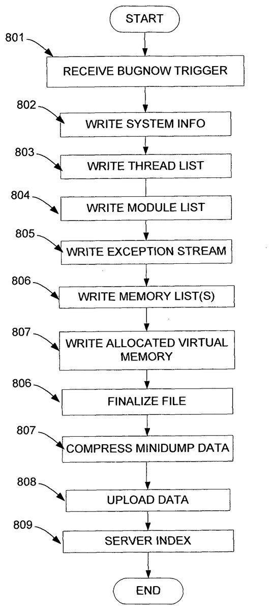
FIG. 8illustrates an example process in which a dynamic debugging dump may be executed. In step801, an input may be received that will trigger the dumping process. For example, in embodiments where a keyboard (or a debugging workstation) is attached to the game console, the game developer may initiate a debugging dump by entering a command line instruction, such as “bugnow .” The command line instruction may include one or more parameters to customize the particular dump. For example, the parameters may include the names of one or more files stored in the game console memory (such as allocated portion708) to be included in the requested debugging dump. The parameters may include one or more data variables to be included in the dump. The parameters may include one or more handles, or names, used to identify one or more predefined groupings of variables, files, memory locations, etc. So, for example, a developer may define in advance (e.g., in core game routine601) a number of different handle values that define a group of files and variables, and including the handle in the command line call will include the predefined group to be included in the debugging dump.
Furthermore, the parameters may include one or more physical memory addresses or address ranges to be included in the dump. These addresses can be the actual physical addresses in the hardware, offset physical addresses, or they may simply be virtual addresses if the game console uses a virtual memory manager to handle non-contiguous allocations and such. Since the game developer might already have an idea as to the source of a problem, the developer might be interested in seeing just the value of one particular variable, or the populated values of one specific physical address or address range in allocated memory705, in the dump. By identifying the specific address(es) in the dump request, the developer may quickly see the most relevant information. For example, the developer may request a dump that contains a specific portion of the game state data705by specifying the address (e.g, physical or logical) of the portion of game state data705storing that specific data.
The parameters may also identify files, variables, and/or addresses that are to be excluded from a requested debugging dump, in much the same way described herein for including such data in a dump. For example, if the developer wants a particular address range, but knows that certain files or variables are not desired, the developer can enter the command with a parameter identifying the desired range and excluding the data that is to be excluded from the dump.
The dump trigger need not be a command line instruction. As an alternative, a dump command may be mapped to a predetermined sequence of inputs made with a game controller104. For example, a sequence of commands involving the buttons132and trigger138(e.g., left trigger+right trigger+start+select+X+Y+A+B buttons) may cause or trigger the debugging dump (crashing the game, if desired). Such a configuration may be particularly useful when the developer is attempting to simulate operation on a production game console in a customer environment, where the customer might only be using a game controller for input (e.g., no testing workstation). This mapping may be done by defining the sequence in the USB host controller230, input recognition routines602, or they may be defined in a game play routine601. The actual definition may take the form of a data list or table.
The dump trigger may be entered dynamically, while the particular game code is running. Additionally, the game code may allow pausing, with an entry of a dump trigger occurring while the game is paused. Furthermore, the game code may use visual and/or audio prompts to the user to guide the user through the process of triggering a dump. For example, a dump option may be displayed on a screen, and a variety of parameters may be displayed for the user's selection. The ability to dynamically request such a dump may be advantageous for catching unanticipated errors, or “soft” errors that are not fatal, such as display errors or errors in non-player character artificial intelligence, or AI. For example, a basketball game might erroneously display the wrong team's mascot at courtside, or one of the computer-controlled players may run out of bounds whenever he/she touches the ball. These kinds of errors are easy to notice in person, but they are difficult to anticipate from a coding perspective, and difficult to account for in advance.
However, for certain errors that can be anticipated (e.g., when a developer includes assertions in the code to test data values during execution, and an assertion fails when a value is not what it is expected to be), a dump may be triggered automatically from within the game program. For example, the game developer may include a “bugnow” command, with any parameters as discussed above, at any location within the game code itself. In this manner, when game play results in execution of a predefined erroneous portion of code, or if the developer includes assertions in the code and an assertion fails, the game console may automatically execute an instruction to trigger a dump. Additionally, if the game console includes an exception handler routine, the game code may register a number of predefined exceptions, such as known possible error states, and may include the “bugnow” dump trigger as part of the exception handling routine for its exceptions. So, for example, an operating system's exception handling may automatically enter a crash state (e.g., a terminal condition in which the game spins idly) upon triggering certain exceptions or failing an assertion. Additionally, or alternatively, a “bugnow” dump trigger may cause the same type of data dump to be prepared and output, but may allow the game program to continue execution as if no error had occurred.
The trigger may also define the information that is to be included in the resulting minidump. This may be done by examining the parameters passed in with the command, or by prompting the user, as discussed above, and may also include consulting predefined data, such as predefined handles for groups of variables or physical address ranges. As an example, this step may include checking the command parameters to identify the actual physical memory addresses (physical addresses may have been passed in as parameters) that are to be included in the dump. In step801, the console may also check to see what data values and/or addresses are to be excluded from the dump. As with the inclusions, these exclusions may be identified as parameters or from other user inputs (e.g., prompt responses). For example, a video game developer might specifically want to exclude texture maps from the dump, as texture maps are unlikely to change during execution. The trigger might instead include an identification of a texture map that was in use when the error occurred, so that the developer can analyze the texture map that was in use when the dump occurred, without taking up memory space and transmission bandwidth for minidump transmission as described herein.
After a dump trigger is received in step801, the game console may proceed with assembling the dump or minidump data that is needed. For example, in step802, the game console may write the system information (e.g., some or all of system information702) into the minidump file or memory location that will be used to form the minidump file (e.g., a memory stream, array or data structure may be instantiated to store pointers to the data that will be in the dump). In steps803and804, the console may write the contents of thread list704and module list703into the minidump file (or memory stream, array, or data structure).
In step805, the console may write an exception stream into the minidump file, containing exception data709.
In step806, the console may write one or more memory listings containing raw contents of memory addresses specified in the parameters. These listing can include the contents of any physical address location(s) specified in the request, such as portions of the game state data (current and/or one or more prior state data705/706) and/or runtime state data (707). The following example application program interface (API) calls can be used to implement these memory listings, where the location and size of the desired address range is obtained and used to obtain the memory listings:
minidump_write_memory_list_stream( )// get game state address and sizegame_state_base_address= game_state_get_buffer_address(&game_state_size);// add game state memory to minidumpminidump_write_memory_block(game_state_base_address, game_state_size,minidump_information, &custom_memory_blocks[custom_memory_block_index]);custom_memory_block_index++;// get runtime state address and sizeruntime_state_base_address=runtime_state_get_buffer_address(&runtime_state_size);// add runtime state memory to minidumpminidump_write_memory_block(runtime_state_base_address, runtime_state_size,minidump_information, &custom_memory_blocks[custom_memory_block_index]);custom_memory_block_index++;// add more memory regions
In the preceding example pseudocode, a memory block array data structure (e.g., custom_memory_blocks) is used to store the minidump being assembled, and the APIs pass pointers to the array location for the data to be added, with ‘custom_memory_block_index’ representing positions in the array. The parameter ‘minidump_information’ may be used to identify characteristic information of a minidump, such as a file handle for the minidump, the size capacity, etc. The ‘game_state_base_address’ parameter may identify a starting physical memory address location, and the ‘game_state_size’ may identify a size of the physical memory address range that is to be added to the dump. Similarly, the ‘runtime_state_base_address’ and ‘runtime_state_size’ parameters may identify an address range to include the runtime state data. The address range could be provided alternatively, such as with a starting and ending address, an ending address and size, an address and one or more offsets, etc. In addition to the game state and runtime state address ranges, the developer can include any number of other memory regions by identifying the desired physical address ranges.
In step807, the allocated virtual memory contents may be added to the minidump. For example, the game console may simply walk through the various memory locations (e.g., pages, blocks, etc.) and include those locations that are in use. The following example pseudocode may be used to perform this step:
minidump_write_virtual_memory_stream( )while (virtual_address virtual_address) &&(next_address <= k_max_virtual_address)){minidump_stream.write_memory_block_to_stream((void *)virtual_address,memory_information.RegionSize);virtual_address= next_address;}}else{virtual_address+= k_page_size;}}
In the preceding example, ‘virtual_address’ and ‘k_max_virtual_address’ are integer values used to create a loop to step through the various memory locations, and at each location, a test is made to determine whether that memory location (or a portion of it) has been allocated or committed, and if it has, then the address for that location is added to the range of addresses that will be used in the memory listing. Each memory region added to the minidump file (or stream, array, etc.) may be preceded in the minidump by header information identifying the size and address location of the region. The ‘memory_information’ data structure includes a state value, which can be a flag to identify whether a particular area in memory is committed, a ‘BaseAddress’ value to identify a starting physical memory address location for a region, and a ‘RegionSize’ value to identify the physical memory size of the region. The ‘next_address’ value may identify the next memory location to check, and may be incremented either by a default value for uncommitted memory (‘k_page_size’) or by the memory region size for a committed region of memory. This approach can be used to obtain contents of virtual memory regions that are of a customized size.
Through this process, contents of virtual memory regions may be added to a data stream, which may be written to a file to form a minidump file. In some situations, the virtual memory regions are all first written to an intermediate data structure, such as an array or data stream, and then when the system has added all the necessary virtual memory regions to the data structure, the system writes the data to an intermediate file, such as a virtual memory stream file (which may exist apart from the minidump file). The contents of this file may then be added, or injected, to the minidump file after the other data (e.g., crash files such as the data described above, screen dumps, crash logs, etc.) have been written to the minidump file. By using this intermediate data structure, the system can reduce hard disk I/O times, and lead to faster minidumps. This arrangement may be faster because a disk access may be needed for each memory region added to a file, and by consolidating the disk accesses some efficiencies may be realized.
In step806, the minidump file may be finalized. Finalization may include copying the minidump's memory stream, array, or other data structure to a file format for transmission, and performing file organization tasks, such as creating a directory and header information for the file to be transported.
In step807, the dump data may be compressed using a lossless data compression algorithm, and in step808, the compressed dump data may be uploaded to a destination. The upload may result in storing the data on the console's memory, storing it on a memory of a test workstation coupled to the console, or uploading it to a network destination, such as an Internet site. If uploading to a network destination, the console may upload the file using secure transmission techniques, such as encryption encoding to help keep the data secure. the file creation and/or uploading may also allow the developer to offer a custom name for the resulting file.
Once the data is uploaded, it may then be analyzed by the developer to isolate a source of a bug. If uploaded onto a network, such as an Internet site, the game developer may use web interface tools to view and analyze the dump's data. In step809, if the data is uploaded onto a network, a network resource (such as a server) may catalog and/or index the dump data for future reference. For example, the dump data may be indexed by time/date, or by the identity of the individual submitting the dump. A unique index, such as a session ID, may be created each time a game is launched, and all data dumped from that session may be associate with this session ID (e.g., file names for separate dumps may include a session ID, dump data may be placed in an electronic folder bearing the session ID, etc.).
The various steps shown inFIG. 8may be implemented using pseudocode such as the following:
long minidump_from_exception(filename,exception_code,exception_information){minidump_write_virtual_memory_stream(memory_stream_file_name);minidump_write_header(&minidump_information);minidump_write_stream_directory(&minidump_information);minidump_write_system_info_stream(&minidump_information);minidump_information.current_stream_index++;minidump_write_thread_list_stream(&minidump_information)minidump_information.current_stream_index++;minidump_write_module_list_stream(&minidump_information);minidump_information.current_stream_index++;minidump_write_exception_stream(&minidump_information);minidump_information.current_stream_index++;minidump_write_misc_info_stream(&minidump_information);minidump_information.current_stream_index++;minidump_write_memory_list_stream(&minidump_information);minidump_information.current_stream_index++;minidump_write_unused_stream(&minidump_information);minidump_information.current_stream_index++;minidump_write_unused_stream(&minidump_information);minidump_information.current_stream_index++;minidump_write_stream_directory(&minidump_information);minidump_finalize_file(&minidump_information);}
The ‘filename’ value is a handle identifying the name of the minidump file, while ‘exception_code’ and ‘exception_information’ are parameters that may be used by an exception handler to identify the type of exception that triggered the dump.
The ‘minidump_write_virtual_memory_stream’ routine receives the name of the memory stream file, and may be used to instantiate the file that will be used to store the virtual memory stream.
The ‘minidump_write_header’ routine receives a pointer to the minidump_information data structure, and is used to add header information for the minidump file. The header information can identify characteristics of the file, such as size, and may be added directly to the file or may be added to an intermediate data structure (e.g., a data stream, array, etc.) for subsequent adding to a file.
The ‘minidump_write_stream_directory’ routine may add a directory to the minidump file so that it's contents may be easily retrieved. The remaining routines may be used to write the data as indicated in their names. The ‘minidump_write_unused_stream’ routine may be used to write one or more unused data streams to the minidump file, and may serve as placeholders should the system need to inject additional data into the minidump (e.g., if the system wishes to edit the file without changing its characteristics, such as its size or location, the system can simply replace some or all of the unused streams in the minidump file. In some cases, writing multiple unused streams to the minidump file, to create additional available space for such future expansion, may be desirable.
In the preceding example, the minidump may be a memory array data structure indexed by an integer value ‘minidump_information.current_stream_index,’ and the overall process may be provided with parameter data identifying the minidump file name and the libraries and/or locations of the various routines to be called. Additionally, the various routines may be used to combine multiple existing memory I/O streams into a single stream, simplifying and streamlining the system.
The features described above are preferably encoded in computer software as executable instructions that can be executed on a computing device, such as a personal computer or video game console, to result in the display of the screens shown in the figures. The executable instructions may be stored on a computer-readable medium, such as one or more computer disks, RAMs, CD-ROMs, DVDs, game cartridges, etc. Also, although various features are described above, it is not necessary to practice them all in the same embodiment. Instead, various combinations and subcombinations may be implemented as desired, and the true scope of the present invention should only be limited by the claims that follow.
Although the subject matter has been described in language specific to structural features and/or methodological acts, it is to be understood that the subject matter defined in the appended claims is not necessarily limited to the specific features or acts described above. Rather, the specific features and acts described above are disclosed as example forms of implementing the claims.
Claims
- A computer program testing method, comprising: launching a game program for testing on a game console, the game console being a dedicated computing device configured for home entertainment, wherein the game console omits a printer communication port and the game console omits an internal hardware expansion slot;responsive to the launching, the game console creating a unique session identifier (ID) for the game program;executing the game program on the game console, the executing game program being associated with the unique session ID;detecting an error in the game program that is executing;responsive to detecting the error in the game program that is executing, receiving, from a device connected to the game console, an indication to activate a debugging dump trigger command, wherein the debugging dump trigger command includes an identification of a physical game console memory address range whose data is to be included in a requested data dump and a requested dump destination;in response to receipt of the debugging dump trigger command: collecting data from the physical game console memory address range;and transmitting the collected data to the requested dump destination;and indexing the collected data at the dump destination, wherein the indexing is based at least on the unique session ID with which the collected data are associated.
- The computer program testing method of claim 1 , wherein the debugging dump trigger command results in execution of an instruction within the game program executing on the game console.
- The computer program testing method of claim 1 , wherein the game program automatically sends a minidump of information as defined by the debugging dump trigger command to a server.
- The computer program testing method of claim 3 , wherein the debugging dump trigger command is activated automatically by the game program using an exception handler.
- The computer program testing method of claim 1 , wherein said transmitted data includes: game program build version information;and information identifying a user using said game console.
- The computer program testing method of claim 1 , further comprising receiving an indication of data that is to be excluded from the requested dump, wherein the indication of data that is to be excluded from said requested dump includes parameters identifying files, variables and one or more addresses that are to be excluded from the requested data dump.
- The computer program testing method of claim 1 , wherein the dump destination comprises an Internet server.
- The computer program testing method of claim 7 , wherein the transmitting employs encrypted transmission, and wherein the collected data is compressed before transmission.
- The computer program testing method of claim 1 , wherein the debugging dump trigger command is received during a first game state, and the transmitting further includes transmitting game state data for at least one game state occurring prior to the first game state.
- The computer program testing method of claim 1 , wherein the transmitted data includes game console hardware identification information.
- The computer program testing method of claim 1 , wherein the requested dump destination includes at least one destination and the data dump is performed by a routine corresponding to a respective destination;the respective destination including one of: an on-screen destination, wherein the dump causes data to be displayed on a screen by an output controller routine;a memory destination, wherein the dump causes data to be written to a memory as one or more files by a memory controller routine;or a network destination, wherein the dump causes data to be uploaded to a network destination by a network interface routine.
- The computer program testing method of claim 11 , wherein the routine is incorporated in the game console separate from the game program.
- The computer program testing method of claim 11 , wherein the routine is incorporated in the game program.
- The computer program testing method of claim 1 , the device connected to the game console including a game controller, and the debugging dump trigger command including a predetermined sequence of inputs made with the game controller.
- One or more computer-readable storage media excluding signals per se, the computer-readable storage media storing computer-executable instructions that, upon execution cause a game console to perform a test of a game program by performing operations comprising: launching the game program to test on the game console, the game console being a dedicated computing device configured for home entertainment, wherein the game console omits a printer communication port and the game console omits an internal hardware expansion slot;responsive to the launching, the game console creating a unique session ID for the game program;executing the game program on the game console, the executing game program being associated with the unique session ID;detecting an error in the game program that is executing;responsive to detecting the error in the game program that is executing, receiving a debugging dump trigger command, wherein the debugging dump trigger command includes an identification of a physical game console memory address range whose data is to be included in a requested data dump and a requested dump destination;in response to receipt of the debugging dump trigger command;collecting data from the physical address range;and transmitting the collected data to the requested dump destination for indexing based at least on the unique session ID with which the collected data are associated.
- The one or more computer-readable storage media excluding signals per se as recited in claim 15 , wherein the authenticated dedicated computing device for home entertainment is authenticated to form games amongst multiple players or to purchase services from online services via a distributed service ticket.
- A game testing system comprising: a game controller;and a game console, the game console being a dedicated computing device configured for home entertainment, wherein the game console omits a printer communication port and the game console omits an internal hardware expansion slot, the game console configured to perform game test operations comprising: launching a test of a game program on the game console;responsive to the launching, the game console creating a unique session ID for the test of the game program;associating the unique session ID with the test of the game program;executing the game program on the game console, the executing game program being associated with the unique session ID;detecting an error in the game program that is executing;responsive to detecting the error in the game program that is executing, receiving an indication to activate a debugging dump trigger command that includes an identification of a physical game console memory address range whose data is to be included in a requested data dump and a requested dump destination;in response to receipt of the debugging dump trigger command: collecting data from the physical game console memory address range;and transmitting the collected data to the requested dump destination;and indexing the collected data at the dump destination according to the unique session ID with which the collected data are associated.
- The game testing system of claim 17 , the game test operations further comprising: responsive to detecting the error in the game program that is executing: identifying an error condition in a first process of the game program that is executing on the game console;issuing, from the first process as part of the debugging dump trigger command, a first call to a physical memory list error data dumping process, said first call including: a first parameter identifying the physical game console memory address range, a second parameter identifying an error data dump structure, and a third parameter identifying a location in said error data dump structure, the location based at least on the unique session ID;and the physical memory list error data dumping process retrieving memory contents from the physical game console memory address range, and adding the retrieved memory contents to the error data dump structure at the identified location.
- The of gaming testing system claim 18 , the game test operations further comprising at least one of: issuing, from the first process, a second call to the physical memory list error data dumping process to add contents of a second physical game console memory address range to the error data dump structure;or issuing a call to a virtual memory error data dumping process, the virtual memory error data dumping process sequentially checking portions of a memory for whether the portions are allocated, and adding the allocated portions to the error data dump structure.
- The game testing system of claim 18 , wherein the third parameter identifying the location in the error data dump structure comprises passing a pointer to the location for adding the memory contents.
Disclaimer: Data collected from the USPTO and may be malformed, incomplete, and/or otherwise inaccurate.