U.S. Pat. No. 8,083,589
CAPTURE AND UTILIZATION OF REAL-WORLD DATA FOR USE IN GAMING SYSTEMS SUCH AS VIDEO GAMES
AssigneeReference, LLC
Issue DateApril 15, 2005
Illustrative Figure
Abstract
A portable sensor unit for capturing motion and/or other data may be securely mounted on objects such as a user's limb, a vehicle, or other items. The sensor unit may then collect motion and/or other data from the object to which it is affixed, and may provide this data to a data logger which stores the data. The data logger may subsequently communicate the data to a gaming system which may tailor the motion characteristics of a virtual object to resemble those of the real-world object from which the motion data was captured. Thus, a user can (for example) capture motion data from a vehicle, with this data being supplied to a video gaming unit which provides a virtual vehicle having the same acceleration/deceleration, handling, and other characteristics.
Description
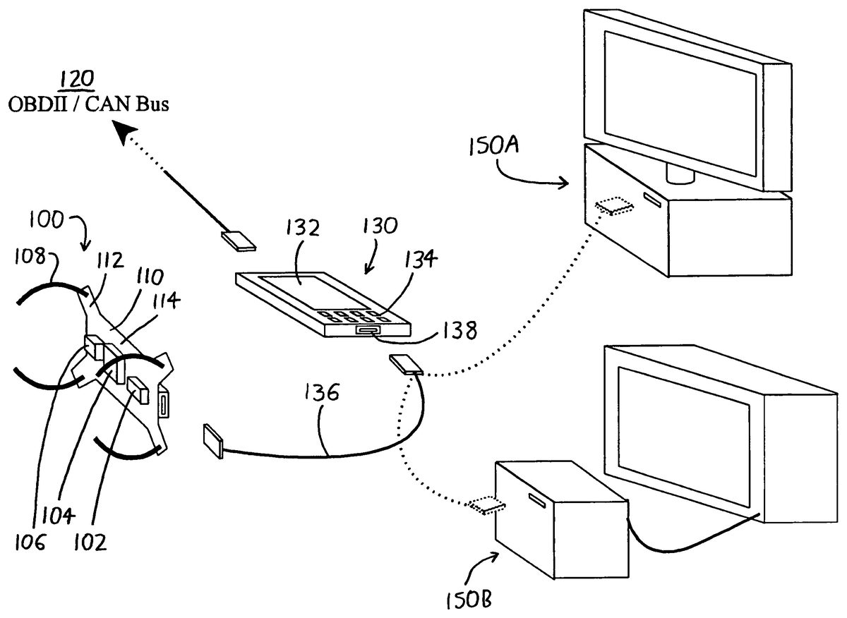
DETAILED DESCRIPTION OF PREFERRED VERSIONS OF THE INVENTION To elaborate on the description given in the foregoing Summary section of this document,FIG. 1illustrates an exemplary simplified version of the invention wherein the sensor unit100collects motion data by use of one or more sensors, here an accelerometer102, a gyroscope104, and a GPS unit106. The sensor unit100may be attached to an object via mounting means (such as straps108), may be activated, and may then collect data reflecting the motion of the attached object. The captured motion data is supplied to and stored in a data logger130, which subsequently supplies the motion data to a gaming unit150. The gaming unit150then utilizes the motion data to define the motion characteristics of virtual objects in a game so that the virtual objects better simulate the behavior of the real-world objects from which the motion data was captured. It is particularly beneficial that the sensor unit100be configured for rapid, easy and firm mounting to a wide variety of different objects, andFIG. 1depicts the sensor unit100as having a generally flat/planar configuration with an irregular circumference from which mounting legs112extend. The mounting means (straps108) preferably extend from the mounting legs112to allow easy attachment of the sensor unit100about (for example) a limb, an article of sporting goods (e.g., a baseball bat), a portion of a vehicle (e.g., a car armrest), etc. It should be understood that the straps108are shown in greatly simplified form inFIG. 1, and they need not take the form of simple tie cords, but could instead be loops, hooks, or other structures for wholly or partially encircling an object, and could bear buckles, snaps, hoop-and-loop fastener, or other means for releasably fastening the straps108. Further, as will be discussed below, the mounting means can take a wide variety of other forms, e.g., fasteners (such as snaps ...
DETAILED DESCRIPTION OF PREFERRED VERSIONS OF THE INVENTION
To elaborate on the description given in the foregoing Summary section of this document,FIG. 1illustrates an exemplary simplified version of the invention wherein the sensor unit100collects motion data by use of one or more sensors, here an accelerometer102, a gyroscope104, and a GPS unit106. The sensor unit100may be attached to an object via mounting means (such as straps108), may be activated, and may then collect data reflecting the motion of the attached object. The captured motion data is supplied to and stored in a data logger130, which subsequently supplies the motion data to a gaming unit150. The gaming unit150then utilizes the motion data to define the motion characteristics of virtual objects in a game so that the virtual objects better simulate the behavior of the real-world objects from which the motion data was captured.
It is particularly beneficial that the sensor unit100be configured for rapid, easy and firm mounting to a wide variety of different objects, andFIG. 1depicts the sensor unit100as having a generally flat/planar configuration with an irregular circumference from which mounting legs112extend. The mounting means (straps108) preferably extend from the mounting legs112to allow easy attachment of the sensor unit100about (for example) a limb, an article of sporting goods (e.g., a baseball bat), a portion of a vehicle (e.g., a car armrest), etc. It should be understood that the straps108are shown in greatly simplified form inFIG. 1, and they need not take the form of simple tie cords, but could instead be loops, hooks, or other structures for wholly or partially encircling an object, and could bear buckles, snaps, hoop-and-loop fastener, or other means for releasably fastening the straps108. Further, as will be discussed below, the mounting means can take a wide variety of other forms, e.g., fasteners (such as snaps or other male/female connectors extending from the mounting legs112, or fasteners such as bolts extending through the mounting legs112), adhesive pads (including adhesive tape, hook and loop fastener, magnets, suction cups, etc.), pockets/pouches or other receptacles for receiving all or a portion of the sensor unit100, and so forth.
Also, for ease of attachment, portability, and minimal encumbrance, it is preferable that the sensor unit100be small and lightweight. Particularly preferred versions for attachment about a user's limb of the like measure approximately 2 inches wide by 4 inches long by 1 inch high, but much of this area is unused space on the mount body110, which could be made much smaller. In any event, it is preferred that the sensor unit100not exceed 8 inches in any dimension, since such a size begins to pose difficulties for portability, versatile usage, and ease of attachment.
The sensors included on the sensor unit100can vary, but for most gaming applications, it is believed that an accelerometer102can allow capture of most data of interest (which is primarily motion data). A 3-axis accelerometer, which measures acceleration in three orthogonal directions, is particularly preferred. Accelerometer data can be integrated to obtain velocity and position data, and vector calculations can allow quantification of translational motion (acceleration, velocity, position) in any direction on or off of the axes. Motion data in further degrees of freedom can be obtained by including the gyroscope104, and most preferably a 3-axis gyroscope, whereby angular acceleration/velocity/position can be measured. The GPS unit106, which is optional, is also useful for measuring bulk or “coarse” distance/position data, particularly since distance/position data generated solely by integrating accelerometer data can accumulate error over time. Thus, more accurate distance/position readings can be developed (particularly over larger distances) by utilizing the data from the GPS unit106, either alone or in combination with distance data integrated from the accelerometer102. Other useful sensors are tensionometers, which (when mounted on a limb or another part of the body) can help to measure strength and endurance; shock sensors, which can help measure punching/kicking strength and speed, as well as reflex actions; and pressure sensors, which can measure muscle activity when mounted on or in close proximity to a muscle (as by strapping the sensor unit100about the user's arm or leg with a pressure sensor resting atop a muscle group).
It should be understood that the gyroscope104, GPS unit106, and/or other sensors need not be provided onboard the sensor unit100(as depicted inFIG. 1), and these could instead be provided as separate item which plug into appropriate ports in the sensor unit100when their use is desired. Alternatively, they could be provided as separate items which communicate directly with the data logger130, in which case the sensor unit100might bear some type of attachment means, either on its lower surface114or its upper surface (not shown inFIG. 1), for attaching the additional sensors to the sensor unit100and allowing them to be carried on the sensor unit100with the accelerometer102. In this manner, all data measurements can still be taken from approximately the same location (if desired) when the sensor unit100is attached to the object of interest from which measurements are to be taken. In this respect, it is notable that the system need not collect data from one location/object at a time, and it could possibly use multiple sensor units100at different locations, and/or could use one or more sensor units100in combination with other data sources. As an example, if the data logger130has multiple data communication channels, it might collect data from a sensor unit100mounted on a user's limb, and could simultaneously collect data from some other sensor at another location (e.g., from a resistance meter attached to a bicycle on which the user is riding). In this respect, where data is to be collected from an automobile or similar motor vehicle, it is particularly useful to receive and store data from an automotive system diagnostic port120, e.g., an Onboard Diagnostics II (OBDII) or Controller Area Network (CAN) bus port. Such ports120can provide data directly from automotive sensors, and thus provide data related to parameters such as vehicle speed, motor rpm, coolant/oil temperatures, torque/horsepower, brake activity, steering angle input, stability management information, gear selection, tire pressure, ambient temperature/pressure, and even vehicle identification data (such as the vehicle identification number). In the version of the invention depicted inFIG. 1, the data from the automotive systems diagnostic port120is connected directly to the data logger130, and thus the data logger130collects and stores data from the diagnostics port120as well as from the sensor unit100. However, similarly to the alternatives discussed above, the sensor unit100could itself include a cable or other connection to the automotive systems diagnostics port120.
It is also possible to have at least some of the data used by the gaming unit collected solely by the data logger130, assuming the data logger130has the capability to independently collect data inputs. As an example, if the data logger130is a personal computer or PDA, it could provide a questionnaire asking the user to (for example) rank the difficulty of some task that was just prompted/requested by the data logger130, or rank fatigue, hunger, etc. As another example, the data logger130could collect data relating to matters such as mental acuity and/or intelligence, as by presenting a quiz to the user, either by itself or during some type of physical activity regimen from which the sensor unit100will collect data.
The data logger130may take the form of any device which is capable of storing data, and particularly preferred forms of data loggers130are handheld personal computers and PDAs, which tend to include features such as display screens132for illustrating input prompts and output to users, input means134(e.g., keyboards/touch screens), and USB (Universal Serial Bus) or other types of standard connection ports138for receiving and/or sending data (though data communication might additionally or alternatively occur wirelessly). The benefit of such data loggers130is that they are readily available and relatively inexpensive, and applications for collecting and labeling data can be readily created for and downloaded onto such data loggers130. In suitable environments, the data logger can simply be a laptop computer (useful, for example, on an unoccupied car seat where the sensor unit100is being used to collect vehicle performance data), or a standard personal computer (useful, for example, where performance data is being collected from a user who is exercising indoors, e.g., on a treadmill, weightlifting bench, exercise mat, etc.).
While the data logger130could take the form of little more than a device which continuously or periodically writes the sampled data to a memory without any processing beforehand, it is useful if the data logger130has some degree of programmability. Programmability allows for more “intelligent” data collection, for example, allowing data collection to start and/or stop upon some predetermined event, allowing different data to be collected at desired times, etc. To illustrate, when taking endurance measurements, the data logger130could be programmed to detect a 0.2 G acceleration detected at the sensor unit100as a triggering event, and could then measure the time during which a substantially constant velocity is maintained.
Additionally, since many sensors provide data outputs which do not directly reflect real-world units of measurement (i.e., sensor outputs are often in counts or voltages which require interpretation in order to be converted into useful parameters/measurements), the data need not be stored in the data logger130or delivered to the gaming unit150in a “raw” or as-collected form. As an example, the data logger130may perform data formatting or other conversion prior to data storage (e.g., it might “condense” the data by creating representative data values, equations, or coefficients which statistically or otherwise represent the data). It is also or alternatively possible that the data logger130could simply store raw data obtained from the sensor unit100, and the gaming unit150could then perform its own data conversion before using the data. However, it is preferred that the sensor unit100and/or data logger130organize and process the data prior to providing it to the gaming unit150, so that the gaming unit150simply receives the lookup tables, equations, coefficients, or other values necessary to drive its physics engine to simulate the real-world object from which the data was collected.
InFIG. 1, data transmission between the sensor unit100and the data logger130is illustrated as occurring via a cable136. However, it should be understood that data communication could also or alternatively occur by physical relocation of memory media between the sensor unit100and the data logger130(e.g., swapping a memory card between the sensor unit100and the data logger130), by wireless communication, or by other modes of communication.
To illustrate an exemplary process for collection of data, following is a possible routine that might occur during data collection from a vehicle. Upon connection of the data logger130to the sensor unit100(which might be affixed to the vehicle's dashboard), the data logger130might display a prompt such as “Collecting data: 0-60 acceleration. Press start to begin.” The user could then press the “Start” button displayed on the touch screen132(or could press an appropriate key on the keyboard134), and could then press the accelerator pedal. Data collection might start once the “Start” button is depressed, or for greater accuracy, it might not begin until the sensor unit100detects that motion has begun. Once 60 mph is reached, the user could then press a “stop” button and data collection can cease (unless it ceased beforehand, e.g., upon detection of 60 mph speed by the sensor unit100and data logger130. The data logger130might then display “Deceleration: 60-0 braking. Press start to begin.” The user could then press “Start,” execute the indicated action, and press “Stop” when finished. Another prompt might then be displayed, such as “Handling: execute right turn at approximate 5 mph speed. Press start to begin,” and the user can again proceed to collect data. In this manner, the sensor unit100and data logger130establish a data set characterizing the motion characteristics of the vehicle: its acceleration, braking, handling, etc.
The data set can then be provided to the gaming system150, and to a game which is configured to accommodate the data set and apply it to its “physics engine” (i.e., the rules/algorithms governing motion) so that the motion of virtual objects within the game will more accurately simulate those of the real-world objects. As an example, if the game in the gaming unit150relates to a racing game/simulation, the gaming unit150might allow the user to download some or all of the collected data from the data logger130. Alternatively, the data logger130could do no more than simply display data values (or representative coefficients, etc.) on its display screen132, and the user could then type in or otherwise enter these values into a gaming unit150. The gaming unit150would then provide a car (or other vehicle) in the racing game with acceleration, braking, steering, etc. responses resembling those measured by the sensor unit100from the real-world vehicle.
FIG. 2then provides a view of a prototypical sensor unit200, wherein the accelerometer and/or other sensors are situated within the casing or mount body210of the sensor unit200. Several mounting legs212extend from the circumference of the mount body210, with the mounting legs212here being defined as a series of tubular members which protrude from both the circumference of the mount body210, and also from the planes of its outer surface216and inner surface (not shown). The sensor unit200can be directly affixed to an object, as by inserting fasteners through the mounting legs212and into an object; extending straps/attachment cords through or about the legs212, and subsequently about the object; or by other mounting means.FIG. 2illustrates several mounting means provided in the form of intermediate mounting structures, such as the attachment bracket260. The attachment bracket260has a base262adapted to affix to other structure, e.g., to the “island” of a vehicle (the area between the front seats), and the legs212of the sensor unit200may be attached to an upwardly-extending flange264via fasteners and the like. The sensor unit200may communicate with the data logger250wirelessly or via its cable236(which terminates in a conventional USB connector238, and which is not necessarily shown to scale inFIG. 2). The data logger250could rest at any convenient area adjacent the attachment bracket260, e.g., on an adjacent vehicle seat so that a driver/user can follow prompts presented by the data logger250, can initiate data collection, etc.
Alternatively, a user might fit the sensor unit200into the pouch270, which bears a clip272for affixing the pouch270onto (for example) an article of clothing worn by the user. As an illustration, a user might affix the pouch270to a belt or waistband to which the data logger250might be separately clipped. The user could then run, ride a bicycle, or engage or in other activities from which data can be collected.
The wrap280is intended to allow the sensor unit100to fit about an object such as the user's limb, some portion of a vehicle, some article of sporting goods, etc. Here, the sensor unit100may be fit against the plate282with its mounting legs212aligned to receive the protruding pins288, and with the retaining band284then firmly holding the sensor unit200onto the plate282. The strap286can then be wrapped about the user's limb or another object, and may have its opposing ends affixed together by buckles, hook-and-loop fastener, or the like, and the sensor unit200may then collect data from the object as it moves. In this case, the cable236might extend to the user's waist, where the data logger250might be clipped.
It is notable that while mounting means (such as fasteners, straps, or other matter) could be provided on various different regions of the sensor unit100, it has been found to be particularly useful to provide the mounting means on the protruding legs212. Mounting means extending from the legs212provide a secure multipoint connection to an object, which is useful since single-point attachments (as from a mounting “stem”), and/or simple dual point attachments, are susceptible to spurious vibration of the sensor unit100in one or more planes. Additionally, the protruding legs212are also useful because they present an irregular profile which is easily fit into certain types of mounting means (such as the pouch270or the wrap280), and which is firmly grasped by such mounting means even if the portion of the user or object to which the sensor unit200is mounted is undergoing extremely vigorous motion.
FIG. 3illustrates a sensor unit300which is a variation of the sensor unit200ofFIG. 2. The sensor unit300has generally the same configuration as the sensor unit200, with a mount body110having generally the same size/shape (and generally the same mounting legs312, etc.), but here the sensor unit300incorporates the data logger within its mount body310. A display screen332and input means334(input/output buttons) are provided to allow the user to easily enable and disable data collection. A USB or other data communication port (not shown) may be included on the mount body310to allow communication of data to a gaming unit, or alternatively such communications could occur wirelessly or by physical transfer or memory media (e.g., by swapping a memory card).
Various exemplary versions of the invention have been shown and described to illustrate possible features of the invention, but modifications are also considered to be within the scope of the invention. In particular, as illustrated by the sensor unit300(with data logger incorporated therein), it is possible to combine and/or separate various components of the invention. As previously noted, the sensor unit and data logger can be combined, or the data logger and the gaming unit could be combined as well (e.g., where a personal computer is used as both the gaming unit and a data logger). It is also possible to incorporate all of the sensor unit, data logger, and gaming unit in a single device, for example, into a portable gaming unit. In this example, a user could mount the gaming unit to the user's body, a vehicle, or another object, and the gaming unit might provide prompts to the user to initiate data collection runs. Upon collecting the data, the gaming unit could then utilize collected data in subsequent game play. One disadvantage with this approach is that many portable gaming units are not constructed with the desired degree of durability for the sensor unit (which is preferably somewhat rugged). However, some cell phones/portable telecommunications devices are ruggedly constructed, and these devices may be good candidates for incorporation of a sensor unit, data logger, and gaming unit. Since such devices are often designed to be carried by or attached to users, such devices are also good candidates for incorporation of a sensor unit and data logger for collection of motion data from the user, to later be transmitted—perhaps via wireless internet—to a gaming unit. In this instance (as well as with the other versions of the sensor units discussed above), the data collected from the user's activities might have utility to medical personnel, physical therapists, and the like, apart from use in the gaming unit, because the sensor unit promotes a particularly convenient means for collecting and transmitting physiological data.
Similarly, it is notable that while the invention has benefits for recreational gaming, other uses—e.g., in educational training and simulation activities—can also be particularly valuable. The system allows a user to execute health, physical education, and science simulations which accurately resemble real-world conditions, but which would be too expensive or dangerous to actually run under real-world conditions. Regarding the physical education setting, video and computer games are often blamed for disinterest in physical activity, but if a user's gaming performance is linked to the user's actual physical abilities, the user has an incentive to develop physical fitness in order to enhance game play.
The invention is not intended to be limited to the preferred versions of the invention described above, but rather is intended to be limited only by the claims set out below. Thus, the invention encompasses all different versions that fall literally or equivalently within the scope of these claims.
Claims
- A data capture and utilization system comprising: a. a portable sensor unit including: (1) an accelerometer capable of detecting motion in at least one dimension, (2) mounting means for removably affixing the sensor unit to an object, and (3) a display screen, (4) a data logger connected in communication with the accelerometer and storing data supplied therefrom during a data capture time period, wherein: (a) the data capture time period follows an instruction delivery period wherein instructions are delivered on the display screen regarding how the object should be moved with the sensor unit mounted thereon, and (b) the stored data includes multiple data entries supplied from the accelerometer during motion of the object in accordance with the delivered instructions, the multiple data entries being spaced in time over the data capture time period;wherein the sensor unit is sized and configured to be hand-held or smaller;b. a gaming unit connectable in communication with the data logger, the gaming unit: (i) not being connected in communication with the data logger during the data capture time period, and (ii) being connected in communication with the data logger following a delay period after the data capture time period, wherein no data storage by the data logger occurs over the delay period, the gaming unit being configured to: (1) receive data previously stored in the data logger over the data capture time period, (2) provide a game wherein a virtual object is displayed in motion, wherein the motion of the virtual object is: (a) independent of any data acquired by the sensor unit outside of the data capture time period, and (b) dependent on: i. the data received by the gaming unit from the data logger, and ii data collected from a game player during the display of the moving virtual object.
- The system of claim 1 wherein: a. the data logger is physically connected to the sensor unit, and b. the data logger includes: (1) input means for inputting data and/or instructions, (2) an internal processor providing output on the display screen in response to data and/or instructions input to the input means.
- The system of claim 1 wherein the sensor unit includes: a. a mount body whereupon the accelerometer is situated;b. multiple mounting legs extending from the mount body, wherein the mounting means is provided on the mounting legs;and wherein the mounting means is situated in a plane spaced away from the accelerometer, whereby the accelerometer is situated spaced from any object whereupon the mounting means is affixed.
- The system of claim 3 wherein the mount body has: a. an upper side facing away from the plane in which the mounting means rests, b. a lower side facing toward the plane in which the mounting means rests, wherein the accelerometer is situated on the lower side.
- The system of claim 1 wherein the data logger is also removably connected in communication with the system diagnostics port of an automobile.
- The system of claim 1 further comprising a gyroscope situated on the sensor unit, wherein the data logger is also in communication with the gyroscope.
- The system of claim 4 wherein the mounting means is situated on the mounting legs to extend therefrom in a direction oriented away from the lower side.
- The system of claim 1 wherein: a. the data received by the gaming unit from the data logger defines motion characteristics of the virtual object, and b. the data collected from a game player defines the motion of the virtual object, such motion being in accordance with the defined motion characteristics.
- The system of claim 8 wherein the data collected from a game player during the display of the moving virtual object is not accelerometer data from the portable sensor unit.
- A data capture and utilization system comprising a portable sensor unit which includes: a. a mount having a mount body with multiple mounting legs extending therefrom, wherein the mount is sized and configured to be portable, with a size of no greater than 8 inches at most in any dimension, b. at least one accelerometer affixed to the mount body, each accelerometer being capable of detecting motion in at least one dimension;c. a mounting means situated on each mounting leg for affixing the mounting leg to an object, with the mounting means being capable of maintaining the mount in affixment with a vertical surface;d. a display screen configured to deliver instructions, wherein the instructions direct how the object should be moved;and e. a data logger in communication with the accelerometer to store data supplied therefrom, the stored data not being communicated elsewhere until: (1) a data set has been stored in the data logger, the data set containing accelerometer data over a desired data capture time period following delivery of the instructions on the display screen;and (2) a delay period has elapsed: i. which is greater than the data capture time period, and ii. during which no accelerometer data is stored in the data logger.
- The system of claim 10 further comprising a gaming unit connectable to the data logger, the gaming unit: A. not being connected in communication with the data logger during the data logger's storage of accelerometer data, and B. being connected in communication with the data logger thereafter, after a delay period has elapsed wherein no data storage by the data logger has occurred, the gaming unit: a. receiving the data set previously stored in the data logger, b. providing a game wherein a virtual object is displayed in motion, and c. altering the characteristics of the motion of the virtual object during the game: (1) in dependence on: i. the data set received from the data logger, and ii. data collected from a game player during the game, (2) without regard to any accelerometer data acquired during the game.
- The system of claim 10 wherein: a. the mounting body has a surrounding circumference from which the mounting legs extend, and b. the mounting means are situated on the mounting legs in a plane spaced from the mounting body.
- The system of claim 12 wherein a. the mounting body has a lower surface from which the legs extend and an opposing upper surface, whereby the lower surface is closer to the mounting means than the upper surface, and b. the accelerometer is affixed to the lower surface.
- The system of claim 10 wherein: a. a data port is situated on the mount, and communicates data between the accelerometer and data logger;and b. the data logger is defined by a portable handheld device which is removably connectable to the data port.
- The system of claim 10 further comprising connection means for connecting to the system diagnostics port of an automobile.
- The system of claim 10 further comprising a gyroscope also connected in communication with the data logger.
- A method for capturing and utilizing data comprising the steps of: a. providing a portable sensor unit including: (1) an accelerometer capable of detecting motion in at least one dimension, (2) a data logger in communication with the accelerometer to store data supplied therefrom, (3) a display screen, and (4) mounting means for removably affixing the sensor unit to an object;b. mounting the sensor unit to an object;c. delivering instructions on the display screen as to how the object should be moved;d. storing data from the accelerometer in the data logger over a desired data capture time period during motion of the object in accordance with the instructions, the stored data being in a data set;e. after a delay period has elapsed which is at least as great as the data capture time period, subsequently providing the data set from the data logger to a gaming unit, wherein: (1) the gaming unit provides a game wherein virtual objects are displayed in motion, with such motion being dependent on: i. the data set received from the data logger, and ii. data received by the gaming unit during the display of the moving virtual objects, and (2) the gaming unit does not: i. receive data from the accelerometer or data logger during the data logger's storage of the data set, or ii. make use of any data collected during the game by the sensor unit.
- The method of claim 17 wherein the portable sensor unit further includes: a. input means for inputting data and/or instructions, b. an internal processor providing output on the display screen in response to data and/or instructions input to the input means.
- The method of claim 17 further comprising the steps of: a. delivering sets of instructions on the display screen as to how the object should be moved, the sets of instructions being delivered periodically over time;b. storing motion data sets from the accelerometer in the data logger, wherein each motion data set corresponds to one of the sets of instructions;c. after two or more motion data sets are stored, providing the stored sets to a gaming unit.
- The method of claim 17 : a. wherein the moving object is an automobile;b. further comprising the step of also storing data from a system diagnostics port of the automobile in the data logger during motion of the automobile.
- The method of claim 17 further comprising the step of ceasing the motion of the object before providing the stored data to the gaming unit.
- The method of claim 21 further comprising the step of removing at least the data logger of the sensor unit from the object before providing the stored data to the gaming unit.
- The method of claim 17 wherein: a. the data set received by the gaming unit from the data logger defines motion characteristics of the virtual objects, and b. the data received by the gaming unit during the display of the moving virtual objects defines the motion of the virtual objects, such motion being in accordance with the defined motion characteristics.
- The method of claim 17 wherein the data received by the gaming unit during the display of the moving virtual objects is not accelerometer data from the portable sensor unit.
- A data capture and utilization system comprising: a. a portable sensor unit including: (1) an accelerometer capable of detecting motion in at least one dimension, the portable sensor unit being removably provided on a moving real-world object, and (2) a display screen configured to deliver instructions to a user regarding the user's motion of the real-world object;(3) a data logger in communication with the accelerometer, wherein the data logger stores a motion data set supplied from the accelerometer over a data capture period following the delivery of the instructions, the motion data set containing multiple data entries spaced in time over the data capture period which are representative of the user's motion of the real-world object in accordance with the instructions;b. a unit connectable in communication with the data logger, wherein after the data capture period has elapsed, the unit later: (1) receives the motion data set from the data logger, (2) processes the motion data set, (3) generates a simulation wherein the motion of a virtual object is modeled, and (4) alters the characteristics of the motion of the virtual object in dependence on: i. the motion data set, and ii. data received from a user during the modeling of the motion of the virtual object, without regard to any concurrent motion of the portable sensor unit.
- The system of claim 25 wherein the sensor unit includes: a. a mount body;b. mounting legs extending from opposing sides of the mount body, c. a mounting means situated on each of the mounting legs for affixing each mounting leg to the real-world object, wherein the accelerometer is situated on the mount body such that it is situated in a plane spaced from the mounting means on the mounting legs, and spaced from the real-world object to which each mounting leg is affixed.
- The system of claim 25 wherein the motion data set defines the responsiveness of the motion of the virtual object to the data received from the user.
- The system of claim 25 wherein the data received from a user during the modeling of the motion of the virtual object is not accelerometer data from the portable sensor unit.
- A method for capturing and utilizing data including the following steps performed by a user: a. removably providing a portable sensor unit on a moving real-world object, the portable sensor unit including: (1) an accelerometer capable of detecting motion in at least one dimension, (2) a display screen, and (3) a data logger;b. storing a motion data set from the accelerometer within the data logger during a data capture period over which motion of the real-world object occurs, wherein the motion data set: (1) is representative of the user's motion of the real-world object in accordance with instructions provided on the display screen, and (2) contains multiple data entries spaced in time over the data capture period;c. after the data capture period and a delay period thereafter which is at least as great as the data capture period, providing the stored motion data set to a simulation unit separate from the portable sensor unit;d. generating a simulation within the simulation unit wherein the motion of a virtual object is modeled, and wherein the motion of the virtual object is: (1) dependent on: i. the stored motion data set, and ii. data received during the modeling of the motion of the virtual object, and (2) independent of any motion of the sensor unit occurring during the simulation.
- The method of claim 29 wherein the motion of the virtual object is also dependent on data collected from the system diagnostics port of an automobile.
- The method of claim 29 wherein the virtual object has a motion response resulting from the data received during the modeling of the motion of the virtual object, with the virtual object's motion response at least partially simulating a motion response of the real-world object to a motion command, the motion response of the real-world object being defined by the stored motion data set.
- The method of claim 29 wherein the data received during the modeling of the motion of the virtual object is not accelerometer data from the portable sensor unit.
Disclaimer: Data collected from the USPTO and may be malformed, incomplete, and/or otherwise inaccurate.