U.S. Pat. No. 8,065,965
PORTABLE VIDEO GAME TABLE
Issue DateApril 10, 2009
Illustrative Figure
Abstract
A portable video game table comprising: a table surface with an underside; at least one spring-loaded floor leg rotatably attached to the underside; at least one spring-loaded sofa leg rotatably attached to the underside; a floor leg locking mechanism located on the at least one spring-loaded floor leg; a sofa leg locking mechanism located on the at least one spring-loaded sofa leg; where the table is configured such that the portable video game table can change to and from a folded configuration and a ready-for-use extended configuration.
Description
DETAILED DESCRIPTION FIG. 1shows a perspective view of one embodiment of the disclosed portable video game table10. The disclosed portable video game table can be used with video games, portable games (e.g. Gameboy), computer games, laptop computers, and other electronic devices. A table surface14has a table lip18. Two spring-loaded floor legs22are coupled to the underside26of the table surface14. Two spring-loaded sofa legs30are also attached to the underside26. In this view, the legs22,30are shown in an ready-for-use extended configuration. Each of the legs has feet27. Each of the spring-loaded floor legs22comprises an upper floor leg23, and a lower floor leg24. Similarly, each of the spring-loaded sofa legs30comprises an upper sofa leg31, and a lower sofa leg32. In this embodiment, the feet27may have a non-skid surface. A sofa leg collar36is in communication with each of the upper sofa legs31. Attached to each sofa leg collar36is a sofa leg locking mechanism38. Similarly, there is a floor leg collar40attached to the upper floor leg31. A floor leg locking mechanism44is attached to each of the collars40and is in communication with the upper leg. A sofa leg lever48is attached to each of the locking mechanisms38. A locking cable sleeve52is attached to each of the locking mechanisms44. A locking cable53is in slideable communication with the interior of each of the locking cable sleeves52. FIG. 2is a front view of the disclosed portable video game table10.FIG. 3is a side view of the disclosed portable video game table10. FIG. 4shows a perspective view of the disclosed portable video game table10with the legs22,30in a folded configuration. Located on the rear lip56of the table10, are two apertures60, each of which allows the floor leg22to extend through the rear lip56when in a folded configuration. A portion of each of the collars40can be seen exiting the apertures60.FIG. 4shows the disclosed portable video game ...
DETAILED DESCRIPTION
FIG. 1shows a perspective view of one embodiment of the disclosed portable video game table10. The disclosed portable video game table can be used with video games, portable games (e.g. Gameboy), computer games, laptop computers, and other electronic devices. A table surface14has a table lip18. Two spring-loaded floor legs22are coupled to the underside26of the table surface14. Two spring-loaded sofa legs30are also attached to the underside26. In this view, the legs22,30are shown in an ready-for-use extended configuration. Each of the legs has feet27. Each of the spring-loaded floor legs22comprises an upper floor leg23, and a lower floor leg24. Similarly, each of the spring-loaded sofa legs30comprises an upper sofa leg31, and a lower sofa leg32. In this embodiment, the feet27may have a non-skid surface. A sofa leg collar36is in communication with each of the upper sofa legs31. Attached to each sofa leg collar36is a sofa leg locking mechanism38. Similarly, there is a floor leg collar40attached to the upper floor leg31. A floor leg locking mechanism44is attached to each of the collars40and is in communication with the upper leg. A sofa leg lever48is attached to each of the locking mechanisms38. A locking cable sleeve52is attached to each of the locking mechanisms44. A locking cable53is in slideable communication with the interior of each of the locking cable sleeves52.
FIG. 2is a front view of the disclosed portable video game table10.FIG. 3is a side view of the disclosed portable video game table10.
FIG. 4shows a perspective view of the disclosed portable video game table10with the legs22,30in a folded configuration. Located on the rear lip56of the table10, are two apertures60, each of which allows the floor leg22to extend through the rear lip56when in a folded configuration. A portion of each of the collars40can be seen exiting the apertures60.FIG. 4shows the disclosed portable video game table10in a folded configuration. In this folded configuration, the disclosed portable video game table10can be easily transported, and stored.
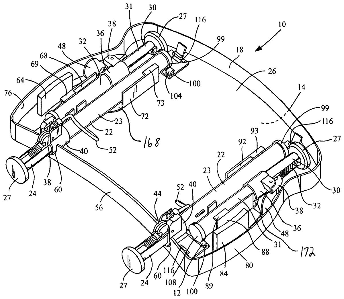
FIG. 5shows a perspective view of the underside26of the disclosed portable video game table10. A first lever64is shown in operable communication with the underside26of the table. The first lever64is in operable communication with a first rotatable plate168, most clearly seen inFIG. 8. The first rotatable plate168is rotatably attached to the underside26of the table surface14. Extending generally perpendicularly from the first rotatable plate (in a direction away from the table surface14) is a first sofa leg retainer68and a first floor leg retainer72. The first sofa leg retainer68holds a sofa leg30in place, and adjacent to the underside26of the table10. The first sofa leg retainer68has a first sofa leg retainer lip69, which allows the first sofa leg retainer68to hold a sofa leg30in place, and adjacent to the underside26of the table10. The first floor leg retainer72has a first floor leg retainer lip73, which allows the first floor leg retainer72to hold a floor leg22in place, and adjacent to the underside26of the table10. In order to release the legs22,30, a user moves the first lever64towards the right table lip76, this causes the first rotatable plate168to rotate, which causes the first sofa leg retainer68to move towards the right table lip76and free the sofa leg held in place by the first sofa leg retainer68; this also causes the first floor leg retainer72to move towards the left table lip80and free the floor leg which was held in place by the first floor leg retainer72. Similarly, there is a second lever84in operable communication with the underside26of the table. The second lever84is in operable communication with a second rotatable plate172, most clearly seen inFIG. 8. The second rotatable plate172is rotatably attached to the underside26of the table surface14. Extending generally perpendicularly from the first rotatable plate (in a direction away from the table surface14) is a second sofa leg retainer88and a second floor leg retainer92. The second sofa leg retainer88holds a sofa leg30in place, and adjacent to the underside26of the table10. The second sofa leg retainer88has a second sofa leg retainer lip89, which allows the first sofa leg retainer88to hold a sofa leg30in place, and adjacent to the underside26of the table10. The second floor leg retainer92has a second floor leg retainer lip93, which allows the second floor leg retainer92to hold a floor leg22in place, and adjacent to the underside26of the table10. In order to release the legs22,30held in place by the second sofa leg retainer88, and second floor leg retainer92, a user moves the second lever84towards the left table lip80, this causes the second rotatable plate172to rotate, which causes the second sofa leg retainer88to move towards the left table lip80and free the sofa leg30; this also causes the second floor leg retainer92to move towards the right table lip76and free the floor leg22. One of ordinary skill in the art will recognized that the disclosed invention may be modified such that the first lever64and second lever84may be moved in other directions, pushed, pulled, pressed, or lifted in order to release the retainers72,88, and/or release the locking mechanisms44.
Also shown inFIG. 5, are the pivot mechanisms for the legs22,30. A relatively unobstructed view of a pivot mechanism for a floor leg22is shown on the floor leg22nearest to the right lip76. The floor leg22nearest the left lip80has a similar pivot mechanism. The top99of the upper leg23of the floor leg is attached to a pivot rod100. The pivot rod100is in rotative communication with at least one floor leg sleeve104. Floor leg sleeve104is fixedly attached to the underside26of the disclosed portable video game table10. A relatively unobstructed view of a pivot mechanism for a sofa leg30is shown with respect to the sofa leg30nearest the left lip80. The top108of upper sofa leg31is attached to a pivot rod100. The pivot rod100is in rotative communication with at least one sofa leg sleeve112. The at least one sleeve112is in fixed communication with the underside26of the disclosed portable video game table10. A similar pivot mechanism is in communication with sofa leg30nearest the right lip76.
The disclosed portable video game table may also have clips116positioned on the underside26to hold the legs22,30in place when the legs are pivoted out of the retainers88,92. The clips116may be configured to snap or otherwise attach to the tops99of upper floor legs23, and to the tops108of the upper sofa leg31.
FIG. 6shows another perspective view of the underside26of the disclosed portable video game table10, but this view is from the front of the table.
FIG. 7shows a top view of the underside26of the disclosed portable video game table10.
FIG. 8shows a rear perspective view of the underside26of the disclosed portable video game table10. In this view, the legs22,30are shown pivoted out of the retainers88,92. Additionally, the lower floor legs24, and lower sofa legs32are shown extended out of the upper floor legs23and upper sofa legs31respectively. One of ordinary skill in the art will recognize that the legs22,30are telescoping legs. In this view, one can see that one of the two locking cables53is in operational communication with the first lever64(similarly, second lever84is operational communication with the other locking cable53) via the first sofa leg retainer68. When the first lever64is moved towards the right lip76, the locking cable53will develop a tension that is transferred to the locking mechanism38.
FIG. 9shows a close-up perspective view of the locking mechanism38(which is similar to the locking mechanism44). The locking cable sleeve52is held in place by a cable sleeve collar120that is coupled to the locking mechanism housing124. The cable53has an anchor128located on a first end132of the cable53. The anchor128is attached to a pinion136. The pinion136has a plurality of teeth148. The pinion is rotatable about a pivot point140located on the locking mechanism housing124. In this Figure, the pinion136is shown mated to the rack144located on the lower floor leg24. The rack144has a plurality of teeth148configured to mate with the pinion136. When the pinion136is mated to the rack144as shown inFIG. 9, the lower floor leg24is locked relative to the upper floor leg23. When the first lever64is moved towards the right lip76, tension is exerted on the cable53. The tension causes the anchor128to make the pinion136pivot about the pivot point140, thereby causing the pinion136to become disengaged from the rack144. Once the pinion136is disengaged from the rack144, the user can adjust the telescoping lower floor leg24with respect to the upper floor leg23. Once a suitable length of the leg22is reached, the user can release the first lever64, whereby the pinion136reengages with the rack144, and locks the lower floor leg24with respect to the upper floor leg23.FIG. 10shows the pinion136disengaged from the rack144. This rack and pinion locking system may be used on both the sofa legs30and the floor legs22. Of course, other means for extending and locking the legs in place may be used. On each of the sofa legs, instead of using a cable53, each sofa leg lever48is attached to a pinion136such that when the lever48is rotated about its pivot point, the pinion136rotates about its pivot point so that it the pinion136disengages from a rack located on the lower sofa legs32. One of ordinary skill in the art will recognized that the cable53and cable sleeve52are just one of many actuating means that may be used to engage and disengage the pinion136from the rack144.
FIG. 11shows a side view of the disclosed portable video game table10with the internal components visible. A compression spring152is shown inside the upper floor leg23. A compression spring156is shown inside the upper sofa leg31. The compression spring152,156are configured so that when the pinions136are disengaged from the racks144, the lower sofa leg32will automatically telescope out with respect to upper sofa legs31. Therefore, if one is seated on a seating surface, such as a sofa for example, holding the folded up table10in front of him or her, the legs22,30will extend until the spring-loaded floor legs22impinge the floor or other surface.
To operate the disclosed portable video game table10, one would hold the table10in an upright position, and pull move the first and second levers64,84towards the right lip76and left lip80respectively to allow the legs22,30to disengage from the retainers68,72and swing away from the underside26of the table10. At this point, the first and second levers64,84may be moved further towards the right lip76and the left lip80respectively, allowing the pinions136on the floor legs to disengaged from the racks144located on the lower floor legs24, thereby allowing the lower floor legs24to move freely relative to the upper floor legs23. Once the proper length of the floor legs is achieved, the first and second levers64,84maybe released, thereby locking the floor legs22in place. Now the sofa leg levers48may be rotated, to release the pinions136on the sofa legs30from the racks144located on the lower sofa legs30. Once the proper length of the sofa legs30are achieved, the levers48may be moved back to their locked position, thereby causing the pinions136to engage the racks144on the lower sofa legs32, and lock the lower sofa legs32in place relative to the upper sofa legs31. The legs,22,30, will swing freely, still attached to the undersigned by brackets46, which allow the legs to rotate freely. The legs22,30may be spring loaded with a torsion spring to rotate the legs into a fixed position approximately 95 degrees from horizontal, and held in place either by the spring force, or a detent design, or both.) The feet27may have a non-skid surface. The feet27may be able to pivot with respect to the lower legs24,32via a pivot attachment, or a universal joint.
FIG. 12shows the disclosed table10being used by a user160. The spring-loaded floor legs22are extended to the floor. The spring-loaded sofa legs30are extended to the sofa164, adjacent to the user160.
The disclosed portable video game table10is advantageous in that it may be used while sitting on the ground, in a chair, or on a stool. Additionally, it is portable, in that it can fold to a very small shape, with the legs folded in and against the underside26of the table surface14. The table10is easily adjustable due to the levers and the rack and pinion locking system.
While the disclosure has been described with reference to several embodiments, it will be understood by those skilled in the art that various changes may be made and equivalents may be substituted for elements thereof without departing from the scope of the disclosure. In addition, many modifications may be made to adapt a particular situation or material to the teachings of the disclosure without departing from the essential scope thereof. Therefore, it is intended that the disclosure not be limited to the particular embodiments disclosed as the best mode contemplated for carrying out this disclosure, but that the disclosure will include all embodiments falling within the scope of the appended claims.
Claims
- A portable video game table comprising: a table surface with an underside;a first spring-loaded floor leg rotateably attached to the underside, the first spring-loaded floor leg comprising: an upper floor leg;a floor leg collar in communication with the upper floor leg;a lower floor leg in communication with the floor leg collar, and in telescoping communication with the upper floor leg;a first compression spring located inside of the upper floor leg, and exerting a force on the lower floor leg that tends to telescope the lower floor leg out from the upper floor leg;a first spring-loaded sofa leg rotateably attached to the underside, the first spring-loaded sofa leg comprising: an upper sofa leg;a sofa leg collar in communication with the upper sofa leg;a lower sofa leg in communication with the sofa leg collar, and in telescoping communication with the upper sofa leg;a second compression spring located inside of the upper sofa leg, and exerting a force on the lower sofa leg that tends to telescope the lower sofa leg out from the upper sofa leg;a floor leg locking mechanism located on the first spring-loaded floor leg;a sofa leg locking mechanism located on the first spring-loaded sofa leg;a second spring-loaded floor leg rotateably attached to the underside, the second spring-loaded floor leg comprising: an upper floor leg;a floor leg collar in communication with the upper floor leg;a lower floor leg in communication with the floor leg collar, and in telescoping communication with the upper floor leg;a second compression spring located inside of the upper floor leg, and exerting a force on the lower floor leg that tends to telescope the lower floor leg out from the upper floor leg;a second spring-loaded sofa leg rotateably attached to the underside, the second spring-loaded sofa leg comprising: an upper sofa leg;a sofa leg collar in communication with the upper sofa leg;a lower sofa leg in communication with the sofa leg collar, and in telescoping communication with the upper sofa leg;a second compression spring located inside of the upper sofa leg, and exerting a force on the lower sofa leg that tends to telescope the lower sofa leg out from the upper sofa leg;a floor leg locking mechanism located on the second spring-loaded floor leg;a sofa leg locking mechanism located on the second spring-loaded sofa leg;a first rotatable plate located rotatably attached to the underside;a first lever in communication with the first rotatable plate;a first sofa leg retainer in communication with the first lever and the first rotatable plate;a first sofa leg retainer lip attached to the first sofa leg retainer, wherein the first sofa leg retainer lip releaseably holds the first sofa leg in the sofa leg retainer, adjacent to the underside, and wherein the first lever, the first sofa leg retainer, and the first sofa leg retainer lip can be rotated away from the first sofa leg via the first rotatable plate, thereby releasing the first sofa leg from the first sofa leg retainer lip, and further allowing the sofa leg to swing away from the underside;a first floor leg retainer in communication with the first lever and the first rotatable plate;a first floor leg retainer lip attached to the first floor leg retainer, wherein the first floor leg retainer lip releaseably holds the first floor leg in the first floor leg retainer, adjacent to the underside, and wherein the first lever, the first floor leg retainer, and the first floor leg retainer lip can be rotated away from the first floor leg via the first rotatable plate, thereby releasing the first floor leg from the first floor leg retainer lip, and further allowing the floor leg to swing away from the underside;a second rotatable plate rotatably attached to the underside;a second lever in communication with the second rotatable plate;a second sofa leg retainer in communication with the second lever and the second rotatable plate;a second sofa leg retainer lip attached to the second sofa leg retainer, wherein the second sofa leg retainer lip releaseably holds the second sofa leg in the sofa leg retainer, adjacent to the underside, and wherein the second lever, the second sofa leg retainer, and the second sofa leg retainer lip can be rotated away from the second sofa leg via the second rotatable plate, thereby releasing the second sofa leg from the second sofa leg retainer lip, and further allowing the sofa leg to swing away from the underside;a second floor leg retainer in communication with the second lever and the second rotatable plate;a second floor leg retainer lip attached to the second floor leg retainer, wherein the second floor leg retainer lip releaseably holds the second floor leg in the second floor leg retainer, adjacent to the underside, and wherein the second lever, the second floor leg retainer, and the second floor leg retainer lip can be rotated away from the second floor leg via the second rotatable plate, thereby releasing the second floor leg from the second floor leg retainer lip, and further allowing the floor leg to swing away from the underside;and wherein the table is configured such that the portable video game table can change to and from a folded configuration and a ready-for-use extended configuration.
- The portable video game table of claim 1 , where the length of the at least one spring-loaded floor leg is adjustable, and where the length of the one spring-loaded sofa leg is adjustable.
- The portable video game table of claim 1 , wherein the floor leg locking mechanism comprises: a locking mechanism housing attached to the floor leg collar;a floor leg rack located on the lower floor leg;a floor leg pinion in rotatable communication with the locking mechanism housing, and configured to releasably mate with the floor leg rack;an floor leg actuating means in operable communication with the floor leg pinion, and configured to disengage the floor leg pinion from mating with the floor leg rack when actuated, and further configured to mate the floor leg pinion to the floor leg rack when non-actuated;wherein the sofa leg locking mechanism comprises: a locking mechanism housing attached to the sofa leg collar;a sofa leg rack located on the lower sofa leg;a sofa leg pinion in rotatable communication with the locking mechanism housing, and configured to releasably mate with the sofa leg rack;and a sofa leg actuating means in operable communication with the sofa leg pinion, and configured to disengage the sofa leg pinion from mating with the sofa leg rack when actuated, and further configured to mate the sofa leg pinion to the sofa leg rack when non-actuated.
- The portable video game table of claim 3 , wherein the floor leg actuating means is a tension cable in operable communication with the floor leg pinion, and the at least one lever located on the underside.
- The portable video game table of claim 3 , wherein the sofa leg actuating means is a sofa leg lever in operable communication with the sofa leg pinion, and sofa leg lever is rotateably attached to the sofa leg collar.
- The portable video game table of claim 1 , wherein each of the legs has a foot with a non-skid surface.
- The portable video game table of claim 3 , wherein the sofa leg pinion has a plurality of teeth configured to mate with a plurality of teeth located on the sofa leg rack, and wherein the floor leg pinion has a plurality of teeth configured to mate with a plurality of teeth located on the floor leg rack.
- A portable video game table comprising: a table surface with an underside;a first floor leg sleeve attached to the underside;a first pivot rod in rotatable communication with the first floor leg sleeve;a first upper floor leg top in communication with the first pivot rod;a first upper floor leg in communication with the first upper floor leg top;a first floor leg collar in communication with the first upper floor leg;a first lower floor leg in telescoping communication with the first upper floor leg, and in communication with the first floor leg collar;a first compression spring located inside of the upper floor leg, and exerting a force on the lower floor leg that tends to telescope the lower floor leg out from the upper floor leg;a first floor leg clip attached to the underside and configured to allow the first upper floor leg top to releasably snap into the clip;a first floor leg locking mechanism housing attached to the first floor leg collar;a first floor leg rack located on the first lower floor leg;a first floor leg pinion in rotatable communication with the first floor leg locking mechanism housing, and configured to releasably mate with the first floor leg rack;a first rotatable plate rotatably attached to the underside;a first tension cable in operable communication with the first floor leg pinion, and a first lever located on the underside;a first sofa leg sleeve attached to the underside;a first pivot rod in rotatable communication with the first sofa leg sleeve;a first upper sofa leg top in communication with the first pivot rod;a first upper sofa leg in communication with the first upper sofa leg top;a first sofa leg collar in communication with the first upper sofa leg;a first lower sofa leg in telescoping communication with the first upper sofa leg, and in communication with the first sofa leg collar;a second compression spring located inside of the upper sofa leg, and exerting a force on the lower sofa leg that tends to telescope the lower sofa leg out from the upper sofa leg;a first sofa leg clip attached to the underside and configured to allow the first upper sofa leg top to releasably snap into the clip;a first floor leg locking mechanism housing attached to the first sofa leg collar;a first sofa leg rack located on the first lower sofa leg;a first sofa leg pinion in rotatable communication with the first sofa leg locking mechanism housing, and configured to releasably mate with the first sofa leg rack;a first sofa leg lever attached to the first sofa leg collar, and in operable communication with the first sofa leg pinion;a first sofa leg retainer in operable communication with the first lever and the first rotatable plate;a first sofa leg retainer lip located on the first sofa leg retainer;wherein the first sofa leg retainer is configured to releasably hold the first sofa leg in a folded position against the underside, and wherein the first lever, the first sofa leg retainer, and the first sofa leg retainer lip can be rotated away from the first sofa leg via the first rotatable plate, thereby releasing the first sofa leg from the first sofa leg retainer lip;a first floor leg retainer in operable communication with the first lever and the first rotatable plate;a first floor leg retainer lip located on the first floor leg retainer;wherein the first floor leg retainer is configured to releasably hold the first floor leg in a folded position against the underside, and wherein the first lever, the first floor leg retainer, and the first floor leg retainer lip can be rotated away from the first floor leg via the first rotatable plate, thereby releasing the first floor leg from the first floor leg retainer lip;a first sofa leg clip fixed to the underside, and configured to allow the first sofa leg top to releasably snap into the first sofa leg clip;a first floor leg clip fixed to the underside, and configured to allow the first floor leg top to releasably snap into the first floor clip;a second floor leg sleeve attached to the underside;a second pivot rod in rotatable communication with the second floor leg sleeve;a second upper floor leg top in communication with the second pivot rod;a second upper floor leg in communication with the second upper floor leg top;a second floor leg collar in communication with the second upper floor leg;a second lower floor leg in telescoping communication with the second upper floor leg, and in communication with the second floor leg collar;a second floor leg clip attached to the underside and configured to allow the second upper floor leg top to releasably snap into the clip;a second floor leg locking mechanism housing attached to the second floor leg collar;a second floor leg rack located on the second lower floor leg;a second floor leg pinion in rotatable communication with the second floor leg locking mechanism housing, and configured to releasably mate with the second floor leg rack;a second rotatable plate rotatably attached to the underside;a second tension cable in operable communication with the second floor leg pinion, and a second lever located on the underside;a second sofa leg sleeve attached to the underside;a second pivot rod in rotatable communication with the second sofa leg sleeve;a second upper sofa leg top in communication with the second pivot rod;a second upper sofa leg in communication with the second upper sofa leg top;a second sofa leg collar in communication with the second upper sofa leg;a second lower sofa leg in telescoping communication with the second upper sofa leg, and in communication with the second sofa leg collar;a second sofa leg clip attached to the underside and configured to allow the second upper sofa leg top to releasably snap into the clip;a second floor leg locking mechanism housing attached to the second sofa leg collar;a second sofa leg rack located on the second lower sofa leg;a second sofa leg pinion in rotatable communication with the second sofa leg locking mechanism housing, and configured to releasably mate with the second sofa leg rack;a second sofa leg lever attached to the second sofa leg collar, and in operable communication with the second sofa leg pinion;a second sofa leg retainer in operable communication with the second lever and the second rotatable plate;a second sofa leg retainer lip located on the second sofa leg retainer;wherein the second sofa leg retainer is configured to releasably hold the second sofa leg in a folded position against the underside, and wherein the second lever, the second sofa leg retainer, and the second sofa leg retainer lip can be rotated away from the second sofa leg via the second rotatable plate, thereby releasing the second sofa leg from the second sofa leg retainer lip;a second floor leg retainer in operable communication with the second lever and the second rotatable plate;a second floor leg retainer lip located on the second floor leg retainer;wherein the second floor leg retainer is configured to releasably hold the second floor leg in a folded position against the underside, and wherein the second lever, the second floor leg retainer, and the second floor leg retainer lip can be rotated away from the second floor leg via the second rotatable plate, thereby releasing the second floor leg from the second floor leg retainer lip;a second sofa leg clip fixed to the underside, and configured to allow the second sofa leg top to releasably snap into the second sofa leg clip;and a second floor leg clip fixed to the underside, and configured to allow the floor leg top to releasably snap into the second floor clip.
Disclaimer: Data collected from the USPTO and may be malformed, incomplete, and/or otherwise inaccurate.