U.S. Pat. No. 8,020,711
CONTROLLER RETAINER FOR A VIDEO GAME REMOTE CONTROLLER ASSEMBLY
Issue DateJuly 2, 2007
Illustrative Figure
Abstract
A controller retainer (14) for a video game controller (12) includes a retainer top (20), a retainer bottom (22), a first side (24), a second side (26), a retainer back (28) and a retainer front (30). The retainer top (20) includes a controller receiver (34) that receives the controller (12). The first side (24) and the second side (26) extend between the retainer top (20) and the retainer bottom (22). The second side (26) can be non-parallel to the first side (24). At least one of the sides (24, 26) can form an angle (44, 48) that is greater than 90 degrees relative to the retainer bottom (22). At least one of the sides (24, 26) can form an angle (250, 254) that is less than 90 degrees relative to the retainer back (28). The retainer bottom (22) can include a first surface (36) and a second surface (38) that is positioned at an angle greater than 90 degrees relative to the first surface (36). The controller receiver (14) can include one or more cavities (358) that each substantially encircles at least a portion of the controller (12).
Description
DESCRIPTION FIG. 1is a perspective view of one embodiment of a video game remote controller assembly10(sometimes referred to herein as a “controller assembly”) positioned on a support surface11. As used herein, the support surface11can be any surface that supports the controller assembly, such as a table, a floor, the lap of a user, or any other suitable surface. The design of the controller assembly10can be varied. In the embodiment illustrated inFIG. 1, the controller assembly10includes a video game remote controller12(sometimes referred to herein as a “controller”) and a controller retainer14. InFIG. 1, the controller retainer14is partially illustrated in phantom to more easily identify the structures that form the controller retainer14. The controller12remotely controls on-screen movements of video objects during play of a video game by a user. The shape and size of the controller12can vary to suit the design requirements of the controller assembly10. The controller12can include an electrical connector16and one or more switches18. The connector16electrically connects the controller12to a console (not shown) or to a video display device (not shown) to facilitate transmission of electrical signals between the controller12and the console and/or video display device. Alternatively, the controller can wirelessly send signals to the console and/or video display device by using IR, RF or other electromagnetic radiation, as non-exclusive examples. The switches18can include various types of actuators such as pushbuttons, joysticks, wheels, dials and/or other types of control mechanisms that are used to control various aspects of the video game being played. The controller retainer14retains the controller12. The size and shape of the controller retainer14can be varied to suit the design requirements of the controller12. In the embodiment illustrated inFIG. 1, the controller retainer includes a retainer top20, a retainer bottom22(illustrated in phantom), a first side24, a second side26(illustrated in phantom), a retainer back28and a retainer front30(illustrated in phantom). ...
DESCRIPTION
FIG. 1is a perspective view of one embodiment of a video game remote controller assembly10(sometimes referred to herein as a “controller assembly”) positioned on a support surface11. As used herein, the support surface11can be any surface that supports the controller assembly, such as a table, a floor, the lap of a user, or any other suitable surface.
The design of the controller assembly10can be varied. In the embodiment illustrated inFIG. 1, the controller assembly10includes a video game remote controller12(sometimes referred to herein as a “controller”) and a controller retainer14. InFIG. 1, the controller retainer14is partially illustrated in phantom to more easily identify the structures that form the controller retainer14.
The controller12remotely controls on-screen movements of video objects during play of a video game by a user. The shape and size of the controller12can vary to suit the design requirements of the controller assembly10. The controller12can include an electrical connector16and one or more switches18. The connector16electrically connects the controller12to a console (not shown) or to a video display device (not shown) to facilitate transmission of electrical signals between the controller12and the console and/or video display device. Alternatively, the controller can wirelessly send signals to the console and/or video display device by using IR, RF or other electromagnetic radiation, as non-exclusive examples. The switches18can include various types of actuators such as pushbuttons, joysticks, wheels, dials and/or other types of control mechanisms that are used to control various aspects of the video game being played.
The controller retainer14retains the controller12. The size and shape of the controller retainer14can be varied to suit the design requirements of the controller12. In the embodiment illustrated inFIG. 1, the controller retainer includes a retainer top20, a retainer bottom22(illustrated in phantom), a first side24, a second side26(illustrated in phantom), a retainer back28and a retainer front30(illustrated in phantom).
The retainer top20retains and positions the controller12so that the controller12is visible to and/or faces the user during play. The retainer top20extends between the first side24and the second side26, and between the retainer back28and the retainer front30. In the embodiment illustrated inFIG. 1, the retainer top20includes a substantially planar top surface32and a controller receiver34. Alternatively, the top surface32of the retainer top20can have a non-planar configuration. In non-exclusive alternative embodiments, for example, the top surface32can be concave, convex, ridged, or the top surface can combine two or more of these types of configurations. Still alternatively, the top surface32can have any other suitable configuration.
The controller receiver34can include a cutout, indentation, depression or other configuration so that the controller receiver34receives the controller12. In certain embodiments, the controller receiver34securely positions the controller12so that movement of the controller12relative to the controller retainer14during use is at least partially, if not fully, inhibited.
The retainer bottom22is generally on an opposing side of the controller retainer14from the retainer top20. The retainer bottom22extends between the first side24and the second side26, and between the retainer back28and the retainer front30. In the embodiment illustrated inFIG. 1, the retainer bottom22includes a first bottom surface36(illustrated in phantom) and an adjacent second bottom surface38(illustrated in phantom). The first bottom surface36can rest on the user during play when the user is in a seated position or another suitable position. In one embodiment, the first bottom surface36is substantially planar and is substantially parallel to the top surface32. Alternatively, the first bottom surface36can be non-planar and/or non-parallel to the top surface32.
In this embodiment, the second bottom surface38is angled relative to the first bottom surface36. For example, the second bottom surface38can be positioned at an angle40that is greater than 90 degrees and less than 180 degrees relative to the first bottom surface. In various non-exclusive examples, the second bottom surface38can be positioned at an angle relative to the first bottom surface36that is less than 180 degrees, but is at least approximately 100, 120, 135, 150 or 170 degrees. Still alternatively, the second bottom surface38can be positioned at an angle relative to the first bottom surface36that is less than or equal to 90 degrees, or greater than or equal to 180 degrees. In certain embodiments, the second bottom surface38provides a more comfortable surface for the user's hands while using the controller, as described in greater detail below.
In the embodiment illustrated inFIG. 1, the first side24extends between the retainer top20and the retainer bottom22. In one embodiment, the first side24can be substantially planar. Alternatively, the first side24can have a non-planar configuration. In certain embodiments, the first side24is non-perpendicular relative to (i) the top surface32of the retainer top20, and (ii) the retainer bottom22. In this embodiment, the first side24forms an acute angle42with the top surface32, and forms an obtuse angle44with the retainer bottom22. In non-exclusive alternative embodiments, the angle42between the first side24and the top surface32is less than 90 degrees and greater than approximately 30, 45, 60, 70 or 80 degrees. Still alternatively, the angle42between the first side24and the top surface32is equal to or greater than 90 degrees, or less than 30 degrees.
In non-exclusive alternative embodiments, the angle44between the first side24and the retainer bottom22is greater than 90 degrees and less than approximately 100, 110, 120, 135 or 150 degrees. Still alternatively, the angle44between the first side24and the retainer bottom22is equal to or less than 90 degrees, or greater than 150 degrees.
In the embodiment illustrated inFIG. 1, the second side26extends between the top surface32of the retainer top20and the retainer bottom22. In one embodiment, the second side26can be substantially planar. Alternatively, the second side26can have a non-planar configuration. In the embodiment illustrated inFIG. 1, the second side26is non-perpendicular relative to the top surface32and the retainer bottom22. In this embodiment, the second side26forms an acute angle46with the top surface32, and forms an obtuse angle48with the retainer bottom22. In non-exclusive alternative embodiments, the angle46between the second side26and the top surface32is less than 90 degrees and greater than approximately 30, 45, 60, 70 or 80 degrees. Still alternatively, the angle46between the second side26and the top surface32is equal to or greater than 90 degrees, or less than 30 degrees.
In non-exclusive alternative embodiments, the angle48between the second side26and the retainer bottom22is greater than 90 degrees and less than approximately 100, 110, 120, 135 or 150 degrees. Still alternatively, the angle48between the second side26and the retainer bottom22is equal to or less than 90 degrees, or greater than 150 degrees.
It is understood that although the first side24and the second side26can be substantially mirror images of one another, this is not necessary. For example, angle42and angle46can be identical to or different from one another. Somewhat similarly, angle44and angle48can be identical to or different from one another.
In one embodiment, the retainer back28is substantially planar. Alternatively, the retainer back28can have a non-planar configuration. The retainer back28can have a trapezoidal shape, as illustrated inFIG. 1. Alternatively, the retainer back28can have a different geometric shape, such as rectangular, elliptical, circular, rhomboidal, or any other suitable geometric configuration. In one embodiment, the retainer back28provides a surface that can rest against the user's midsection during use of the controller assembly10.
In certain embodiments, the retainer front30can include one or more planar or non-planar surfaces that are oriented substantially opposite the retainer back28. In one embodiment, the retainer front30is substantially parallel to the retainer back28. Alternatively, the retainer front30can be non-parallel to the retainer back28or can have portions that are parallel and non-parallel to the retainer back28.
The material(s) used to form the controller retainer14can vary. In one embodiment, the controller retainer14can be formed from a resilient plastic material, such as memory foam or another closed-cell or open-cell foam-based material. Alternatively, the controller retainer14can be formed from other suitable materials, such as wood, metal, ceramic or any other suitable natural or synthetic material(s), as non-exclusive examples.
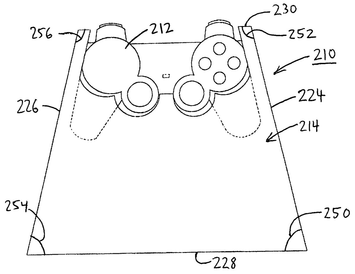
FIG. 2is a top view of one embodiment of the controller assembly210. In this embodiment, the controller assembly210includes the controller212and the controller retainer214. The controller212can be substantially similar to the controller12previously described. In the embodiment illustrated inFIG. 2, the controller retainer214includes a first side224, a second side226, a retainer back228and a retainer front230. In one embodiment, the first side224forms an angle250that is less than 90 degrees relative to the retainer back228. For example, in non-exclusive alternative embodiments, the angle250between the first side224and the retainer back228is less than 90 degrees and greater than approximately 30, 45, 60, 70 or 80 degrees. Still alternatively, the angle250between the first side224and the retainer back228can be equal to or greater than 90 degrees, or less than 30 degrees.
In certain embodiments, the first side224forms an angle252that is greater than 90 degrees relative to the retainer front230. For example, in non-exclusive alternative embodiments, the angle252between the first side224and the retainer back228is greater than 90 degrees and less than approximately 100, 110, 120, 135 or 150 degrees. Still alternatively, the angle252between the first side224and the retainer front230can be less than or equal to 90 degrees, or greater than 150 degrees.
In one embodiment, the second side226forms an angle254that is less than 90 degrees relative to the retainer back228. For example, in non-exclusive alternative embodiments, the angle254between the second side226and the retainer back228is less than 90 degrees and greater than approximately 30, 45, 60, 70 or 80 degrees. Still alternatively, the angle254between the second side226and the retainer back228can be equal to or greater than 90 degrees, or less than 30 degrees.
In certain embodiments, the second side226forms an angle256that is greater than 90 degrees relative to the retainer front230. For example, in non-exclusive alternative embodiments, the angle256between the second side226and the retainer back228is greater than 90 degrees and less than approximately 100, 110, 120, 135 or 150 degrees. Still alternatively, the angle256between the second side226and the retainer front230can be less than or equal to 90 degrees, or greater than 150 degrees.
In the embodiment illustrated inFIG. 2, for example, the shape of the controller retainer214allows a user to more comfortably control the controller212. For instance, because the first side224and the second side226form acute angles250,254with the retainer back228and obtuse angles252,256with the retainer front230, the controller retainer214more naturally follows the position of the arms of the user. Stated another way, when the retainer back228is abutted against the midsection of seated user, the forearms of the user comfortably extend along the sides224,226toward the controller212. Greater comfort for the user can allow for a longer duration of use of the controller assembly210, less strain and/or less fatigue.
FIG. 3Ais a top view of one embodiment of the controller retainer314with the controller12(illustrated inFIG. 1, for example) omitted for clarity. In this embodiment, the controller retainer314includes a retainer top320having a top surface332and a controller receiver334. Further, in the embodiment illustrated inFIG. 3A, the controller receiver334includes a plurality of receiver cavities358(two receiver cavities358are illustrated in phantom inFIG. 3A). In alternative embodiments, the controller receiver334can include fewer than or greater than two receiver cavities358.
The receiver cavities358each receives a portion of the controller12. In certain embodiments, the receiver cavities358can encircle a portion of the controller12. In these embodiments, the receiver cavities358securely retain the controller12, allowing the controller retainer314to further stabilize the controller12during use by the user. Because of the shape of the controller retainer314as provided herein, movement of the controller retainer314during use is inhibited. As a consequence, in certain embodiments, overall unwanted movement of the controller12relative to the user is likewise inhibited, which can result in fewer errors by the user during usage.
FIG. 3Bis a cross-sectional view of the controller retainer314taken on line3B-3B inFIG. 3A.FIG. 3Billustrates that the receiver cavity358can have a contour that is substantially similar to a contour of a portion of the controller12(illustrated inFIG. 1, for example). In this embodiment, the controller12can snugly fit within the controller receiver334so that movement of the controller12relative to the controller retainer314is inhibited.
Further, in this embodiment, the controller retainer314can include a retainer body360and a retainer cover362that partially or fully covers the retainer body360. The retainer cover362can be removable or the retainer cover362can be permanently or semi-permanently secured to the retainer body360. The retainer cover362can be formed from any suitable material, including various natural or synthetic textiles and/or fabrics, as non-exclusive examples.
Additionally, in this embodiment, the retainer bottom322includes a first bottom surface336and an adjacent second bottom surface338. In this embodiment, the second bottom surface338is obtusely angled relative to the first bottom surface336and/or the retainer front330. This configuration promotes the user to hold the controller retainer314in a more relaxed manner, decreasing the propensity for or completely avoiding a “claw-like” grip on the controller12, which can occur absent one or more of the configurations of the controller retainer314described herein.
Further, in certain embodiments, the controller retainer314raises the controller12above the support surface11(illustrated inFIG. 1). For example, the controller retainer314can be configured to raise the controller to a comfortable level above the lap of the user, to reduce arm and/or shoulder fatigue of the user. In one embodiment, the controller receiver334has a height372that is less than a height374of the controller retainer314. In non-exclusive alternative embodiments, the height372of the controller receiver334is less than approximately 75%, 50%, 40%, 30% or 25% of the height374of the controller retainer314.
Further, the controller retainer314has a retainer volume, and the controller12has a controller volume. In certain embodiments, the retainer volume is greater than the controller volume. In non-exclusive alternative embodiments, the retainer volume is at least approximately 25%, 50%, 100%, 150%, 200%, 300% or 500% greater than the controller volume. In these embodiments, because the controller retainer314has a greater volume than the controller12, and because the controller12is secured to the controller retainer314, movement of the controller retainer314is reduced and stability of the controller12is increased during use. In an alternative embodiment, the controller volume can be greater than the retainer volume.
FIG. 3Cis a cross-sectional view of the controller retainer314taken on line3C-3C inFIG. 3A. In this embodiment, the receiver cavities358can have a substantially circular or elliptical cross-sectional shape. In alternative embodiments, the receiver cavities358can have any suitable cross-sectional shape that accommodates and receives the particular controller12(illustrated inFIG. 1, for example) to form a snug fit.
FIG. 4Ais a top view of another embodiment of the controller assembly410. In this embodiment, the controller assembly410only includes a controller412, and omits the controller retainer14(illustrated inFIG. 1). In one embodiment, the controller412includes a controller body464that basically adopts the shape of one of the controller retainers described herein. Thus, the controller412and the controller retainer are essentially formed as an integral unit. With this design, the controller412provides one or more of the benefits previously described without the need for a separate controller retainer.
FIG. 4Bis a side view of the controller assembly410illustrated inFIG. 4A. In this embodiment, the controller412includes a controller bottom466having a first bottom surface468and a second bottom surface470that is angled relative to the first bottom surface468in a somewhat similar manner as previously described relative to one or more embodiments of the controller retainer. This configuration promotes the user to hold the controller412in a more relaxed manner, decreasing the propensity for or completely avoiding a “claw-like” grip on the controller412.
It is understood that although a number of different embodiments of the video game controller assembly and the controller retainer have been illustrated and described herein, one or more features of any one embodiment can be combined with one or more features of one or more of the other embodiment, provided that such combination satisfies the intent of the present invention.
While the particular video game controller assemblies as shown and disclosed herein are fully capable of obtaining the objects and providing the advantages herein before stated, it is to be understood that they are merely illustrative of the presently preferred embodiments of the invention and that no limitations are intended to the details of the methods, construction or design herein shown and described.
Claims
- A controller retainer for a video game controller, the controller retainer comprising: a retainer top including a controller receiver that receives the video game controller;a retainer bottom that is opposite the retainer top;a substantially planar first side that extends between the retainer top and the retainer bottom;a substantially planar second side that is opposite the first side, the second side extending between the retainer top and the retainer bottom, the second side being spaced apart from the first side, the second side being non-parallel relative to the first side;and a retainer back that extends between the first side and the second side and is positioned away from the controller receiver, the retainer back extending between the retainer top and the retainer bottom, the retainer back forming an angle with at least one of the first side and the second side that is less than 90 degrees.
- The controller retainer of claim 1 wherein the retainer back forms an angle with each of the first side and the second side that is less than 90 degrees.
- The controller retainer of claim 1 further comprising a retainer front that extends between the first side and the second side and is positioned adjacent to the controller receiver, the retainer front extending between the retainer top and the retainer bottom, the retainer front forming an angle with at least one of the first side and the second side that is greater than 90 degrees.
- The controller retainer of claim 1 wherein the retainer bottom includes a first surface and an adjacent second surface, the second surface being positioned at an angle that is greater than 90 degrees relative to the first surface.
- The controller retainer of claim 4 wherein the second surface is substantially planar.
- The controller retainer of claim 4 further comprising a retainer front that extends between the first side and the second side and is positioned adjacent to the controller receiver, wherein the second surface is positioned at an angle that is greater than 90 degrees relative to the retainer front.
- The controller retainer of claim 1 wherein the retainer bottom includes a first surface and an adjacent second surface, the second surface being positioned at an angle that is greater than 120 degrees relative to the first surface.
- The controller retainer of claim 1 wherein at least one of the first side and the second side forms an angle that is greater than 90 degrees relative to the retainer bottom.
- The controller retainer of claim 1 wherein the controller receiver includes a cavity that substantially encircles at least a portion of the controller.
- The controller retainer of claim 1 wherein the controller retainer has a retainer height measured in a first direction between the retainer top and the retainer bottom, and the controller receiver has a receiver height measured in the first direction that is less than approximately 50% of the retainer height.
- A controller retainer for a video game controller, the controller retainer comprising: a retainer top including a controller receiver that receives the video game controller;a retainer bottom that is opposite the retainer top;a retainer back that extends between the retainer top and the retainer bottom, the retainer back being positioned away from the controller receiver;a substantially planar first side that extends between the retainer top and the retainer bottom, the first side forming an angle with the retainer back that is less than 90 degrees;and a substantially planar second side that is spaced apart and opposite the first side, the second side extending between the retainer top and the retainer bottom, the second side being non-parallel relative to the first side.
- The controller retainer of claim 11 wherein the second side forms an angle with the retainer back that is less than 90 degrees.
- The controller retainer of claim 11 further comprising a retainer front that extends between the first side and the second side and is positioned adjacent to the controller receiver, the retainer front extending between the retainer top and the retainer bottom, the retainer front forming an angle with at least one of the first side and the second side that is greater than 90 degrees.
- The controller retainer of claim 11 wherein the retainer back is substantially planar.
- The controller retainer of claim 11 wherein the retainer bottom includes a first surface and an adjacent second surface, the second surface being positioned at an angle that is greater than 90 degrees relative to the first surface.
- The controller retainer of claim 15 wherein the second surface is substantially planar.
- The controller retainer of claim 15 further comprising a retainer front that extends between the first side and the second side and is positioned adjacent to the controller receiver, wherein the second surface is positioned at an angle that is greater than 90 degrees relative to the retainer front.
- The controller retainer of claim 11 wherein at least one of the first side and the second side forms an angle that is greater than 90 degrees relative to the retainer bottom.
- The controller retainer of claim 11 wherein the controller receiver includes a cavity that substantially encircles at least a portion of the controller.
- The controller retainer of claim 11 wherein the controller retainer has a retainer height measured in a first direction between the retainer top and the retainer bottom, and the controller receiver has a receiver height measured in the first direction that is less than approximately 50% of the retainer height.
- A controller retainer for a video game controller, the controller retainer comprising: a retainer top including a controller receiver that receives the video game controller, the controller receiver including a plurality of spaced apart cavities that substantially encircle at least a portion of the controller;a retainer bottom that is opposite the retainer top, the retainer bottom including a first bottom surface and a second bottom surface that is positioned at an angle relative to the first bottom surface, the angle being greater than 90 degrees;a substantially planar retainer back that extends between the retainer top and the retainer bottom, the retainer back being positioned away from the controller receiver;a substantially planar first side that extends between the retainer top and the retainer bottom, the first side forming an angle with the retainer back that is less than 90 degrees;a substantially planar second side that is spaced apart and opposite the first side, the second side extending between the retainer top and the retainer bottom, the second side forming an angle with the retainer back that is less than 90 degrees;and a retainer front that extends between the first side and the second side and is positioned adjacent to the controller receiver, the retainer front extending between the retainer top and the retainer bottom, the retainer front forming an angle with at least one of the first side and the second side that is greater than 90 degrees.
- A controller retainer for a video game controller, the controller retainer comprising: a retainer top including a controller receiver that receives the video game controller, the controller receiver including a cavity that substantially encircles at least a portion of the video game controller;a retainer bottom that is opposite the retainer top;a substantially planar first side that extends between the retainer top and the retainer bottom;and a substantially planar second side that is opposite the first side, the second side extending between the retainer top and the retainer bottom, the second side being spaced apart from the first side, the second side being non-parallel relative to the first side.
- The controller retainer of claim 22 wherein the controller receiver includes a plurality of spaced apart cavities that substantially encircle at least a portion of the controller.
Disclaimer: Data collected from the USPTO and may be malformed, incomplete, and/or otherwise inaccurate.