U.S. Pat. No. 7,988,556
GAME CONSOLE AND EMULATOR FOR THE GAME CONSOLE
AssigneeNintendo Co., Ltd.
Issue DateNovember 18, 2010
Illustrative Figure
Abstract
A portable game system includes two display screens, at least one of which is touch-sensitive. A memory card is selectively connectable to the portable game system.
Description
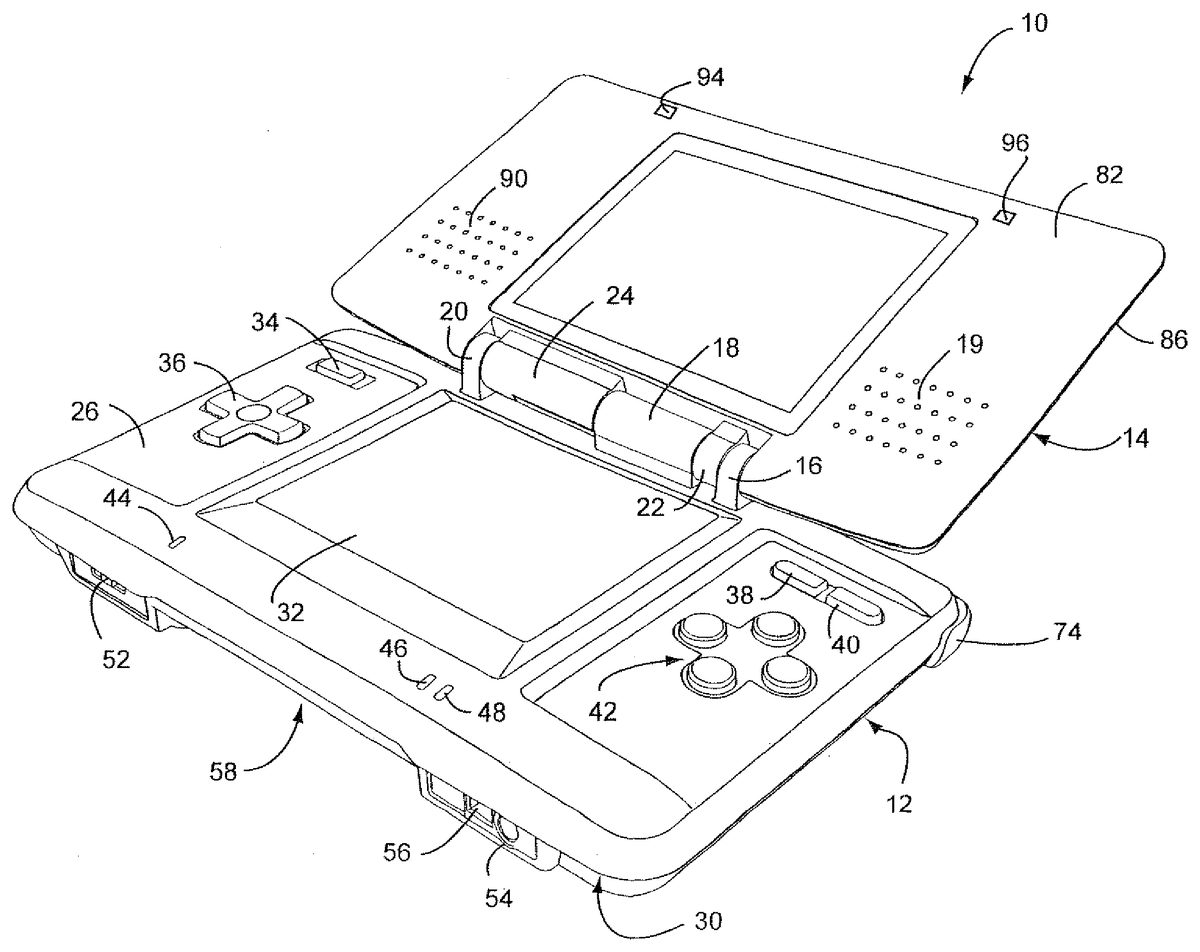
DETAILED DESCRIPTION OF EXAMPLE EMBODIMENTS Referring toFIGS. 1 and 2, in an illustrative example embodiment the game system or console10includes a main body12and a cover body14hingedly connected to each other along an upper edge of the main body12and a lower edge of the cover body14(references herein to terms such as “upper” and “lower” and “forward” and “rearward” are for ease of understanding and are made relative to an orientation of the game device where the cover body14is in an open position and the game is being held by a user in a normal operating position). Hinge elements16,18and20on the main body12mesh with hinge elements22and24on the cover body, with a hinge pin (not shown) extending through the aligned hinge elements in conventional fashion. Note that because hinge elements16,18and20extend from the upper (or inner) face26of the main body12, the cover body14overlies the upper face26when the cover body14is closed over the main body. When the cover body14is in its fully open position, it is substantially parallel to the main body12but lies in a substantially parallel, offset plane. The main body12also has a lower (or outer) face28(FIG. 2) and a peripheral edge30. A first display screen32is recessed within the upper face26of the main body12with dimensions of approximately 2 inches in length and 1⅞ inches in width, yielding a diagonal screen dimension of 3 inches. The screen in the example embodiment is a backlit (e.g., 40 candelas), color liquid crystal display (LCD) with a display resolution of 256×192 dots (aspect ratio 4:3). This screen is touch sensitive and may be activated by a stylus, described further herein. A power button34is located in the upper left corner of face26and is used to turn the game console on and off. A cross-shaped directional control button36is located adjacent and below the power button34, and is used for game play ...
DETAILED DESCRIPTION OF EXAMPLE EMBODIMENTS
Referring toFIGS. 1 and 2, in an illustrative example embodiment the game system or console10includes a main body12and a cover body14hingedly connected to each other along an upper edge of the main body12and a lower edge of the cover body14(references herein to terms such as “upper” and “lower” and “forward” and “rearward” are for ease of understanding and are made relative to an orientation of the game device where the cover body14is in an open position and the game is being held by a user in a normal operating position). Hinge elements16,18and20on the main body12mesh with hinge elements22and24on the cover body, with a hinge pin (not shown) extending through the aligned hinge elements in conventional fashion. Note that because hinge elements16,18and20extend from the upper (or inner) face26of the main body12, the cover body14overlies the upper face26when the cover body14is closed over the main body. When the cover body14is in its fully open position, it is substantially parallel to the main body12but lies in a substantially parallel, offset plane. The main body12also has a lower (or outer) face28(FIG. 2) and a peripheral edge30.
A first display screen32is recessed within the upper face26of the main body12with dimensions of approximately 2 inches in length and 1⅞ inches in width, yielding a diagonal screen dimension of 3 inches. The screen in the example embodiment is a backlit (e.g., 40 candelas), color liquid crystal display (LCD) with a display resolution of 256×192 dots (aspect ratio 4:3). This screen is touch sensitive and may be activated by a stylus, described further herein. A power button34is located in the upper left corner of face26and is used to turn the game console on and off. A cross-shaped directional control button36is located adjacent and below the power button34, and is used for game play control.
More specifically, display screen32includes a resistive-membrane touch panel that allows coordinates to be obtained in dot units. The touch panel can be operated with a finger or a stylus. The touch panel input data includes x-coordinate (e.g., 8 bits); y-coordinate (e.g., 8 bits); touch determination flag (e.g., 1 bit); and data validity flag (e.g., 2 bits). In the example portable game system, the touch panel must be pressed down with a force that exceeds a specified value, e.g., 80 g, for the location to be detected. The details of the input data for the touch panel are shown below:x-coordinate, y-coordinatex-coordinate: 0-255 (dots)y-coordinate: 0-191 (dots)touch determination flag0: the touch panel is not being touched1: the touch panel is being toucheddata validity flag00: both the x-coordinate and y-coordinate are valid01: the x-coordinate is invalid10: the y-coordinate is invalid11: both the x-coordinate and y-coordinate are invalid
FIGS. 27(a) and27(b) show an example touch panel structure which includes an upper film902, a lower film904, transparent conducting membranes906,908and dot spacers910. As shown inFIG. 27(a), normally, the space formed between the upper and lower films902,904, each of which is respectively coated with a transparent conducting membrane906,908(such as an indium-tin-oxide (ITO) membrane), prevents current from being conducted. When a finger or stylus presses on the panel as shown inFIG. 27(b), the pressure causes the upper and lower films to touch and conduct current. The dot spacers910prevent erroneous input and the example portable game system from being continuously on.
In the example portable game system, the touch panel structure extends over all or substantially all of the display screen. It is of course possible, if desired, to provide the touch input only over a portion of the display screen.
In the upper right corner of the main body12, there are side-by-side “start” and “select” buttons38,40, respectively, with X/Y/A/B buttons42located adjacent and below the “start” and “select” buttons. Buttons38,40and42are also used for game play control. A microphone44(which may, for example, be an omni-directional condenser microphone) is located below the left edge of screen32for use with specially designed games or other applications (e.g., voice chat) having a microphone feature. A battery recharge indicator LED46and a power indicator LED48are also located on the upper face26, adjacent the lower edge thereof, below the right edge of screen32.
With reference now especially toFIG. 3, a lower or forward portion50of the peripheral edge30(closest to the user) is provided with a volume control slide52and headphone and microphone connectors54,56on either side of a first game slot58. In the example portable game system, slot58is especially designed for larger game cartridges or cards originally designed for use with the assignee's Game Boy Advance® game system. Of course, slot28may be otherwise designed and the invention is not limited in this respect.
As best seen inFIG. 2, an upper or rearward portion60of the peripheral edge30is provided with an external extension connector62that permits connection to an AC adapter for recharging the internal battery (not shown), or for operating the game using household power. A second game slot64in edge portion60is designed for receiving memory or game cards especially designed for this example game system. The second game slot64is smaller than the first game slot58, reflecting the different sizes of the game cards. Openings66,68form an elbow-shaped through slot adapted for securing a wrist strap (not shown), thereby enabling the user to secure the game system to the body and thus minimize the potential for losing, misplacing or dropping the game system. A stylus port or holder, in the form of a blind bore70is located adjacent the wrist-strap mount for holding a stylus71(FIG. 5) before or after use.
The stylus71is a plastic pencil-shaped device with a rounded tip73and is used to activate the touch screen32.
A pair of left, right control buttons (or shoulder buttons)72,74are located on the peripheral edge30, at the corners where the upper portion60of the peripheral edge30meets the side portions76,78of the peripheral edge. The location of these buttons and the location of previously described buttons34,36and42facilitate manipulation game control by the user's thumbs and index fingers when the game is held with two hands in a natural and intuitive manner.
The lower (or outer) face28of the main body is provided with a battery cover80(FIG. 2) for accessing a rechargeable battery pack located within the main body.
The cover body14also has an upper (or inner) face82(FIG. 1) and a lower (or outer) face84(FIG. 2) connected by a peripheral edge86. The upper face60incorporates a second display screen88of substantially the same dimensions as screen32. Screen88is also a backlit color LCD. The cover body14also incorporates a pair of stereo speakers, with speaker grills90,92located on opposite sides of the screen88. Dimples or pads94,96may be located above and laterally of screen88. The dimples may be made of a compressible polymer or other suitable material and serve to dampen engagement of the inner surface82of the cover body14with the inner surface26of the main body12when the cover body is closed over the main body. In this example portable game system, screen88is not provided with a touch panel structure. Of course, the invention is not limited in this respect and screen88may, if desired, be provided with a touch panel structure that extends over all, substantially all, or a part of the display screen.
As already noted, the game card slot58is sized and adapted to receive a conventional game card designed for the by now well known Nintendo Gameboy Advance System®. Accordingly, the game card per se for slot58does not form any part of this invention and need not be described further.
The new game or memory card100designed especially for use with this game device is shown inFIGS. 6,7and8.
The game or memory card100is preferably of molded plastic construction and has substantially planar upper and lower surfaces102,104, respectively, a forward edge106, rearward edge108and side edges110,112. The forward end of the upper surface102is formed with a rectangular recess114in which a plurality of terminal strips116are located, extending from a rear wall118of the recess to the forward edge106of the card. The rearward wall115of the recess is substantially perpendicular to the upper and lower surfaces102,104but, as a practical matter, is sloped by no more than about 3 degrees simply to facilitate removal of the card from the mold during manufacture of the card. The terminal strips116are parallel to each other and are separated by raised ribs120that also extend from the rear wall118to the forward edge106. The free ends122of the ribs120are chamfered as best seen inFIG. 8to facilitate sliding entry of the card into the slot58in the main body12. Ribs120also protect the terminal strips116from contact with the users' hands or other objects. The recess114and array of terminal strips116are not centered along the forward edge106of the card, but rather, are offset laterally toward the side edge112for a purpose explained in greater detail below.
An enlarged radius124is formed at forward corner126where the side edge110meets forward edge106. A first notch128is formed in corner126, defined by a vertical notch side wall130, a vertical notch back wall132and a flat notch bottom wall134. The latter is parallel to the upper and lower card surfaces102,104, while notch side wall130is parallel to side edges110,112, and notch back wall is perpendicular to the notch side wall130and parallel to the card forward edge106. The depth of the notch is about half the approximate ⅛ inch thickness of the card, and the length of the notch is about ¼ inch, which in turn, is about half the length of the recess114. Rearwardly of the notch128, along the card side edge110, there is formed a second notch136that opens to the side of the card, defined by parallel side walls140,142and a back wall144. Side walls140,142are parallel to forward and rearward card edges106,108while back wall144is parallel to card side edges110,112. An angled surface145connects back wall144to the edge110. Here again, the depth of the notch is about half the thickness of the card, and the length of the notch is about ⅛ inch.
Notches128and136cooperate with components of a “push-push” mechanism inside the game slot64to provide controlled, spring-loaded movement of the game card during insertion and ejection.
The opposite forward corner146of the card where side edge112meets forward edge106is defined by a smaller radius than radius124. Note that the forward surfaces148,150of the card on either side of the recess114are also chamfered to substantially the same degree as the chamfer on ribs120.
Side edge112is stepped along its entire length in the upper plane of the card only, as defined by horizontal shoulder152that is parallel to upper and lower surfaces102,104and a recessed edge portion shoulder154that is parallel to the side edges110,112. This shoulder insures correct orientation of the card when inserted into a game system slot.
The rearward edge108of the card is substantially uniform in profile from side edge110to side edge112, with both rearward corners156,158rounded by a radii similar to the radius at corner146.
The dimensions of the card are matched to the game system entry slot, and in the exemplary embodiment, the card100is substantially square, with a length dimension (front-to-back) of 1⅜″, and a width dimension (side-to-side) of 1¼″.
When inserted into the game system entry slot, card100is electrically connected via the terminal strips116to the processing circuitry of the example portable game system. In this way, the processing circuitry can access the electrical components on the card. For example, if the card includes a memory, the processing circuitry can read data from and/or write data to the memory on the card. The electrical components on the card are of course not limited a memory.
More specifically, when card100is inserted into the game system entry slot of the example portable game system, the terminal strips116electrically contact or mate with corresponding electrical contacts within example portable game system. This action electrically connects the electrical components to the electronics within the example portable game system. The electrical components of card100may include a ROM that stores instructions and other information pertaining to a particular video game. The ROM for one card100may, for example, contain instructions and other information for an adventure game while the ROM of another card100may contain instructions and other information for a car race game, an educational game, etc. To play a game, a user of the example portable game system need only connect an appropriate card100into slot58—thereby connecting the card's ROM (and any other circuitry it may contain) to the example portable game system. This enables the electronics of the example portable game system to access information contained within the ROM, which information controls the game system to play the appropriate video game by displaying images and reproducing sound as specified under control of the ROM game program information.
FIG. 30is a block diagram showing example components for the game card ofFIGS. 6-8. Game card100shown inFIG. 30includes a connector CN1, a ROM U1(44P TSOP2) and an EEPROM U2( 8/14P TSSOP). Pins2and23of ROM U1are connected to VDD and pins3,22and41are connected to ground. ROM U1is reset at start-up by a signal provided by the /RES (reset) terminal. When /CS is low, ROM U1of card100is accessed in a parallel bus mode via terminals IO0to IO7. When /CS2is low, EEPROM U2of card100is accessed in SPI (serial peripheral interface) mode in which terminal IO7is a serial input terminal and terminal IO6is a serial output terminal.
FIG. 31shows an example arrangement of terminal strips116for card100. The following table summarizes the terminal arrangement:
1GND2CLK3VHH4/CS15/RES (reset)6/CS27INT (interrupt)8VDD9IO010IO111IO212IO313IO414IO515IO616IO717GND
FIG. 9is a further illustrative embodiment of a portable game machine200. As with the prior embodiment, a further example game machine physically including two display screens with one of the display screens being covered with a touch panel is exemplarily described. In the present embodiment, a game image is displayed on at least the display screen covered with the touch panel. Also, a non-portable video game machine, an arcade game machine, a portable terminal, a cellular phone, or a personal computer may be used as the game machine.
FIG. 9is an external view of the portable game machine200. As shown inFIG. 9, the portable game machine200includes two display screens, that is, a first display screen211aand a second display screen212a. The surface of the second display screen212ais covered with a touch panel213. Also, to the right of the second display screen212a, the game machine includes an A button214a, a B button214b, and an R switch214c, which are operable by the right hand of the player, and a loudspeaker215for producing game music. To the left of the second display screen212a, the game machine includes a cross key214d, a start button214e, a select button214f, and an L switch214g, which are operable by the left hand of the player. Also, the portable game machine200includes a removable stylus216for input to the touch panel213. Furthermore, the portable game machine200has, removably inserted therein, a cartridge217, which is a storage medium having stored therein a game program of the illustrative embodiments. Note that, in the present embodiment, the touch panel213is exemplarily provided as an input unit, but this does not restrict the present invention.
FIG. 10is a block diagram showing the portable game machine200. It should be understood that the hardware/software and operational description which follows is applicable to the illustrative embodiment shown inFIGS. 1-8as well as the illustrative embodiment shown inFIG. 9. As shown inFIG. 10, the portable game machine200includes a CPU (central processing unit)223, which is an example of a computer for executing the game program, and other components. The CPU223includes a work RAM (working storage unit)224, a GPU (graphic processing unit)222, and a peripheral circuit I/F (interface)225that are electrically connected to one another. The work RAM224is a memory for temporarily storing, for example, the game program to be executed by the CPU223and calculation results of the CPU223. The GPU222uses, in response to an instruction from the CPU223, a VRAM221to generate a game image for display output to a first LCD (liquid crystal display unit)211and a second LCD212, and causes the generated game image to be displayed on the first display screen211aof the first LCD211and the second display screen212aof the second LCD212. The peripheral circuit I/F225is a circuit for transmitting and receiving data between external input/output units, such as the touch panel213, the operation keys214, and the loudspeaker215, and the CPU223. The touch panel213(including a device driver for the touch panel) outputs coordinate data corresponding to a position input (specified) with the stylus216.
Furthermore, the CPU223is electrically connected to the external memory I/F226, in which the cartridge217is inserted. The cartridge217is a storage medium for storing the game program and, specifically, includes a program ROM217afor storing the game program and a backup RAM217bfor rewritably storing backup data. The game program stored in the program ROM217aof the cartridge217is loaded to the work RAM224and is then executed by the CPU223. In the present embodiment, an exemplary case is described in which the game program is supplied from an external storage medium to the portable game machine200. However, the game program may be stored in a non-volatile memory incorporated in advance in the portable game machine200, or may be supplied to the portable game machine200via a wired or wireless communication circuit.
FIG. 11is a block diagram of the GPU222. The GPU222includes two image processing units, that is, a three-dimensional image processing unit231and a two-dimensional image processing unit237. The three-dimensional image processing unit231includes a geometry engine for calculating each vertex of a three-dimensional model based on three-dimensional model data and a rendering engine for generating a game image from the three-dimensional model disposed on a virtual three-dimensional game space. The two-dimensional image processing unit237includes a 2D rendering engine for generating a game image based on two-dimensional image data representing characters and two-dimensional image data representing backgrounds. More specifically, the two-dimensional image processing unit237disposes a two-dimensional image representing a character on a virtual screen called a “sprite” and a two-dimensional image representing a background on a virtual screen called a “screen”, and then synthesizes these virtual screens to generate a game image to be eventually displayed.
The three-dimensional image processing unit231is connected to the 3D line buffer232. The 3D line buffer232is a buffer memory for temporarily retaining image data for one scanning line of the first LCD211(or the second LCD212). The image data generated by the three-dimensional image processing unit231is stored in this 3D line buffer232sequentially by one line.
The 3D line buffer232is connected to a capture circuit233and an LCD selector (SEL LCD)235. The capture circuit233sequentially reads image data for one line stored in the 3D line buffer232and then sequentially stores the read image data in the VRAM221, which will be described further below, thereby capturing the game image generated by the three-dimensional image processing unit231.
The capture circuit233is connected to a VRAM selector (SEL VRAM)234. The VRAM221is provided with two VRAMs, that is, a first VRAM221aand a second VRAM221b. Instead of these two first and second VRAMs221aand221b, a single VRAM may be used with its two different storage areas being used as the first VRAM221aand the second VRAM221b. The VRAM selector234switches an output destination of the capture circuit233between the first VRAM221aand the second VRAM221b.
The first VRAM221aand the second VRAM221bare connected to a VRAM selector (SEL VRAM)236. The VRAM selector236switches a source of data to the two-dimensional image processing unit237between the first VRAM21aand the second VRAM221b.
The two-dimensional image processing unit237is connected to a 2D line buffer238. As with the 3D line buffer232, the 2D line buffer238is a buffer memory for temporarily retaining image data for one scanning line of the second LCD212. The image data generated by the two-dimensional image processing unit237is stored in this 2D line buffer238sequentially by one line.
The 2D line buffer238is connected to an LCD selector235. The LCD selector235switches an output destination of the 3D line buffer232between the first LCD211and the second LCD212, and an output destination of the 2D line buffer238between the first LCD211and the second LCD212. In the present embodiment, the LCD selector235performs control such that, when the output of the 3D line buffer232is supplied to the first LCD11, the output of the 2D line buffer38is supplied to the second LCD212, and when the output of the 3D line buffer232is supplied to the second LCD212, the output of the 2D line buffer238is supplied to the first LCD211.
The portable game machine200has the above-described structure. Generally, the game image generated by the three-dimensional image processing unit231is supplied via the 3D line buffer232and the LCD selector235to the first LCD211, while the game image generated by the two-dimensional image processing unit237is supplied via the 2D line buffer238and the LCD selector235to the second LCD212. As a result, the three-dimensional game image generated by the three-dimensional image processing unit231is displayed on the first display screen211a, while the two-dimensional game image generated by the two-dimensional image processing unit237is displayed on the second display screen212a. However, the present embodiment has a feature in which the above-structured portable game machine200is used to display different three-dimensional game images on two display screens, that is, the first display screen211aand the second display screen212a. Hereinafter, the operation of the portable game machine200according to the present embodiment is described.
The portable game machine200alternately performs operations with periods of one frame. Hereinafter, the operation of the portable game machine200is described as being divided into a process in an odd-numbered frame and a process in an even-numbered frame. Note that the “odd-numbered frame” and the “even-numbered frame” are merely so called for convenience. In other words, if one frame is assumed to be an odd-numbered frame, frames before and after that frames are even-numbered frames. Conversely, if one frame is assumed to be an even-numbered frame, frames before and after that frames are odd-numbered frames.
FIG. 12is an illustration showing the operation of the portable game machine200in an odd-numbered frame. As shown inFIG. 12, in the odd-numbered frame, the game image generated by the three-dimensional image processing unit231is supplied via the 3D line buffer232to the first LCD211. Also, the output from the capture circuit233is supplied to the first VRAM221a. That is, the game image supplied in this frame to the first LCD211is captured by the capture circuit233, and is then stored in the first VRAM221a. Also, the two-dimensional image processing unit237reads the game image stored in the second VRAM221b(the game image captured in the immediately-preceding even-numbered frame by the capture circuit233, as will be described further below). This game image is, as will be described further below, identical to the game image supplied in the immediately-preceding even-numbered frame to the second LCD212. The game image read by the two-dimensional image processing unit237is supplied via the 2D line buffer238to the second LCD212. As such, in the odd-numbered frame, the game image generated in this frame by the three-dimensional image processing unit231is supplied to the first LCD211, while the game image generated in the immediately-preceding even-numbered frame by the three-dimensional image processing unit231is supplied to the second LCD212.
FIG. 13is an illustration showing the operation of the portable game machine200in an even-numbered frame. As shown inFIG. 13, in the even-numbered frame, the game image generated by the three-dimensional image processing unit231is supplied via the 3D line buffer232to the second LCD212. Also, the output from the capture circuit233is supplied to the second VRAM221b. That is, the game image supplied in this frame to the second LCD212is captured by the capture circuit233, and is then stored in the second VRAM221b. Also, the two-dimensional image processing unit237reads the game image stored in the first VRAM221a(the game image captured in the immediately-preceding odd-numbered frame by the capture circuit233, as will be described further below). This game image is identical to the game image supplied in the immediately-preceding odd-numbered frame to the first LCD211. The game image read by the two-dimensional image processing unit237is supplied via the 2D line buffer238to the first LCD211. As such, in the even-numbered frame, the game image generated in this frame by the three-dimensional image processing unit231is supplied to the second LCD212, while the game image generated in the immediately-preceding odd-numbered frame by the three-dimensional image processing unit231is supplied to the first LCD211.
In the present embodiment, the three-dimensional image processing unit231generates a game image representing a state in a virtual three-dimensional game space captured by virtual cameras different for odd-numbered and even-numbered frames.FIG. 14is an illustration showing one example of the virtual three-dimensional game space. InFIG. 14, this virtual three-dimensional game space has disposed therein a first enemy character and a second enemy character as well as two virtual cameras, that is, a first virtual camera and a second virtual camera. In each odd-numbered frame, the three-dimensional image processing unit231generates a game image representing a state in a virtual three-dimensional game space captured by the first virtual camera. In each even-numbered frame, the three-dimensional image processing unit231generates a game image representing a state in a virtual three-dimensional game space captured by the second virtual camera. Alternatively, the three-dimensional image processing unit231may be provided with a plurality of virtual three-dimensional game spaces for generating, for odd-numbered and even-numbered frame, game images representing different states in the virtual three-dimensional game space.
Examples of the game screen displayed on the first display screen211aand the second display screen212abased on the above-described operation of the portable game machine200are illustrated inFIG. 15. As can be seen fromFIG. 15, in each odd-numbered frame, a game image generated in that frame by the three-dimensional image processing unit231(such an image is hereinafter referred to as a real-time image) is displayed on the first display screen211a, while a game image generated in the immediately-preceding frame by the three-dimensional image processing unit231then captured by the capture circuit233(such an image is hereinafter referred to as a captured image) is displayed on the second display screen212a. On the other hand, in each even-numbered frame, a game image (real-time image) generated in that frame by the three-dimensional image processing unit231is displayed on the second display screen212a, while a game image (captured image) generated in the immediately-preceding frame by the three-dimensional image processing unit231and then captured by the capture circuit233is displayed on the first display screen211a.
As such, in the present embodiment, a real-time image and a captured image are alternately displayed on the first display screen11aand the second display screen212a. Then, on the first display screen211a, a game image representing the state of the virtual three-dimensional game space captured by the first virtual camera is displayed, while on the second display screen212a, a game image representing the state of the virtual three-dimensional game space captured by the second virtual camera is displayed. Note that, as evident fromFIG. 15, game images are displayed for each frame on the first and second display screens211aand212a, thereby preventing flicker on the display screens.
With reference toFIGS. 16 through 18, the operation of the portable game machine200is described in more detail. Here, steps S11through S17, S19through S21, and S23shown inFIG. 16are described as process steps to be performed in the CPU223based on the game program stored in the program ROM217aof the cartridge217. However, any of these process steps may be achieved only by hardware.
InFIG. 16, the CPU223generates a virtual three-dimensional game space (S11). Specifically, in this process, world coordinates of each vertex of three-dimensional models, such as a player character and enemy characters, formed by a plurality of polygons are set at initial values. Next, based on operation key data output from the operation keys214, the CPU223updates the coordinates of the player character in the virtual three-dimensional game space (S12), and then updates the coordinates of each enemy character in the virtual three-dimensional game space based on a predetermined algorithm (S13).
The CPU223then determines whether the current frame is an odd-numbered frame (S14).
When the current frame is an odd-numbered frame, the CPU223allocates the first LCD211as the output destination of the 3D line buffer232and the second LCD212as the output destination of the 2D line buffer238(S15). Furthermore, the CPU223allocates the first VRAM221aas the output destination of the capture circuit233(S16), and the second VRAM221bto the two-dimensional image processing unit237(S17). Thereafter, an odd-numbered frame rendering/displaying process (S18) is performed, and then the procedure goes to step S23. Details of the odd-numbered frame rendering/displaying process are described further below.
On the other hand, when the current frame is an even-numbered frame, the CPU223allocates the second LCD212as the output destination of the 3D line buffer232and the first LCD211as the output destination of the 2D line buffer238(S19). Furthermore, the CPU223allocates the second VRAM221bas the output destination of the capture circuit (S20) and the first VRAM221ato the two-dimensional image processing unit237(S21). Thereafter, an even-numbered frame rendering/displaying process (S22) is performed, and then the procedure goes to step S23. Details of the even-numbered frame rendering/displaying process are described further below.
In step S23, the CPU223determines whether the game is over. If the game continues, the procedure returns to step S12. If the game is over, the procedure ends.
Next, the details of the odd-numbered frame rendering/displaying process are described with reference toFIG. 17. The odd-numbered frame rendering/displaying process is performed by the GPU222based on instructions from the CPU223.
First, the geometry engine of the three-dimensional image processing unit231converts vertex coordinates (in the world coordinate system) of each polygon in the virtual three-dimensional game space to the two-dimensional projection coordinate system (S32). When conversion of the vertex coordinates of each polygon is completed, an instruction for starting a display process is issued from the GPU222to the rendering engine of the three-dimensional image processing unit231and the 2D rendering engine of the two-dimensional image processing unit (S33). Upon reception of this instruction, the rendering engine of the three-dimensional image processing unit231and the 2D rendering engine of the two-dimensional processing unit concurrently perform their respective processes.
Upon reception of the display process starting instruction, the rendering engine of the three-dimensional image processing unit231generates image data for the first one line through a rendering process based on the results of conversions of the vertex coordinates of each polygon, and then stores the generated image data in the 3D line buffer232(S34). Then, the image data for one line stored in this 3D line buffer232is supplied to the first LCD211, and is then displayed on the first display screen211a(S35). Also, the image data for one line stored in the 3D line buffer232is stored in a predetermined area of the first VRAM221aby the capture circuit233(S36). Then, after waiting for an H blank timing (horizontal blanking period) in order to establish horizontal synchronization (S37), the rendering engine performs a process similar to the above for the next line. That is, the rendering engine of the three-dimensional image processing unit231generates image data for the next one line, and then stores the generated image data in the 3D line buffer232(S34). Thereafter, until all lines have been completely processed (that is, until the entire screen has been completely processed), processes of steps S34through S37are repeated.
Upon reception of the display process starting instruction, the 2D rendering engine of the two-dimensional image processing unit237reads image data for the first one line of the game image stored in the second VRAM221b, and then stores the read image data in the 2D line buffer238(S39). Then, the image data for one line stored in this 2D line buffer238is supplied to the second LCD212, and is then displayed on the second display screen212a(S40). Then, after waiting for an H blank timing (horizontal blanking period) in order to establish horizontal synchronization (S41), the 2D rendering engine performs a process similar to the above. That is, the 2D rendering engine of the two-dimensional image processing unit237reads image data for the next one line from the second VRAM221b, and then stores the read image data in the 2D line buffer238(S39). Thereafter, until all lines have been completely processed (that is, until the entire screen has been completely processed), processes of steps S39through S41are repeated.
When all lines have been completely processed by the rendering engine of the three-dimensional image processing unit231and the 2D rendering engine of the two-dimensional image processing unit237, the odd-numbered frame rendering/displaying process ends.
Next, the details of the even-numbered frame rendering/displaying process are described with reference toFIG. 18. This even-numbered rendering/displaying process is performed by the GPU222based on instructions from the CPU223.
First, the geometry engine of the three-dimensional image processing unit231converts vertex coordinates (in the world coordinate system) of each polygon in the virtual three-dimensional game space to the camera coordinate system (S51). Furthermore, the geometry engine of the three-dimensional image processing unit231converts these vertex coordinates (in the camera coordinate system) to the two-dimensional projection coordinate system (S52). When conversion of the vertex coordinates of each polygon is completed, an instruction for starting a display process is issued from the GPU222to the rendering engine of the three-dimensional image processing unit231and the 2D rendering engine of the two-dimensional image processing unit (S53). Upon reception of this instruction, the rendering engine of the three-dimensional image processing unit231and the 2D rendering engine of the two-dimensional processing unit concurrently perform their respective processes.
Upon reception of the display process starting instruction, the rendering engine of the three-dimensional image processing unit231generates image data for the first one line through a rendering process based on the results of conversions of the vertex coordinates of each polygon, and then stores the generated image data in the 3D line buffer232(S54). Then, the image data for one line stored in this 3D line buffer232is supplied to the second LCD212, and is then displayed on the second display screen212a(S55). Also, the image data for one line stored in the 3D line buffer232is stored in a predetermined area of the second VRAM221bby the capture circuit233(S56). Then, after waiting for an H blank timing (horizontal blanking period) in order to establish horizontal synchronization (S57), the rendering engine performs a process similar to the above for the next line. That is, the rendering engine of the three-dimensional image processing unit231generates image data for the next one line, and then stores the generated image data in the 3D line buffer232(S54). Thereafter, until all lines have been completely processed (that is, until the entire screen has been completely processed), processes of steps S54through S7are repeated.
Upon reception of the display process starting instruction, the 2D rendering engine of the two-dimensional image processing unit237reads image data for the first one line of the game image stored in the first VRAM221a, and then stores the read image data in the 2D line buffer238(S59). Then, the image data for one line stored in this 2D line buffer238is supplied to the first LCD211, and is then displayed on the first display screen211a(S60). Then, after waiting for an H blank timing (horizontal blanking period) in order to establish horizontal synchronization (S61), the 2D rendering engine performs a process similar to the above. That is, the 2D rendering engine of the two-dimensional image processing unit237reads image data for the next one line from the first VRAM221a, and then stores the read image data in the 2D line buffer238(S59). Thereafter, until all lines have been completely processed (that is, until the entire screen has been completely processed), processes of steps S59through S61are repeated.
When all lines have been completely processed by the rendering engine of the three-dimensional image processing unit231and the 2D rendering engine of the two-dimensional image processing unit237, the even-numbered frame rendering/displaying process ends.
As described above, according to the portable game machine200of the present embodiment, by using the single three-dimensional image processing unit231, different three-dimensional game images can be simultaneously displayed on the first LCD211and the second LCD212without flicker on the display screens.
As described above, when generating a normal two-dimensional game image, the two-dimensional image processing unit237disposes a two-dimensional image representing a character on the virtual screen called a “sprite” and a two-dimensional image representing a background on the virtual screen called a “screen”, and then synthesizes these virtual screens to generate a game image to be eventually displayed. There might be the case where a plurality of “screens” are present.FIG. 19shows an example in which five virtual screens, that is, a sprite and screens0through3, are synthesized to form a two-dimensional game image. As an exemplary modification of the present embodiment, any two of these virtual screens can be used in place of the first VRAM221aand the second VRAM221b. The structure of the portable game machine200in that case is exemplarily shown inFIG. 20. In the example ofFIG. 20, a sprite area221cand a screen area221dare used in place of the first VRAM221aand the second VRAM221b. Hereinafter, the operation in the exemplary modification is briefly described.
The capture circuit233stores the game image captured in each odd-numbered frame in the sprite area221cof the VRAM221and the game image captured in each even-numbered frame in the screen area221dof the VRAM221. When generating a normal two-dimensional game image, the two-dimensional image processing unit237generates a two-dimensional game image formed by synthesizing the “sprite” and the “screen” and then outputs the generated image to the 2D line buffer238. In the exemplary modification, however, in each odd-numbered frame, the two-dimensional image processing unit237generates a game image formed of only the “screen”, and then outputs the generated game image via the 2D line buffer238to the second LCD212. In each even-numbered frame, the two-dimensional image processing unit237generates a game image formed of only the “sprite”, and then outputs the generated game image via the 2D line buffer238to the first LCD211. As a result, game images similar to those shown inFIG. 15are displayed on the first display screen211aand the second display screen212a.
As such, selecting a desired virtual screen from a plurality of virtual screens for display is a function originally provided to the two-dimensional image processing unit237. Therefore, no special function has to be added to the two-dimensional image processing unit. Also, an additional storage area for temporarily storing the game image captured by the capture circuit233is not required, thereby suppressing cost required for the portable game machine200.
FIG. 21is a more detailed overall system block diagram of the example portable game machine. As shown in this diagram, the processor is a combined chip that consolidates two processors (e.g., ARM9 and ARM7 CPU cores such as ARM946E-S at 67.028 MHz and ARM7TDMI at 33.514 MHz) with portable game system features and memory for the 2D and 3D graphics engines. The 2D graphics engines A and B operate at 33.514 MHz. The 3D graphics engine includes a geometry engine and a rendering engine.
The following devices connect to the ARM7 sub-processor: the wireless communications circuit, a portion of the digital keys, the sound, touch screen, microphone, real time clock (RTC) and built-in flash memory. These devices may be accessed using an Application Program Interface (API) regardless of what state the ARM7 sub-processor is in. An API is a group of functions that increase efficiency when developing applications and is used in low-level system calls and to control hardware. When an AGB Game Pak is connected to the portable game machine, the sub-processor starts up at 16.777 MHz. In this “AGB Game Pak” mode, the LCD1 screen, the 2D graphics engine, the LCD controller and a part of the VRAM are usable, but the ARMS and ARMS-related peripheral circuitry, the 3D graphics engine and the serial bus are not usable. Because the serial bus becomes unusable, the wireless communication circuitry, the touch screen, the RTC, the microphone and the built-in flash memory connected to that bus are also unusable. In addition, the X and Y buttons become unusable.
An example geometry engine has the following features:operates at 33.514 MHzmaximum 4 million vertices/second6-plane clippingLighting (4 parallel light sources)matrix stacktexture coordinate conversionbox culling test
An example rendering engine has the following features:operates at 33.514 MHzmaximum 120 thousand polygons/secondmaximum 30 million pixels/secondtriangular and quadrilateral renderingtexture format:4-, 16-, and 256-color palette formats bitmap format4×4 texel compression formattranslucent (A3I5, A5I3) formattexture size: 8×8 to 1024×1024alpha blendingalpha testfogtoon shadingedge markinganti-aliasing
The example portable game machine includes various memories. System ROM for the ARM9 core is 8 KB (2K×32 bit) and system ROM for the ARM7 core is 16 KB (4K×32 bit). Internal work RAM shared by the ARM9 and the ARM7 is 32 KB (8K×32 bit) and ARM7 dedicated work RAM is 64 KB (16K×32 bit). Work RAM does not have a fixed us and so it can be assigned for each application in the ways that make the most efficient use of memory resources. This ability is called WRAM bank control.
There is a total of 656 KB of VRAM A to VRAM I (128 KB+128 KB+128 KB+128 KB+64 KB+16 KB+16 KB+32 KB+16 KB). VRAM A to I does not have a fixed use, so it can be assigned for each application in the ways that make the most efficient use of memory resources. This ability is called VRAM bank control. For example, VRAM A to D can be used as memory for holding bitmap data during VRAM display mode and it can also be set as memory for writing bitmap data during captures.
The main memory is 4 MB and is connected to the processor as an independent chip. Because the game card bus is not mapped to the processor address space, application and data must be executed after loading them into main memory.
The on-board wireless communication circuit is capable of using the 2.4 GHz bandwidth. The following modes are available:Internet Play that allows connections to wireless LAN access pointsMulti-Card play that enables communication with up to 16 other devicesSingle-Card play that downloads games from a parent device to child devices that are not equipped with game cards
With reference toFIG. 22, in an illustrative embodiment, the displayed 2D graphics are composed of OBJ (object), BG (background) and the Backdrop. An OBJ is a relatively small image, but several of them can be displayed. They are mainly used to display characters that moves around the screen. A BG has features equivalent to an OBJ, but only a few BG screens can be displayed because a BG is large and consumes a lot of memory. A BG is used to display large images such as objects that are continuously on-screen or in the background.
Regions of the LCD screen where no OBJ and BG are displayed are filled with a single color. This region is called the Backdrop and be visualized as a single-color surface that is always displayed furthest in the back, as depicted inFIG. 22. The Backdrop is a surface filled only with a single color and does not have the features of OBJ and BG. The Backdrop color can be changed with a palette.
The example portable game system allocates RAM specifically for BG and OBJ palettes (palette RAM). Data stored in palette RAM are called standard palettes. Extended palettes allowing use of 256 colors×16 palettes may also be used. Standard palette RAM is allocated separately for OBJ and for BG in both 2D graphics engine A and 2D graphics engine B. Color0in each palette is the transparent color. The Backdrop screen use the color set at the beginning of the BG palette (color0of palette0). Because standard palette RAM resides inside the 2D graphics engines, the 2D graphics engine must be enabled before data can be written to its RAM.
The example portable game system may include window features that can restrict the regions where BGs and OBJs are displayed, as well as the region in which color special effects are applied. In one illustrative implementation, the system may be provided with three kinds of windows: Window0, Window1, and the OBJ Window as shown inFIG. 23. Window0always has display priority (precedence) over Window1, and the OBJ Window has the lowest precedence. In this illustrative implementation, this precedence cannot be changed.
OBJ and BG can use special effects such as alpha-blending and fade-in/fade-out effects. These effects can be limited to a region by using windows, as noted above. For alpha-blending, computations are conducted are conducted and a 16-level translucency process is performed on two selected screens. This process is not performed on transparent portions (transparent pixels). Fade-in/Fade-out computations are conducted and a 16-level process of changing the brightness is performed on the selected screen. This process is not performed on transparent portions (transparent pixels).
BGs and OBJs have display priorities associated therewith. Four levels of display priority can be set for BGs using, for example, a BG control register. When BGs have the same priority, the one with the lower BG number has higher priority. The Backdrop screen always has the lowest priority.
Four levels of display priority can be set for OBJs using, for example, OBJ attribute data. When OBJs have the same priority, the one with the lower OBJ number has higher priority.
If an OBJ and a BG have the same priority, the OBJ has higher priority than the BG.
FIG. 24illustrates the aforementioned display priorities.
FIG. 25provides a block diagram of the overall display system. Each of the selectors SEL shown inFIG. 25can be controlled using register selection flags as set forth below. These registers will be discussed in greater detail below.
Selector NameRegister NameFlag NameSEL DISPDISPCNTDisplay modeselectionSEL BG0DISPCNT2D/3D displayselection for BG0SEL DISP VRAMDISPCNTDisplay VRAMselectionSEL ADISPCAPCNTCapture source AselectionSEL BDISPCAPCNTCapture source BselectionSEL CAPDISPCAPCNTCapture modeselectionSEL CAP VRAMDISPCAPCNTCapture data writedestination VRAMselectionSEL LCDPOWCNTLCD outputdestination switch
With reference toFIG. 25, after selecting the graphics display, VRAM display, or main memory display using SEL DISP, the image output becomes Image Output A. Similarly, the image output of the 2D graphics engine B becomes Image Output B. Image Output A allows blending and displaying of 2D graphics and 3D graphics in the graphics display. Image Outputs A and B each go through the Master Brightness Up/Down A and B, respectively, and become the Display Output A and Display Output B that are sent to the LCD. When finally output to the LCD, these display outputs cannot be layered. The display outputs may be sent as follows:Send Display Output A to the Upper Screen LCD and send Display Output B to the Lower Screen LCDSend Display Output A to the Lower Screen LCD and Display Output B to the Upper Screen LCD
For games that utilize only one LCD, the non-used LCD may be disabled.
Thus, on the Display Output A side, there are modes that display the bitmap data in the VRAM and main memory in addition to the mode that displays the images generated by the graphics circuit:
FeaturesCharacterBitmapDisplayDisplayDisplayFrame3DBGBGMode NumberModeSizeRateDisplayDisplayDisplayOBJ Display0Display——————OFF1Graphics256 × 19260 fpsXXXXDisplay2VRAM256 × 19260 fpsXDisplay3Main256 × 19260 fpsXMemoryDisplay
On the Display Output B side, the only mode selection is graphics display ON or OFF.
FeaturesDisplayCharacterBitmapModeDisplayDisplayFrameBGBGOBJNumberModeSizeRateDisplayDisplayDisplay0Display—————OFF1Graphics256 × 19260 fpsXXXDisplay
The portable game machine includes various registers used in the implementation of the above-described functionalities, as well as other functionalities. These registers are in the address space of the CPU core which, for example, be an ARMS core.
A first such register DISPSTAT (Display Status) is shown inFIG. 26(a). This register is a read/write register and is located, by way of example, at address 0x04000004 in the address space of the CPU core. The example register addresses mentioned herein adopt the little-endian method. Thus, in a sixteen bit register, the address for d15-d08is one more than the address for d07-d00. Bits [d15-d07] are V-counter match setting values; bits [d05-d03] are interrupt request enable flags; and bits [d02-d00] are status flags. More specifically, VQI [d05] is a V-counter match interrupt request enable flag; HBI [d04] is an H-blank interrupt request enable flag; and VBI [d03] is a V-blank interrupt request enable flag. In an illustrative embodiment, for each of these flags, “0” represents a disabled state and “1” represents an enabled state. When enabled, H-blank interrupts are permitted and can be made during the display interval, and also during any of the 263 vertical lines on the LCD, including V-blank intervals.
Another register POWCNT (Power Control) is shown inFIG. 26(b). This register is a read/write register and is located, by way of example, at address 0x04000304 in the address space of the CPU core. Bit d[15] is an LCD output destination switching flag; bit d[09] is a 2D graphics engine B enable flag; bit d[03] is a geometry engine enable flag; bit d[02] is a rendering engine enable flag; bit d[01] is a 2D graphics engine A enable flag; and bit d[00] is an enable flag for both LCDs. When DSEL [d15] is “0”, Display Output A is sent to the lower screen LCD and Display Output B is sent to the upper screen LCD. When DSEL [d15] is “1”, Display Output A is send to the upper screen LCD and Display Output B is sent to the lower screen LCD. The switching of the LCD output destination by appropriately configuring this register can occur without delay. When 2DGB[d09] is “0”, graphics engine B is disabled and when 2DGB[d09] is “1”, graphics engine B is enabled. This flag may be used to turn off graphics engine B when it is not being used in order to reduce power consumption. When 2DGA[d01] is “0”, graphics engine A is disabled and when 2DGA[d01] is “1”, graphics engine A is enabled. Here again, this flag may be used to turn off graphics engine A when it is not being used (for example, when only 3D graphics are being used) in order to reduce power consumption. When LCDE[d00] is disabled (for example, by being set to “0”), both the clock supply to upper and lower LCD controllers and the power supply to the upper and lower LCDs are stopped.
Another register DISPCNT (Display Control for 2D Graphics Engine A) is shown inFIG. 26(c). This register is a read/write register and is located, by way of example, at address 0x04000000 in the address space of the CPU core. Bit [d23] relates to OBJ processing during H-Blank period; bits [d19-d18] relate to VRAM display; bits [d17-d16] relate to display mode; bit [d07] relates to 2D display forced blanking; and bit [d03] relates to 2D/3D display selection for BG0; bits [d02-d00] relate to setting the background mode.
More specifically, O [d31] is an OBJ Extended Palette flag:
0Disable (256 Colors × 1 palette)1Enable (256 Colors × 16 palettes)
BG [d30] is a BG Extended Palette flag which is valid for BG screens that can be displayed with 256 colors×16 palettes:
0Disable (256 Colors × 1 palette)1Enable (256 Colors × 16 palettes)
More specifically, OBJ and each BG screen can be allocated 256 colors×16 palettes (8 KB) of VRAM by setting the Extended Palette flag in the DISPCNT register and a RAM Bank Control register. When allocated, palette slots are not mapped to the CPU bus. To rewrite the palette data, the palette slot must be allocated to the LCD controller.
BG Screen Base Offset [d29-27] offset (in 64-KB units) the base address of the screen data set with a BG control register. For character BG, the BG screen composition elements are treated as characters of 8×8 dots. Consequently, character data is required to display the BG. In addition character index data for each 8×8-dot unit is required; this character index data is called screen data. The base address of the BG screen data is calculated as follows:
The value set in the BG control register+(BG screen base offset×0x100000)
An arbitrary base address can be specified from a maximum 512 KB of BG-VRAM space.
BG Character Base Offset [d26-d24] offset (in 64-KB units) the base address of the screen data set with the BG control register. Consequently, the base address of the BG character data is calculated as follows:
The value set in the BG control register+(BG character base offset×0x100000)
An arbitrary base address can be specified from a maximum 512 KB of BG-VRAM space.
OH [d23] is an OBJ processing during H-Blank period flag. When set to 0, the OBJ render process is performed during the entire H-Line period (including the H-Blank period). When set to 1, the OBJ render process is performed only during the display period, but not during the H-Blank period. In this case, the maximum number of OBJ cannot be displayed.
BM [d22] is a VRAM Extended flag for Bitmap OBJ that specifies OBJ-VRAM capacity when 1D mapping is selected for OBJ bitmap data. “0” specifies 128 KB (starting character name boundary of 128 bytes) and “1” specifies 256 KB (starting character name boundary of 256 bytes).
CH [d21-d20] is a VRAM Region Extended Flag for Character OBJ which specifies OBJ-VRAM capacity when OBJ character data uses 1D mapping:
0032 KB (starting character name boundary: 32 bytes)0164 KB (starting character name boundary: 64 bytes)10128 KB (starting character name boundary: 128 bytes)11256 KB (starting character name boundary: 256 bytes)
For OBJ character data, 8×8 dot sections are treated as basic characters and are assigned a Character Number. The OBJ size can be from 8×8 dots to 64×64 dots (12 different sizes). The OBJ character data are defined as having either 16 colors or 256 colors, so the definition of a single basic character requires either 32 bytes or 64 bytes (both have the same format as BG character data).
Display VRAM [d19-d18] selects the VRAM block to display when in a VRAM display mode:
00VRAM-A01VRAM-B10VRAM-C11VRAM-D
Display mode [d17-d16] selects the display mode:
00Display OFF01Graphics Display10VRAM Display11Main Memory Display
When the display mode is OFF, the 2D/3D graphics, VRAM display and main memory display are not selected and appear white. Graphics display mode displays both 2D and 3D graphics. VRAM display mode displays the bitmap stored in VRAM. Main memory display mode displays the bitmap data stored in main memory.
As noted above, graphics display mode displays images generated with 2D and 3D graphics features.FIG. 33(a) show an example graphics display mode in which the results of 3D rendering are layered with a 2D screen and displayed.FIG. 33(b) shows another example graphics display mode in which the results of 3D rendering are pasted in a bitmap OBJ and displayed. The rendering engine's clear alpha value is set to 0 and the 3D rendering result is captured. Then, in the next frame, the VRAM is assigned to a bitmap OBJ. This enables the 3D rendering result to be displayed as an OBJ. At this moment in the sequence, alpha value segments that remain zero in the 3D alpha-blending process are transparent. In this example, double buffering occurs by alternately assigning VRAM-A and VRAM-B to the LCD controller and OBJ-VRAM.
OW [d15] is an OBJ Window Display Enable flag that is set to “0” to disable display of the OBJ window and to “1” to enable display of the OBJ window. To display the OBJ window requires enabling both the OBJ Window Display Enable Flag and the OBJ Display Enable Flag (described below).
W1[d14] is a Window1Display Enable flag that is set to “0” to disable display of Window1and is set to “1” to enable display of Window1.
W0[d13] is a Window0Display Enable flag which is set to “0” to enable display of Window0and is set to “1” to enable display of Window0.
O [d12] is an OBJ Display Enable flag which is disables OBJ display when set to “0” and enables OBJ display when set to “1”.
B3[d11] is a BG3Display Enable flag for disabling (“0”) and enabling (“1”) display of BG3.
B2[d10] is a BG2Display Enable flag for disabling (“0”) and enabling (“1”) display of BG2.
B1[d09] is a BG1Display Enable flag for disabling (“0”) and enabling (“1”) display of BG1.
B0[d08] is a BG0Display Enable flag for disabling (“0”) and enabling (“1”) display of BG0.
2D Display Forced Blank [d07] is forcedly halted by the CPU. Because 2D display is halted, 3D graphics using BG0are not displayed either. During a forced blank, the 2D graphics circuitry does not access VRAM and the LCD screen is white. However, even during a forced blank, an internal HV synchronization counter continues to run. If the forced blank setting is changed from ON to OFF during a display period of the internal HV synchronization counter, the effect takes placed immediately; if it is changed from OFF to ON, the switch takes place at the start after 3 lines.
BM [d06-d05] specifies the Bitmap OBJ Data Mapping Mode:
002D mapping with 128 Horizontal dots012D mapping with 256 Horizontal dots101D mapping11Prohibited setting
CH [d04] indicates the Character OBJ Data Mapping Mode. “0” indicates 2D mapping and “1” indicates 1D mapping. In 2D mapping mode, only up to 32 KB of OBJ-VRAM can be referenced. In 1D mapping mode, a capacity of 32 to 256 KB can be set with the OBJ-VRAM Region Extended flag. Accordingly, more OBJ characters can be defined in OBJ-VRAM using 1D mapping mode.
2D/3D Display Selection for BG0[d03] determines whether to use one of the BG screens (BG0) for 2D graphics or for 3D graphics. In an example implementation, setting [d03] to “0” displays 2D graphics and setting [d03] to “1” displays 3D graphics.
BG Mode [d02-d00] set the background mode number for graphics engine A. The background mode selects the BG types that can be used:
BG ModeNumberBG0BG1BG2BG30Text BG/Text BGText BGText BG3D BG1Text BG/Text BGText BGAffine BG3D BG2Text BG/Text BGAffine BGAffine BG3D BG3Text BG/Text BGText BGAffine3D BGExtended BG4Text BG/Text BGAffine BGAffine3D BGExtended BG5Text BG/Text BGAffineAffine3D BGExtended BGExtended BG63D BG—Large Screen—256-ColorBitmap BG7Prohibited Setting
A similar display control register (not shown) may be provided for Graphics Engine B. Using this register, a background mode number may be set for graphics engine B. The background mode selects the BG types that can be used:
BG ModeNumberBG0BG1BG2BG30Text BGText BGText BGText BG1Text BGText BGText BGAffine BG2Text BGText BGAffine BGAffine BG3Text BGText BGText BGAffineExtended BG4Text BGText BGAffine BGAffineExtended BG5Text BGText BGAffineAffineExtended BGExtended BG6Prohibited Setting7Prohibited Setting
The 3D BG can display images generated by the 3D graphics engine. It can be displayed with other BG screens according to alpha-blending and priority settings. The 2D graphics engine B cannot use this background type.
The text BG is a character format BG. Text BG is the only BG type that can handle characters defined in 16 colors and control VRAM consumption, but it cannot accommodate affine transformations.
The affine BG is a character format BG that can accommodate affine transformations. It cannot perform character-unit processes such as HV flips.
Affine extended BG are of three types: Character BG that can use 256 colors×16 palettes; 256-Color Bitmap BG; and Direct Color Bitmap BG that can specify color directly.
Large-Screen 256-Color Bitmap BG makes full use of the maximum capacity of BG-VRAM (512 KB). As such, it cannot be used other BG's. However, it can be used together with a 3D screen. 2D graphics engine B cannot use this BG type.
The illustrative portable game system can handle two types of OBJ: Character OBJ and Bitmap OBJ.
Another register MASTER BRIGHT is shown inFIG. 26(d). The configuration of this register handles the brightness up/down process for Image Output A. This register is a read/write register and is located, by way of example, at address 0x0400006C in the address space of the CPU core. A similar register (shown below the first register) handles the brightness up/down process for Image Output B.
E_MOD [d15-d14] sets the mode for processing brightness up/down:
00No change in brightness01Increase brightness10Decrease brightness11Setting prohibited
E_VALUE [d04-d00] sets the factors as calculated below:
1. Brightness Up Computation
Rout=Rin+(63−Rin)×(E_VALUE/16)
Gout=Gin+(63−Gin)×(E_VALUE/16)
Bout=Bin+(63−Bin)×(E_VALUE/16)
2. Brightness Down Computation
Rout=Rin−(63−Rin)×(E_VALUE/16)
Gout=Gin−(63−Gin)×(E_VALUE/16)
Bout=Bin−(63−Bin)×(E_VALUE/16)
The result of the Brightness Up and Down computation (Rout, Gout and Bout) is rounded to the nearest integer.
Another register VCOUNT is shown inFIG. 26(e). This register is a read/write register and is located, by way of example, at address 0x04000006 in the address space of the CPU core. When read, V-Counter-Values [d08-d00] specify which of the LCD's total 263 lines is currently displayed. The readout value is between 0 and 262. If the readout value is between 0 and 191, images are being drawn. If the value is between 192 and 262, it is a V-Blank period.
Written values to the VCOUNT register are reflected when the hardware's V-Counter is updated. By using this register, cycles of all portable game devices can be synchronized by adjusting the V-count value when communicating among multiple portable game devices. When writing, it is preferable to confirm that the current value of the V-Counter is between 202 and 212, and only values in this range should be written to the register.
Another register DISPCAPCNT (Display Capture Control Register) is shown inFIG. 26(f). This register is a read/write register and is located, by way of example, at address 0x04000064 in the address space of the CPU core. This register is associated with display capture which enables 2D and 3D graphics and image output from VRAM and main memory to be read into VRAM. Only the image output on the Display Output A side (the 2D graphics engine) can be captured. The display capture feature also enables images from two sources to be blended and then captured.
E[d31] is a Display Capture Enable flag. When the flag is set to “1”, one screen's worth of data is captured from the next 0 line, and then the flag is set to “0”.
MOD[d30-d29] specifies the capture mode:
00Capture data from source A01Capture data from source B10Capture the result of11blending data from sourcesA and B
COFS[d27-d26] specify the Read Address Offset for Capture Data Source VRAM. This register is invalid in VRAM display mode. If the offset exceeds 0x20000 during reading, the reading continues after wrapping to address 0x00000.
000x00000010x08000100x10000110x18000
SRC[d25-d24] specify the Capture Data Source Selection. B[d25] is “0” for VRAM and “1” for Main Memory. A[d24] is “0” for graphics display screen (after 3D/2D blending) and “1” for the 3D screen.
WSIZE[d21-d20] specifies the size when writing the capture data. With RAM captures, one line is always read as a 256-dot image, so no blending and then capturing can occur when the setting is 128×128 dots.
00128 × 128 dots(0x08000 bytes)01256 × 64 dots(0x08000 bytes)10256 × 128 dots(0x10000 bytes)11256 × 192 dots(0x18000 bytes)
WOFS[d19-d18] specify the Address Offset for Capture Data Write. This can specify the offset value for the address where data is written in the specified VRAM. If the offset exceeds 0x20000 during writing, the writing continues after wrapping to address 0x00000.
000x00000010x08000100x10000110x18000
DEST[d17-d16] specifies the Capture Data Write Destination VRAM selection. The write destination VRAM must be allocated to the LCD controller.
00VRAM-A01VRAM-B10VRAM-C11VRAM-D
EVB[d12-d08] and EVA[d04-d00] are blending factors for capture sources A and B. The calculation method is described below.
In VRAM display mode, the VRAM block for display VRAM and for writing the captured image data can be the same.
The capture data format is shown inFIG. 28. Although 3D graphics are output in R:G:B=6:6:6 color, because capture occurs in R:G:B=5:5:5 color (employing the upper 5 bits), the image gradient may become a little coarse.
FIG. 29shows the LCD pixel map of the capture data when the capture size is 256×192 dots.
The calculation of the data to write is as follows.
1. For data captured from source A:
CAP=Ca
Capture source A's alpha value is used for the alpha value.
2. For data captured from source B:
CAP=Cb
Capture source B's alpha value is used for the alpha value.
3. For capturing data blended from sources A and B:
CAP=[(Ca×Aa×EVA)+(Cb×Ab×EVB)]/16
The alpha value is one when EVA is non-zero and capture source A's alpha value is one, or when EVB is non-zero and capture source B's alpha value is one. In all other circumstances, the alpha value is zero.CAP: The color to write (calculation results are rounded to the nearest integer)Ca: A's capture source data color, EVA: blending factor for ACb: B's capture source data color, EVB: blending factor for BAa: A's alpha value: A's capture source alpha valueDetermined as shown below:
Capture Source A3D Screen AlphaSelectionValueAa0—11001-311
When a conflict occurs between access to the display circuit VRAM and access to VRAM from the CPU, the display circuit VRAM access takes precedence. Because the dot clock of the LCD controller is ⅙ of a cycle of the image processing clock and the system clock, the timing of the LCD controller to access the VRAM is once every six cycles. If the VRAM of the capture is being displayed while display capturing, the frequency at which the display circuit accesses the VRAM is doubled, and the VRAM is accessed with a timing of once every three cycles. With this timing, when simultaneously accessing from the CPU, the CPU access must wait one cycle.
Some or all of the above-described system components could be implemented as other than the hand-held system configurations described above.
An emulator system, for example, might include software and/or hardware components that emulate or simulate some or all of hardware and/or software components of the system for which the application software was written. For example, the emulator system could comprise a general-purpose digital computer such as a personal computer, which executes a software emulator program that simulates the hardware and/or firmware of the system. The emulator could also comprise a personal digital assistant (PDA) that simulates the hardware and/or firmware of the system. An emulator may execute the game software so that a particular game functions and/or appears somewhat differently from how it functions and/or appears on its intended platform. Thus, the emulator may show a color game in monochrome or a play a game without its accompanying sound. Emulation as used herein is intended to include emulation that results in these and other such differences in function and appearance.
Some general purpose digital computers (e.g., IBM or MacIntosh personal computers and compatibles) are equipped with 3D graphics cards that provide 3D graphics pipelines compliant with DirectX or other standard 3D graphics command APIs. They may also be equipped with stereophonic sound cards that provide high quality stereophonic sound based on a standard set of sound commands. Such multimedia-hardware-equipped personal computers running emulator software may have sufficient performance to approximate the graphics and sound performance of the system. Emulator software controls the hardware resources on the personal computer platform to simulate the processing, graphics, sound, peripheral and other capabilities of the portable game system platform for which the game programmer wrote the game software. Similarly, PDAs and other hand-held communication devices such as mobile telephones running emulator software may have sufficient performance to approximate the graphics and sound performance of the system.
U.S. Pat. No. 6,672,963 (the contents of which are incorporated herein in their entirety) discloses a software emulator that maintains high-quality graphics and sound in real time across a wide variety of video games and other applications. The emulator disclosed in the '963 patent achieves this through a unique combination of features and optimizations including, for example:use of a virtual liquid crystal display controller (state machine) to maintain real time synchronization with events as they would occur on the native platform,use of a hardware-assisted bit BLIT memory transfer operation to efficiently transfer graphics information into video memory,pre-computed translation table for translating native platform graphics character formats into formats more compatible with standard graphics adapters,emulation of native platform color palette information to provide compatibility with games and other applications that change color palettes within a frame,emulation of major registers and other hardware-based memory structures within the native platform in RAM under software control,use of a jump table able to efficiently parse incoming binary instruction formats,use of a unique page table to control memory access by remapping memory access instructions into different memory locations and/or function calls,availability of a ROM protection function to eliminate ROM overwriting during emulated operations,responsive to video game compatibility modes and registration data,models native platform using state machine defining search, transfer, horizontal blank and vertical blank states,cycle counter to determine when a modeled state has expired and transition to a new state is desired,selective frame display update skipping while maintaining execution of all instructions to maintain state information while minimizing game play slowdowns,optional NOP loop look ahead feature to avoid wasting processing time in NOP loops,redundant emulated RAM and ROM storage to optimize execution efficiency,separate page tables for read and write operations,modeling of native microprocessor registers as a union of byte, word and long register formats,modeling native instruction CPU flags to allow efficient updating after operations are performed by target platform microprocessor,mapping emulated program counter into target platform microprocessor general purpose register,reads and writes via index register go through pointer tables to increase execution efficiency,adaptable input controller emulator to provide user inputs from a variety of different user input devices,emulated object attribute memory, anduse of screen memory buffers larger than screen size to increase paging efficiency by eliminating clipping calculations and using the hardware BitBlt to transfer a subset of the memory buffer to displayed video memory.
It will be recognized that some or all of the various features and optimizations described in the '963 patent are applicable to emulate the example portable game systems described herein.
As described below, an emulator for the example portable game system described above may run on a hand-held computing system such as a PDA or a hand-held communication device such as a mobile telephone. Such devices typically have a single display screen and thus the emulator will need to determine how to present Display Output A and Display Output B (see, e.g.,FIG. 25) on this single display screen.
For example, the emulator could effectively divide the single display screen into two display areas and respectively provide Display Output A and Display Output B in each of these display areas. These display areas need not be the same size and the emulator may provide the “main” display output to a larger one of the display areas.
In still other instances, the emulator may provide only one of the Display Outputs A and B to the screen of the hand-held computing system or hand-held communication device. The one output that is provided to the screen need not be the same throughout the game. Thus, for example, Display Output A may be provided at some times and Display Output B may output at other times.
In addition, the display area on the single display screen for Display Output A and the display area on the single display screen for Display Output B may be oriented differently (e.g., one horizontally oriented and the other vertically oriented). This may facilitate display of the two Display Outputs at the same time.
In other instances, one of the Display Outputs A and B may be provided to the screen while the other one is made to be accessible upon supplying a predetermined input or inputs to the hand-held computing system or hand-held communication device. Thus, for example, a player may provide a predetermined input (such as a key press or a touch screen input) to switch between one Display Output and the other.
In addition, as described above, one of the display screens of the example portable game system is touch-sensitive. If the display screen of the hand-held computing system or hand-held communication device is divided into two display areas, the emulator may configure one of the display areas to receive touch inputs during game play. Preferably, this one of the display areas would be the display area displaying the output that would be displayed on the touch screen of the example portable game system. Touch inputs to the other one of the display areas would preferably be ignored.
If the emulator outputs only one of Display Output A and Display Output B at a time to the single screen display of the PDA or hand-held communication device, touch inputs may be supplied by the player when the Display Output output to the touch screen of the example portable game system is displayed. If this screen is subsequently switched to the other of the two screens, touch inputs may be ignored.
Because there will likely be differences between the size of the touchscreen of the example portable game system and the size of the screen of the hand-held computing system or hand-held communication device, the emulator will need to appropriately scale the touch screen inputs.
An emulator of the example portable game systems may implement some or all of the following:flipping back and forth between displays for each of the two screens of the original platformframe skipping to keep up with displayemulation of two processors (e.g., ARM7 and ARM 9 cores)emulation of touch screen of original platform with target platform touch screen (including, e.g, conversion or scaling for differently sized screen)emulation of some or all of the graphics pipeline (even if the target platform has some hardware graphics capability, the emulator may provide some conversion from the original platform graphics API to the target platform graphics API)
FIG. 32Aillustrates an example overall emulation process using a host platform1201, an emulator component1303, and a game software executable binary image provided on a storage medium62. Host1201may be a general or special purpose digital computing device such as, for example, a personal computer, a laptop computer, a palm-top computer, a video game console, a portable game system, a personal digital assistant, an internet appliance, a set-top box, or any other platform with sufficient computing power. Emulator1303may be software and/or hardware that runs on host platform1201, and provides a real-time conversion of commands, data and other information from storage medium62into a form that can be processed by host1201. For example, emulator1303fetches “source” binary-image program instructions intended for execution by portable game system10from storage medium62and converts these program instructions to a target format that can be executed or otherwise processed by host1201.
As one example, in the case where the software is written for execution on a platform using a specific processor and the host1201is a personal computer using a different (e.g., Intel) processor, emulator1203fetches one or a sequence of binary-image program instructions from storage medium62and converts these program instructions to one or more equivalent Intel binary-image program instructions. The emulator1203also fetches and/or generates graphics commands and audio commands and converts these commands into a format or formats that can be processed by hardware and/or software graphics and audio processing resources available on host1201. As one example, emulator1303may convert these commands into commands that can be processed by specific graphics and/or or sound hardware of the host1201(e.g., using standard DirectX, OpenGL and/or sound APIs).
An emulator1303used to provide some or all of the features of the video game system described above may also be provided with a graphic user interface (GUI) that simplifies or automates the selection of various options and screen modes for games run using the emulator. In one example, such an emulator1303may further include enhanced functionality as compared with the host platform for which the software was originally intended.
FIG. 32Billustrates one example emulation host system1201suitable for use with emulator1303. System1201includes a processing unit1203and a system memory1205. A system bus1207couples various system components including system memory1205to processing unit1203. System bus1207may be any of several types of bus structures including a memory bus or memory controller, a peripheral bus, and a local bus using any of a variety of bus architectures. System memory1207includes read only memory (ROM)1252and random access memory (RAM)1254. A basic input/output system (BIOS)1256, containing the basic routines that help to transfer information between elements within personal computer system1201, such as during start-up, is stored in the ROM1252. System1201further includes various drives and associated computer-readable media. A hard disk drive1209reads from and writes to a (typically fixed) magnetic hard disk1211. An additional (possible optional) magnetic disk drive1213reads from and writes to a removable “floppy” or other magnetic disk1215. An optical disk drive1217reads from and, in some configurations, writes to a removable optical disk1219such as a CD ROM or other optical media. Hard disk drive1209, magnetic disk drive1213, and optical disk drive1217are connected to system bus1207by a hard disk drive interface1221, a magnetic disk drive interface1223, and an optical drive interface1225, respectively. The drives and their associated computer-readable media provide nonvolatile storage of computer-readable instructions, data structures, program modules, game programs and other data for personal computer system1201. In other configurations, other types of computer-readable media that can store data that is accessible by a computer (e.g., magnetic cassettes, flash memory cards, digital video disks, random access memories (RAMs), read only memories (ROMs) and the like) may also be used.
A number of program modules including emulator1303may be stored on the hard disk1211, removable magnetic disk1215, optical disk1219and/or the ROM1252and/or the RAM1254of system memory1205. Such program modules may include an operating system providing graphics and sound APIs, one or more application programs, other program modules, program data and game data. A user may enter commands and information into personal computer system1201through input devices such as a keyboard1227, pointing device1229, microphones, joysticks, game controllers, satellite dishes, scanners, or the like. These and other input devices can be connected to processing unit1203through a serial port interface1231that is coupled to system bus1207, but may be connected by other interfaces, such as a parallel port, game port, Fire wire bus or a universal serial bus (USB). A monitor1233or other type of display device is also connected to system bus1207via an interface, such as a video adapter1235.
System1201may also include a modem1154or other network interface means for establishing communications over a network1152such as the Internet. Modem1154, which may be internal or external, is connected to system bus123via serial port interface1231. A network interface1156may also be provided for allowing system1201to communicate with a remote computing device1150(e.g., another system1201) via a local area network1158(or such communication may be via wide area network1152or other communications path such as dial-up or other communications means). System1201will typically include other peripheral output devices, such as printers and other standard peripheral devices.
In one example, video adapter1235may include a 3D graphics pipeline chip set providing fast 3D graphics rendering in response to 3D graphics commands issued based on a standard 3D graphics application programmer interface such as Microsoft's DirectX 7.0 or other version. A set of stereo loudspeakers1237is also connected to system bus1207via a sound generating interface such as a conventional “sound card” providing hardware and embedded software support for generating high quality stereophonic sound based on sound commands provided by bus1207. These hardware capabilities allow system1201to provide sufficient graphics and sound speed performance to play software stored in storage medium1305.
FIG. 32Cillustrates another example emulation host system1201′ suitable for use with emulator1303. The emulation host system inFIG. 30Cis generally configured along the lines of a personal digital assistant such as those available from palmOne Inc., Hewlett-Packard, Handspring, Dell, Sony and others and running an operating system such as Windows CE, EPOC, PalmOS, Microsoft Mobile PocketPC, or Windows Mobile. Typically, such personal digital assistants provide capabilities for a diary/scheduler, to-do lists, phone/address books and the like. System1201′ includes a processing unit1503and memory1505. A system bus1507couples various system components including memory1505to processing unit1503. Memory1505includes read only memory (ROM) and random access memory (RAM). Memory1505may also include external memory in the form of memory cards or memory sticks inserted into a suitable port provided in the housing for the components of system1201′. A touch-sensitive display screen (e.g., a touch-sensitive liquid crystal display screen)1509is also connected to system bus1507via an interface1511. Inputs via touch-sensitive screen1509are typically made using a stylus. Other input devices1513such as pushbuttons, switches, pointing devices and the like are also connected to system bus1507via an interface1515. The input devices may also include external keyboards or game control devices (e.g., joystick, game controller). The input devices may be used as game controls (e.g., starting the game, character movement, character action, etc.) when system1201′ is used with emulator1303. Games may be written to memory1505using communication circuit1521which may take the form of a modem for downloading the game from the Internet, for example, or of a cradle (e.g., a USB cradle) for connecting system1201′ to a personal computer.
One or more speakers1517are connected to system bus1507via an audio interface1519to output sounds. A communication circuit1521is connected to system bus1507via a communications interface1523to permit communication with other devices. By way of illustration, communication circuit1521may, for example, be a modem and communications interface1523may be a serial port. Generally speaking, communication circuit1521may be configured for wired or wireless communication in accordance with any conventional communication protocol. A power supply1525provides power for the components of system1201′.
The contents of any technical documents or patent documents referenced above are incorporated herein in their entirety.
As one embodiment of the present invention, the portable game machine having a hardware structure as shown inFIGS. 10 and 11has been described. However, the present invention is applied not only to the portable game machine having such a hardware structure, but to the one having the above hardware structure achieved by the CPU and software. Also, the portable game machine according to the present embodiment can be emulated by a computer system, such as a personal computer or a portable information terminal. In this case, a game program that causes the computer system to achieve each hardware function of the portable game machine according to the present embodiment is supplied to the computer system. With this, the present invention can be applied also to a general-purpose computer system.
While the invention has been described in connection with what is presently considered to be the most practical and preferred embodiment, it is to be understood that the invention is not to be limited to the disclosed embodiment, but on the contrary, is intended to cover various modifications and equivalent arrangements included within the spirit and scope of the appended claims.
Claims
- An emulator for execution on a first hand-held system including a first processor, first user controls and a single display, the emulator at least in part emulating the operation of a hand-held second system used to play video games, the second system comprising a second processor, second user controls, and first and second displays, the emulator comprising: first instructions for execution by the first system to access a memory storing video game program instructions compatible with the second system, wherein the video game program instructions are for a video game program in which game images are displayed on both the first and second displays of the second system when the video game program is executed by the second processor and wherein at least some of the video game program instructions stored in the memory are incompatible with the first system;second instructions for execution by the first system to transform at least some of the video game program instructions stored in the memory that are incompatible with the first system into transformed instructions that are compatible with the first system;and third instructions for execution by the first system to use the transformed video game program instructions in generating game images which are displayed on the single display of the first system and which correspond to the game images displayed on both the first and second displays of the second system when the video game program is executed by the second processor, wherein the emulator alternately displays on the single display of the first system game images for the first display of the second system and game images for the second display of the second system.
- An emulator for execution on a first hand-held system including a first processor, first user controls and a single display, the emulator at least in part emulating the operation of a hand-held second system used to play video games, the second system comprising a second processor, second user controls, and first and second displays, the emulator comprising: first instructions for execution by the first system to access a memory storing video game program instructions compatible with the second system, wherein the video game program instructions are for a video game program in which game images are displayed on both the first and second displays of the second system when the video game program is executed by the second processor and wherein at least some of the video game program instructions stored in the memory are incompatible with the first system;second instructions for execution by the first system to transform at least some of the video game program instructions stored in the memory that are incompatible with the first system into transformed instructions that are compatible with the first system;and third instructions for execution by the first system to use the transformed video game program instructions in generating game images which are displayed on the single display of the first system and which correspond to the game images displayed on both the first and second displays of the second system when the video game program is executed by the second processor, wherein the emulator selectively displays game images for the first display of the second system and game images for the second display of the second system based on inputs to the first user controls.
Disclaimer: Data collected from the USPTO and may be malformed, incomplete, and/or otherwise inaccurate.