U.S. Pat. No. 7,972,216
VIDEO GAME SYSTEM AN CAMERA ACCESSORY FOR A VIDEO GAME SYSTEM
AssigneeNintendo Co. Ltd.
Issue DateJuly 9, 2004
Illustrative Figure
Abstract
A digital camera accessory is provided for use with a game system having a processing system to execute a video game program and player controls operable by a user to generate video game control signals. The digital camera accessory includes an image sensor for capturing video images, communication circuitry configured to transmit the captured video images, and a connector that, in use, electrically connects the digital camera accessory to the game system.
Description
DETAILED DESCRIPTION OF EXAMPLE EMBODIMENTS The present invention is described in the context of exemplary embodiments. However, the scope of the invention is not limited to the particular examples described in the specification. Rather, the description merely reflects certain practical and preferred embodiments, and serves to illustrate the principles and characteristics of the present invention. Those skilled in the art will recognize that various modifications and refinements may be made without departing from the spirit and scope of the invention. FIGS1A,1B, and1C show a portable (hand-held) color-display game system (hereinafter, referred to simply as “game system”)10that displays game characters in color on a color liquid crystal display (LCD)16when a color-ready game cartridge12is selectively inserted into a game cartridge slot18(seeFIG. 1C). The color LCD16displays characters using, for example, up to a maximum of 56 colors if the color-ready game cartridge12is inserted into the game system10. Game system10may also be configured to receive monochrome game cartridges (not shown) and to display monochrome characters on LCD16. Game system10may, for example, be a GameBoy® Color game machine. With reference toFIG. 2, game system10includes color LCD16as described above. Color LCD16is formed as a dot matrix display and is driven by LCD drivers22and24to display color images on its screen. LCD driver22selectively drives, for example, the rows of the dot matrix display and LCD driver24selectively drives, for example, the columns of the dot matrix display. LCD drivers22,24are supplied with color image signals from a color display processing circuit28included in a central processing unit (CPU)26. CPU26further includes a CPU core30that is connected to an internal read only memory (ROM)32and an internal random access memory (RAM)34. Internal RAM34is used as a work memory of CPU core30. CPU26further includes a basic oscillator36. Basic oscillator36is formed of, for example, a quartz oscillator, and supplies an oscillating signal to a programmable frequency ...
DETAILED DESCRIPTION OF EXAMPLE EMBODIMENTS
The present invention is described in the context of exemplary embodiments. However, the scope of the invention is not limited to the particular examples described in the specification. Rather, the description merely reflects certain practical and preferred embodiments, and serves to illustrate the principles and characteristics of the present invention. Those skilled in the art will recognize that various modifications and refinements may be made without departing from the spirit and scope of the invention.
FIGS1A,1B, and1C show a portable (hand-held) color-display game system (hereinafter, referred to simply as “game system”)10that displays game characters in color on a color liquid crystal display (LCD)16when a color-ready game cartridge12is selectively inserted into a game cartridge slot18(seeFIG. 1C). The color LCD16displays characters using, for example, up to a maximum of 56 colors if the color-ready game cartridge12is inserted into the game system10. Game system10may also be configured to receive monochrome game cartridges (not shown) and to display monochrome characters on LCD16. Game system10may, for example, be a GameBoy® Color game machine.
With reference toFIG. 2, game system10includes color LCD16as described above. Color LCD16is formed as a dot matrix display and is driven by LCD drivers22and24to display color images on its screen. LCD driver22selectively drives, for example, the rows of the dot matrix display and LCD driver24selectively drives, for example, the columns of the dot matrix display. LCD drivers22,24are supplied with color image signals from a color display processing circuit28included in a central processing unit (CPU)26.
CPU26further includes a CPU core30that is connected to an internal read only memory (ROM)32and an internal random access memory (RAM)34. Internal RAM34is used as a work memory of CPU core30. CPU26further includes a basic oscillator36. Basic oscillator36is formed of, for example, a quartz oscillator, and supplies an oscillating signal to a programmable frequency divider38. Programmable frequency divider38divides the oscillating signal from basic oscillator36in accordance with frequency division data from CPU core30, and supplies a divided signal as a clock of CPU core30.
A connector40is connected to CPU26by an appropriate bus. Game cartridge12shown inFIG. 1is selectively attachable to connector40. As will be explained in greater detail below, the digital camera accessory of the present invention is also selectively attachable to connector40. Game cartridge12is preferably in the form of a replaceable memory cartridge insertable into game cartridge slot18of game system10. Game cartridge12may be in the form of a plastic housing that encases a printed circuit board. The printed circuit board has a connector defining a number of electrical contacts. When game cartridge12is inserted into game cartridge slot18of game system10, the cartridge electrical contacts mate with corresponding “edge connector” electrical contacts within game system10. This action electrically connects the printed circuit board contained within the plastic housing to the electronics within game system10. In this example, the printed circuit board of game cartridge12at least includes a read-only memory (ROM)42and an SRAM46. ROM42stores instructions and other information pertaining to a particular video game. The ROM for one game cartridge12may, for example, contain instructions and other information for an adventure game while the ROM of another game cartridge12may contain instructions and other information for a car race game, an educational game, etc. To play a game, a user of game system10need only plug the appropriate game cartridge into game cartridge slot18of game system10—thereby connecting the cartridge's ROM42(and any other circuitry it may contain) to game system10. This enables the game system circuitry to access information contained within ROM42, which information controls the game system to play the appropriate video game by displaying images and reproducing sound as specified under control of the ROM game program information. SRAM46is used to store data such as game backup data.
CPU26is supplied with operation signals from operating keys48a-48e. Operating key48ais used, among other things, to move a game character displayed on color LCD16in four directions, that is, upward, downward, right and left. Operating key48bis a select key that is used for, for example, game mode selection and the like. Operating key48cis a start key that is used to start playing the game or to temporarily stop the progress of the game. Operating keys48d,48eare push-button switches. By pushing operating keys48d,48e, it is possible to cause various motions of the game characters displayed on color LCD16, for example, a weapon use, a jump and the like. Operating keys48a-48eare disposed in a forward surface of game system10as shown inFIG. 1B. Operating keys48a-48eare also usable in connection with the digital camera accessory as will be described below. A key matrix (not shown) is provided for sending CPU26the operation signals from operating keys48a-48eas controller data.
Batteries (not shown) (e.g., 2 AA batteries) provide power for game system10. A power indicator LED19(seeFIG. 1B) may dim as the batteries lose their charge, thereby providing a visual indication to the user that new batteries are needed. Game system10may also be configured for connection to an AC adapter to permit extended use without batteries.
In accordance with the game program, character data supplied from game cartridge12and the controller data from operating keys48a-48e, CPU26executes data processing and writes display data into a display RAM52, using an extended RAM50when necessary. The display RAM52has two banks, that is, a first bank and a second bank, and has, as a whole, a storage area that is greater than the display area of color LCD16, thereby enabling a scrolling display upward and downward and/or rightward and leftward on the screen of color LCD16. As a result of the data processing by CPU26, sound signals to be output are adjusted in level by volume control54and amplifier56, and then outputted to a speaker58and/or an earphone jack60. Sound signals output from speaker58and/or earphone jack60include game sound effects, voices and music.
Video data (formatted as character data) supplied from a digital camera accessory attached to game system10is also writable to display RAM52for subsequent display on LCD16. This video data may be generated from images captured by a camera portion of the digital camera accessory or this video data may be video data transmitted (e.g., via a wireless communication link) from a remote location. In addition, audio data supplied from the digital camera accessory may be output from speaker58and/or earphone jack60. This audio data may be audio data transmitted (e.g., via a wireless communication link) from a remote location. This transmitted audio data may accompany video data transmitted from the same remote location.
Generally speaking, to use game system10to play a game, a user selects a game cartridge12containing a desired video game, and inserts that game cartridge into game cartridge slot18of game system10, thereby electrically connecting ROM42and other cartridge electronics to game system10. The user then operates a power switch21(seeFIG. 1B) to turn on game system10and operates operating keys48a-48eto control video game play. For example, depressing operating key48cmay cause the video game to start playing. Actuating operating key48amay cause animated characters to move on color LCD16in controllably different directions.
Additional features of game system10may be found in U.S. Pat. No. 6,315,669, the contents of which are incorporated herein in their entirety.
A digital camera accessory is provided for game system10. The digital camera accessory includes an optical sensor (camera) for sensing (capturing) video images. An audio sensor (microphone) for sensing audio may be connected to, or formed integrally with, the digital camera accessory. The digital camera accessory also includes communication circuitry so that game system10can be used, for example, as a wireless video telephone. A moving video image captured by the optical sensor is transmitted by the communication circuitry to the other party to the “call.” Audio captured by the audio sensor is also transmitted by the communication circuitry to the other party. In “videophone” mode, LCD16of game system10shows a moving video image transmitted from the other party, while speaker58of game system10outputs corresponding audio. This “videophone” functionality is selectable when the digital camera accessory is connected to game system10via game cartridge slot18.
The video and audio are preferably transmitted as digital data via a wireless communication link. One convenient band for such transmissions is the Industry, Science and Medical (ISM) band that includes frequencies from 2.4 to 2.488 GHz, although the present invention is not limited in this respect. The video and audio are modulated (e.g., using frequency shift keying) and transmitted using frequency hopped spread spectrum. The bandwidth of the transmitted data is therefore spread within the ISM band.
In a first embodiment shown schematically inFIG. 3A, a digital camera accessory300comprises two separable parts: a base unit302and a camera unit304. Base unit302connects to game system10via game cartridge slot18. Base unit302includes a plastic housing that encases a printed circuit board on which are mounted the base unit components. This printed circuit board of base unit302has a connector defining a number of electrical contacts that mate with the corresponding edge connector electrical contacts within the game system10when base unit302is inserted into game cartridge slot18of game system10.
01Camera unit304is removably attachable to base unit302. Thus, camera unit304may be physically attached to base unit302or may be located remotely with respect to base unit302. To effect the physical attachment, base unit302is itself configured with a slot312for receiving camera unit304. This slot312is provided with “edge connector” electrical contacts that mate with electrical contacts of camera unit304. In this way, camera unit304may be “piggy-backed” onto base unit302when base unit302is inserted into the game cartridge slot18of game system10. Alternatively, camera unit304is attachable to base unit302via a wired connection.
A game system provided with digital camera accessory300is operable in one of three different modes.
21With reference toFIG. 3B, in a remote camera mode, base unit302is inserted into the game cartridge slot18of game system10and camera unit304is positioned remotely with respect to the base unit302/game system10combination. In this mode, video data and audio data captured by camera unit304at the remote position are transmitted by the camera unit to base unit302. The video and audio data received by base unit302are output via LCD16and speaker58of game system10.
In a personal communicator mode, base unit302is inserted into game cartridge slot18of game system10and camera unit304is physically attached to base unit302via the slot provided in the base unit. In this mode, the user may use one or more of operating keys48a-48eto select one of a plurality of different channels for communication with another similarly configured game system that is also in personal communicator mode. Each “caller” may then view and listen to the other in a manner similar to using a video telephone or a video walkie-talkie. Preferably, once a “call” is established between two parties in personal communicator mode, no other party in the area is able to monitor or establish communication with the called or calling party. In this way, a secure communication link is provided.
In a self-portrait mode, base unit302is inserted into game cartridge slot18of game system10and camera unit304is physically attached to base unit302via the slot provided in the base unit. In this mode, the user may use one or more of operating keys48a-48eto cause LCD16of game system10to display his/her own moving image or some other image captured locally by the digital camera. This mode is useful, among other things, for positioning the game machine to ensure that desired images are transmitted to other parties.
The details of camera unit304are shown inFIG. 4. Camera unit304includes a camera portion (optical sensor)410for capturing video images. Camera portion410may use, for example, CCD or CMOS technology. A microphone412is coupled to a multiplexer414. Microphone412may be an external microphone connected via a wired or wireless link to camera unit304or microphone412may be an internal microphone contained with the housing of camera unit304. Multiplexer414supplies video image signals detected by camera portion410and audio signals detected by microphone412to an analog-to-digital (A/D) converter416. A/D converter416samples the video signals from camera portion410and the audio signals from microphone412at a predetermined rate. For example, the video signals may be sampled such that 144×112 pixels are available 10 times a second. In this case, the A/D converter416converts video signals at a rate of 161,280 Hz. Taking into account the audio signals, the sampling rate of A/D converter may be 169,280 Hz. A/D converter416converts each video and audio sample to an 8-bit value.
A stream of 16-bit data is serially transferred to a DSP406via a parallel to serial converter418. Each 16-bit word comprises an 8-bit pixel and 8 bits of audio. DSP406performs image enhancement and data formatting in accordance with its embedded programs. The enhancement algorithm may, for example, be histogram equalization, which modifies an 8-bit pixel value based on the value of each adjacent pixel. The resulting 8-bit pixels are formatted as characters for the game system10. This character format may, for example, be an 8×8 block of 2-bit pixels. In this case, DSP406reduces the 8-bit pixels to 2-bit pixels and packs these pixels into bytes that represent one of the 16 bytes of a character for game system10. These bytes are sent to the modulator422in the same sequential order that game system10reads character data from its display RAM52. DSP406also reduces the audio samples from 8-bit samples to 6-bit samples.
Baseband digital data comprising the video and audio data is transferred from DSP406to modulator422. This data is compressed (e.g., at a 1.8:1 ratio) by DSP406and is transferred in 256-bit packets. Each packet preferably has an additional 16-bit preamble and a 16-bit postamble. The purpose of the preamble and postamble is to keep the communication synchronized. It is difficult for two transmitting units to synchronize on each other's signal. This is because all the data is digitized and transmitted as packets. In order to synchronize on an individual packet, the DSP program (firmware) looks for a preamble, and then locks on the signal to capture the ensuing data. When no preamble is found for a long period of time (e.g., >5 ms), the DSP program looks for the postamble in order to synchronize on the subsequent packet. This is common in a noisy environment or when the unit is out of range. After a period of time without detecting a preamble or postamble, the channel is relinquished.
The synchronous serial clock rate for the data transfer may be derived as follows:
144×112 pixels=16,128 pixels×2 bits per pixel=32256 bits per frame
32256 bits per frame/8 bits=4032 bytes per frame
4032 bytes per frame×10 frames per second=40,320 bytes per second
40,320 bytes per second+6000 audio samples per second=46,320 bytes/second
46,320 bytes per second/1.8 (compression)=25733.33 bytes per second
25733.33 bytes per second×8 bits per byte=205,866.67 bits per second.
32 bits of preamble and postamble must be added for each 256 bits of data. So the total bit rate is therefore:
25,733.33 (preamble and postamble)+205,866.67=231,600 bits per second.
DSP406also controls a frequency hopping synthesizer428. This frequency hopping control data is sent serially and alters the frequency of synthesizer428to correspond with the frequency hopping code.
The baseband digital data from DSP406is modulated (e.g., Guassian frequency shift keying) by modulator422and the modulated IF data is mixed with the frequency hopping output of synthesizer428by a mixer430. Thus, the data hops pseudo-randomly between different carrier frequencies in the ISM range. The signal is then amplified by amplifier432and coupled to antenna436for transmission.
The details of base unit302are shown inFIG. 5. Base unit302includes an antenna502for receiving video and audio data signals. The received signals are amplified by an amplifier504and then mixed by a mixer508with the output of a frequency hopping synthesizer510that is controlled in accordance with the same hopping code as the synthesizer428shown inFIG. 4. The output of mixer508is an IF signal having the received data. The IF signal is then demodulated by demodulator516to produce a baseband data signal that is supplied to a DSP524. Data is transferred to DSP524at a rate of 231,600 Hz, the same as the transfer rate of DSP406of camera portion304.
4032 bytes are transferred from DSP524to display RAM52of game system10via digital interface526at a rate of 100 kHz. These 4032 bytes are transferred during NMI and HBLANK periods. The transfer takes 10 microseconds per byte or 40.32 milliseconds. 4032 bytes of display RAM52are reserved as a frame buffer. This frame buffer preferably resides at predetermined memory addresses (e.g., D000 through DFBF). The video data transferred to display RAM52is displayed on LCD16. Audio data is transferred to a digital-to-analog converter (not shown) at a rate of 8 kHz. The analog audio data is applied to an audio input connection of game system10for output via speaker58and/or earphone jack60.
Digital interface526includes a first 1-byte latch for communication from game system10to DSP524; a second 1-byte latch for communication from DSP524to game system10; address decoders for DSP524and game system10; and a state machine for generating handshakes. The first 1-byte latch serves as the communication path from the connectors of game system10to DSP524. The inputs of this 8-bit latch connect to the data lines of game system10. The outputs connect to the lower eight bits of the data lines of DSP524. The second 1-byte latch similarly provides the communication path from DSP524to game system10. The state machine provides read and write flags for DSP524and game system10. A device wishing to read or write must first check these flags to determine if read or write is enabled. For example, when DSP524transfers data to game system10, the read flag for game system10is low and the write flag for DSP524is high. To write to game system10, DSP524writes one byte to the second 1-byte latch. This byte is latched into the second 1-byte latch where the data is available to the data bus of game system10. The latching causes the state machine to toggle the flags so that game system10can read the byte waiting for it.
A memory550of base unit302stores one or more programs containing instructions accessible to and executable by CPU26of game system10. Memory550may be a combination of read only and read/write memory. The programs include one or more programs relating to the digital camera accessory functionality described herein and include, for example, a program providing a user interface by which a user can initiate the digital camera accessory functionality, select one of the operating modes, terminate the functionality, etc. Such programs may be responsive to user inputs via operating keys48a-48e. Memory550may also store game programs (which may be related or unrelated to the digital camera accessory functionality) that are executable by CPU26of game system10. Memory550may also be configured to include a shot image temporary storage RAM as described in U.S. Pat. No. 6,435,969, the contents of which are incorporated herein in their entirety.
There are a plurality (e.g., 16) of channels available to be used within range (˜100 m) of the transmitter. Upon powering up the above-described system and selecting “transmit and receive mode” (via an interface provided by a program stored in memory550), an embedded DSP program (DSP firmware) searches for an available channel. Usually this will be the first channel attempted because of the limited range of the system. Once a channel is established, transmission ensues. Initially, only one unit (the one that established transmission) occupies the channel. Part of the digital information transmitted is control data configured, for example, in the preamble of a packet or a preamble of a group of packets. One datum within this preamble identifies the number of units assigned to the given channel. If this number is 1, then one additional unit may establish connection to this channel. As soon as the second unit makes connection, the preamble datum is updated to 2. The channel is then locked by virtue of a DSP program negotiation algorithm. Since this negotiation is under DSP firmware control, the channel could of course be locked with more than 2 parties connected and the invention is not limited with respect to the number of parties that may connect to the same channel. However, this would require increased bandwidth for each channel to accommodate increased control, video and audio data. Also, the programs in memory550would have to handle multiple incoming video/audio signals (split screen or toggle between signals).
In a second embodiment, the digital camera accessory is provided in a single cartridge600adapted to be received in game cartridge slot18of game system10. Camera cartridge600includes a plastic housing that encases a printed circuit board on which are mounted the components of the camera accessory. This printed circuit board of the camera accessory has a connector defining a number of electrical contacts that mate with the corresponding edge connector electrical contacts within the game system10when the camera cartridge is inserted into game cartridge slot18of game system10.
If desired, camera cartridge600may itself be provided with a slot for receiving another cartridge such as a game cartridge. The slot of the camera cartridge is provided with “edge connector” electrical contacts that mate with the electrical contacts of the cartridge inserted therein. In this way, a game cartridge12may be “piggy-backed” onto the camera cartridge when the camera cartridge is inserted into game cartridge slot18of game system10. The edge connector electrical contacts of the camera cartridge slot are connected via a data bus to those electrical contacts of the camera cartridge that mate with the edge connector electrical contacts of game system10. In this way, ROM42of game cartridge12(and any other circuitry game cartridge12may contain) is electrically connected to game system10and a user may play the game stored on game cartridge12even when camera cartridge600is attached to game system10. It is of course also possible for game cartridge12to be configured with a slot for receiving camera cartridge600.
By way of example, but not limitation, digital camera cartridge600may be physically configured along the lines described in U.S. Pat. No. 6,435,969.FIGS. 6 and 7are external perspective views showing the structure of digital camera cartridge600.FIG. 8is an exploded view showing that digital camera cartridge600includes a camera portion602, a camera supporting portion604, and a cartridge body portion606. Camera portion602is shown as including an image detecting device (sensor)608that is encased by generally spherical case610having a front portion610fand a rear portion610r. The front portion610fof spherical case610includes a front panel612in which an opening614is provided for allowing images to be incident on a lens (not shown) of optical sensor (camera)608. Support portion604comprises a camera supporting body620and a fixed supporting body622. Support portion604is configured to rotatably support camera portion602such that camera portion602is rotatable between a “forward-looking” direction (i.e., the direction of the outward normal from the outer surface of a front portion624fof cartridge body portion624) and a “rearward-looking” direction (i.e., the direction of the outward normal from the outer surface of a rear portion624rof cartridge body portion624). Support portion604further supports camera portion602so that the angle between the optical axis and the outward normal from the outer surface of front portion624fof cartridge body portion624when the camera portion is positioned in the forward-looking direction is between about 10 to 45° and is preferably about 15°. In this way, for example, camera portion602is conveniently oriented to detect and capture the face of a user watching display16of game system10.
As most clearly seen inFIG. 7, an opening626is formed at the lower portion of digital camera cartridge600. Digital camera cartridge600houses a printed circuit board628. A plurality of terminals630is arranged on the lower portion of printed circuit board628to electrically connect components mounted on the board to connector40of game system10. Terminals630are connected to the electrical components mounted on printed circuit board628in a suitable circuit pattern.
FIG. 9is a generalized block diagram showing the electrical structure of digital camera cartridge600. Camera cartridge600includes a camera portion608for capturing images. Camera portion608may, for example, use CCD or CMOS technology. A microphone912is coupled to a multiplexer914. Microphone912may be an external microphone or an internal microphone contained within the housing of camera cartridge600. Multiplexer914supplies video image signals detected by camera portion608and audio signals detected by microphone912to an A/D converter916. A/D converter916samples the video signals from camera portion608and audio signals from microphone912at a predetermined rate as discussed above with reference toFIG. 4. Each video and audio sample is converted to an 8-bit value.
A stream of 16-bit data is serially transferred from A/D converter916to a DSP906via a parallel to serial converter918. Each 16-bit word comprises an 8-bit pixel and 8 bits of audio. DSP906performs image enhancement and data formatting in accordance with its embedded programs. The enhancement algorithm may, for example, be histogram equalization, which modifies an 8-bit pixel value based on the value of each adjacent pixel. The resulting 8-bit pixels are formatted as characters for the game system10. The character format may, for example, be an 8×8 block of 2-bit pixels. In this case, DSP906reduces the 8-bit pixels to 2-bit pixels and packs these pixels into bytes that represent one of the 16 bytes of a character for game system10. These bytes are sent to modulator922in the same sequential order that game system10reads character data from its display RAM52. DSP906also reduces the audio samples from 8-bit samples to 6-bit samples.
Baseband digital information comprising the video and audio data is transferred from DSP606to modulator922. This data is compressed (e.g., at a 1.8:1 ratio) by DSP906and is transferred in 256-bit packets. Each packet preferably has an additional 16-bit preamble and a 16-bit postamble. The purpose of the preamble and postamble is to keep the communication synchronized as discussed above. The clock rate for the data transfer is 231,600 Hz as also discussed above.
DSP906also controls a frequency hopping synthesizer928. This frequency hopping control data is sent serially and alters the frequency of synthesizer928to correspond with the frequency hopping code. The baseband digital data from DSP906is modulated (e.g., Guassian frequency shift keying) by modulator922and the modulated IF data is mixed with the frequency hopping output of synthesizer928by a mixer930. Thus, the data hops pseudo-randomly between different carrier frequencies in the ISM range. The signal is then amplified by amplifier932and coupled via multiplexer936to antenna938for transmission.
Antenna938also receives video and audio data signals. The received signals are supplied via multiplexer936to an amplifier956. The amplified signal is then mixed by a mixer958with the output of frequency hopping synthesizer928that is controlled in accordance with the hopping code. The output of mixer958is an IF signal having the received data. The IF signal is then demodulated by demodulator962to produce a baseband data signal that is supplied to DSP906at a rate of 231,600 Hz.
4032 bytes are transferred from DSP906to display RAM52of game system10via digital interface976at a rate of 100 kHz. Digital interface976is configured in the same manner as digital interface526described above in connection withFIG. 5. These 4032 bytes are transferred during NMI and HBLANK periods. The transfer takes 10 microseconds per byte or 40.32 milliseconds. 4032 bytes of display RAM52is reserved as a frame buffer. This frame buffer preferably resides at predetermined memory addresses (e.g., D000 through DFBF). The video data transferred to display RAM52is displayed on LCD16. Audio data is transferred to a digital-to-analog converter (not shown) at a rate of 8 kHz. The analog audio data is applied to an audio input connection of game system10for output via speaker58and/or earphone jack60.
Digital camera cartridge600also includes a memory980for storing one or more programs containing instructions accessible to and executable by CPU26of game system10. Memory980may be a combination of read only and read/write memory. The programs include one or more programs relating to the digital camera accessory functionality as explained above and may also include one or more games programs (which may be related or unrelated to the digital camera accessory functionality) executable by CPU26of game system10.
Memory980may also be configured to include a shot image temporary storage RAM as described in the above-mentioned U.S. Pat. No. 6,435,969.
A game system10provided with a digital camera cartridge600is operable in, for example, a personal communicator mode and a self-portrait mode. For the personal communicator mode, digital camera cartridge600is inserted into game cartridge slot18of game system10and the user selects the personal communicator mode via the user interface (e.g., using one or more of operating keys48a-48e). The user then selects one of a plurality of different channels for communication with another similarly configured game system that is also in personal communicator mode. Each caller may then view and listen to the other in a manner similar to using a video telephone or a video walkie-talkie. The user may also select a self-portrait mode in which the LCD16of game system10displays his/her own moving image or some other moving image captured locally by the digital camera accessory.
FIGS. 10 through 12are diagrams showing some illustrative uses of the digital camera accessory. In particular,FIGS. 10 and 11show a state in which a user captures moving images of himself/herself and/or images behind himself/herself. In the self-portrait mode, these captured images are displayed on LCD16. In the personal communicator mode, these images are transmitted to another party. If the user speaks and the digital camera accessory is configured with either an external or internal microphone, the audio may also be transmitted to the other party. At the same time, in the personal communicator mode, the user can look at LCD16and see moving images transmitted from the other party, as well as listen via speaker58to audio transmitted from the other party.FIG. 12shows a state in which the user captures moving images in front of himself/herself. These images (and accompanying sound) may be transmitted to another party (personal communicator mode) or may be viewed on LCD16(self-portrait mode). AlthoughFIG. 12shows such images as being captured while a user holds the game machine, it will be apparent that the game machine with the digital camera accessory may simply be left by a user at a particular location. Of course, in accordance with the first embodiment, camera unit304may be left at some location to transmit images and/or sounds to a user at some other location having a game system10and a base unit302attached thereto.
When the user holds game system10, and camera portion602is rotated to point to the forward-looking direction (i.e., the outward direction from the front surface of game system10), as shown inFIGS. 10 and 11, the face and the surroundings of the user are captured by camera portion602, and this captured image (e.g., the face and the surroundings of the user) (along with any sounds captured by a microphone) may be transmitted to a similarly configured game system. When the user wants to capture images of other persons or objects, camera portion602is rotated to point in the rearward-looking direction (i.e., the outward direction from the rear surface of game system10). As a result, the user can capture images of other persons and objects, and these images may be transmitted to a similarly configured game system. By providing a predetermined input to game system10via some combination of one or more of operating keys48a-48e, the user can choose a channel for transmitting the images captured by camera portion602to a similarly configured game system.
The system and method described herein has many applications. For example, the system and method can be applied to a game in which a user remotely controls a vehicle (such as a car, truck, plane, boat, etc.) equipped with an image and/or audio detector, a control circuit, and a wireless transmitter and receiver. More specifically, as shown in the simplified block diagram ofFIG. 13, the remotely controllable vehicle includes an image sensor1301and an audio sensor1303. The images and sounds from these sensors are multiplexed by multiplexer1305and supplied to a communication circuit1307(including a transmitter and a receiver) for wirelessly transmitting the images and sounds to a game system configured with a digital camera accessory as described above. These images and/or audio are output via the LCD16and/or speaker58of game system10, respectively. Based on the output images and audio, the player inputs commands for controlling the vehicle via operating keys48a-48e. These commands may include commands for controlling the speed and direction of the vehicle and are wirelessly transmitted from the game system to the vehicle. The communication circuit1305receives the commands transmitted from the game system and provides them to a vehicle control circuit1309(e.g., microprocessor) that controls the vehicle controls1311in response thereto. The vehicle controls may include speed controls, direction controls, etc.
Other applications include pretend spy games in which a portable game system provided with a digital camera accessory as described herein is positioned to capture images of friends that are, for example, playing in another room of a house. In the case of the first embodiment of the present invention, this could involve positioning the camera unit304remotely from a game system to which base unit302is attached. The “pretend spy” can then watch images and listen to audio captured by camera unit304and transmitted to base unit302. In the case of the second embodiment, the pretend spy game could involve positioning one portable game system10configured with a digital camera accessory600remotely (e.g., in another room of a house) with respect to another portable game system10configured with a digital camera accessory600. Here again, the “pretend spy” can watch images and listen to audio captured by the game system positioned in the other room. For this game, it may be desirable to provide a “receive only” operation in which the “spy's” image is not transmitted to the other game system.
In personal communicator mode, the game systems described herein may also be used by students to communicate with each other in school.
The game systems described herein may also be used as baby monitors.
Other applications are also envisioned. For example, a game system with a camera may transmit captured images to two other similarly equipped game systems. These two game systems each receives the images and displays them on their respective LCDs16. However, rather than being in audio communication with the game system transmitting the images, these two game systems can be configured for audio communication with each other so that they can discuss the received images.
The personal communicator mode may also provide for a “privacy” feature in which a party on a call may temporarily stop the transmission of video images to the other party while continuing to transmit audio.
Although the above description is in terms of selectively attaching a digital camera cartridge to a portable game system, it will be apparent that the principles of the present invention may be adapted to other types of game systems including game consoles such as the N64® game system.
Other Example Compatible Implementations
Certain of the above-described system components could be implemented as other than the home video game console system or hand-held system configurations mentioned and described above.
An emulator system, for example, might include software and/or hardware components that emulate or simulate some or all of hardware and/or software components of the system for which the application software was written. For example, the emulator system could comprise a general-purpose digital computer such as a personal computer, which executes a software emulator program that simulates the hardware and/or firmware of the system. The emulator could also comprise a personal digital assistant (PDA) that simulates the hardware and/or firmware of the system. An emulator may execute the game software so that a particular game functions and/or appears somewhat differently from how it functions and/or appears on its intended platform. Thus, the emulator may show a color game in monochrome or a play a game without its accompanying sound. Emulation as used herein is intended to include emulation that results in these and other such differences in functions and/or appearance.
Some general purpose digital computers (e.g., IBM or MacIntosh personal computers and compatibles) are now equipped with 3D graphics cards that provide 3D graphics pipelines compliant with DirectX or other standard 3D graphics command APIs. They may also be equipped with stereophonic sound cards that provide high quality stereophonic sound based on a standard set of sound commands. Such multimedia-hardware-equipped personal computers running emulator software may have sufficient performance to approximate the graphics and sound performance of the system. Emulator software controls the hardware resources on the personal computer platform to simulate the processing, graphics, sound, peripheral and other capabilities of the portable game machine platform for which the game programmer wrote the game software. Similarly, PDAs running emulator software may have sufficient performance to approximate the graphics and sound performance of the system.
FIG. 14Aillustrates an example overall emulation process using a host platform1201, an emulator component1303, and a game software executable binary image provided on a storage medium12. Host1201may be a general or special purpose digital computing device such as, for example, a personal computer, a laptop computer, a palm-top computer, a video game console, a portable game machine, a personal digital assistant, an internet appliance, a set-top box, or any other platform with sufficient computing power. Emulator1303may be software and/or hardware that runs on host platform1201, and provides a real-time conversion of commands, data and other information from storage medium12into a form that can be processed by host1201. For example, emulator1303fetches “source” binary-image program instructions intended for execution by portable game machine10from storage medium12and converts these program instructions to a target format that can be executed or otherwise processed by host1201.
As one example, in the case where the software is written for execution on a platform using a specific processor and the host1201is a personal computer using a different (e.g., Intel) processor, emulator1203fetches one or a sequence of binary-image program instructions from storage medium12and converts these program instructions to one or more equivalent Intel binary-image program instructions. The emulator1203also fetches and/or generates graphics commands and audio commands, and converts these commands into a format or formats that can be processed by hardware and/or software graphics and audio processing resources available on host1201. As one example, emulator1303may convert these commands into commands that can be processed by specific graphics and/or or sound hardware of the host1201(e.g., using standard DirectX, OpenGL and/or sound APIs).
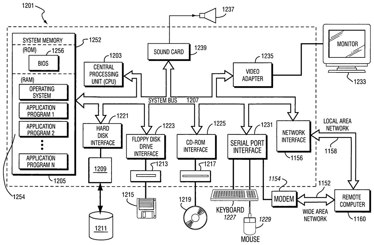
FIG. 14Billustrates one example emulation host system1201suitable for use with emulator1303. System1201includes a processing unit1203and a system memory1205. A system bus1207couples various system components including system memory1205to processing unit1203. System bus1207may be any of several types of bus structures including a memory bus or memory controller, a peripheral bus, and a local bus using any of a variety of bus architectures. System memory1207includes read only memory (ROM)1252and random access memory (RAM)1254. A basic input/output system (BIOS)1256, containing the basic routines that help to transfer information between elements within personal computer system1201, such as during start-up, is stored in the ROM1252. System1201further includes various drives and associated computer-readable media. A hard disk drive1209reads from and writes to a (typically fixed) magnetic hard disk1211. An additional (possibly optional) magnetic disk drive1213reads from and writes to a removable “floppy” or other magnetic disk1215. An optical disk drive1217reads from and, in some configurations, writes to a removable optical disk1219such as a CD ROM or other optical media. Hard disk drive1209, magnetic disk drive1213, and optical disk drive1217are connected to system bus1207by a hard disk drive interface1221, magnetic disk drive interface1223, and an optical drive interface1225, respectively. The drives and their associated computer-readable media provide nonvolatile storage of computer-readable instructions, data structures, program modules, game programs and other data for personal computer system1201. In other configurations, other types of computer-readable media that can store data that is accessible by a computer (e.g., magnetic cassettes, flash memory cards, digital video disks, random access memories (RAMs), read only memories (ROMs) and the like) may also be used.
A number of program modules including emulator1303may be stored on the hard disk1211, removable magnetic disk1215, optical disk1219and/or the ROM1252and/or the RAM1254of system memory1205. Such program modules may include an operating system providing graphics and sound APIs, one or more application programs, other program modules, program data and game data. A user may enter commands and information into personal computer system1201through input devices such as a keyboard1227, pointing device1229, microphones, joysticks, game controllers, satellite dishes, scanners, or the like. These and other input devices can be connected to processing unit1203through a serial port interface1231that is coupled to system bus1207, but may be connected by other interfaces, such as a parallel port, game port, Fire wire bus or a universal serial bus (USB). A monitor1233or other type of display device is also connected to system bus1207via an interface, such as a video adapter1235.
System1201may also include a modem1154or other network interface means for establishing communications over a network1152such as the Internet. Modem1154, which may be internal or external, is connected to system bus123via serial port interface1231. A network interface1156may also be provided for allowing system1201to communicate with a remote computing device1150(e.g., another system1201) via a local area network1158(or such communication may be via wide area network1152or other communications path such as dial-up or other communications means). System1201will typically include other peripheral output devices, such as printers and other standard peripheral devices.
In one example, video adapter1235may include a 3D graphics pipeline chip set providing fast 3D graphics rendering in response to 3D graphics commands issued based on a standard 3D graphics application programmer interface such as Microsoft's DirectX 7.0 or other version. A set of stereo loudspeakers1237is also connected to system bus1207via a sound generating interface such as a conventional “sound card” providing hardware and embedded software support for generating high quality stereophonic sound based on sound commands provided by bus1207. These hardware capabilities allow system1201to provide sufficient graphics and sound speed performance to play software stored in storage medium12.
An emulator1303used to provide some or all of the features of the video game system described above may also be provided with a graphic user interface (GUI) that simplifies or automates the selection of various options and screen modes for games run using the emulator. In one example, such an emulator1303may further include enhanced functionality as compared with the host platform for which the software was originally intended.
FIG. 14Cillustrates another example emulation host system1201′ suitable for use with emulator1303. The emulation host system inFIG. 14Cis generally configured along the lines of a personal digital assistant such as those available from Palm Inc., Handpsring, Inc. and Sony and running an operating system such as Windows CE, EPOC or PalmOS. Typically, such personal digital assistants provide capabilities for a diary/scheduler, to-do lists, phone/address books and the like. System1201′ includes a processing unit1503and memory1505. A system bus1507couples various system components including memory1505to processing unit1503. Memory1505includes read only memory (ROM) and random access memory (RAM). Memory1505may also include external memory in the form of memory cards or memory sticks inserted into a suitable port provided in the housing for the components of system1201′. A touch-sensitive display screen (e.g., a touch-sensitive liquid crystal display screen)1509is also connected to system bus1507via an interface1511. Inputs via touch-sensitive screen1509are typically made using a stylus. Other input devices1513such as pushbuttons, switches, pointing devices and the like are also connected to system bus1507via an interface1515. The input devices may also include external keyboards or game control devices (e.g., joystick, game controller). The input devices may be used as game controls (e.g., starting the game, character movement, character action, etc.) when system1201′ is used with emulator1303. Games may be written to memory1505using communication circuit1521which may take the form of a modem for downloading the game from the Internet, for example, or of a cradle (e.g., a USB cradle) for connecting system1201′ to a personal computer.
One or more speakers1517are connected to system bus1507via an audio interface1519to output sounds. A communication circuit1521is connected to system bus1507via a communications interface1523to permit communication with other devices. By way of illustration, communication circuit1521may, for example, be a modem and communications interface1523may be a serial port. Generally speaking, communication circuit1521may be configured for wired or wireless communication in accordance with any conventional communication protocol. A power supply1525provides power for the components of system1201′.
In addition, while digital camera accessory is shown as an add-on device to an existing game system, it is possible to incorporate some or all of the circuitry needed to implement the above-described operations in the portable game system itself.
Any patent documents mentioned above are hereby incorporated by reference into the present application.
Although the present invention has been described and illustrated in detail, this description is for illustrative purposes only and is not to be construed as limiting the present invention.
Claims
- A two-piece digital camera accessory for a display system comprising: a first unit comprising a first connector adapted for detachable connection to a connector of the display system and receiver circuitry for receiving wirelessly transmitted images;and a second unit comprising a connector adapted for detachable connection to a second connector of the first unit, an image sensor and transmitter circuitry for wirelessly transmitting images captured by the image sensor to the receiver circuitry of the first unit, wherein when the second unit is connected to the first unit and the first unit is connected to the display system, images captured by the image sensor are transmitted to the display system via a wired connection provided by the first and second connectors of the first unit and the connector of the second unit, and wherein when the second unit is detached from and located remotely with respect to the first unit and the first unit is connected to the display system, images captured by the image sensor are transmitted to the display system via the transmitter circuitry of the second unit and the receiver circuitry of the first unit.
- The digital camera accessory according to claim 1 , wherein the second unit and the first unit are detachably connected via an opening formed in the first unit into which the second unit is at least partially inserted.
- The digital camera accessory according to claim 1 , further comprising a memory in the first unit.
- The digital camera accessory according to claim 3 , wherein the memory stores a video game program.
- The digital camera accessory according to claim 1 , wherein the receiving circuitry of the first unit receives images transmitted from a device other than the second unit when the first unit is connected to the display system and the second unit is connected to the first unit.
- The digital camera accessory according to claim 1 , wherein the display system comprises a hand-held video game system.
- The digital camera accessory according to claim 1 , wherein the display system comprises a system configured to emulate a video game system.
- The digital camera accessory according to claim 1 , wherein the display system comprises a video game system.
- The digital camera accessory according to claim 1 , wherein the transmitter circuitry of the second unit compresses the captured images prior to transmission.
- The digital camera accessory according to claim 1 , wherein the transmitter circuitry of the second unit is operable to search for and select one of a plurality of channels for transmitting the captured images.
- The digital camera accessory according to claim 1 , wherein the second unit further comprises a microphone and the transmitter circuitry transmits sounds detected by the microphone.
- The digital camera accessory according to claim 11 , wherein the transmitter is controllable to transmit the sounds detected by the microphone, but not the video captured by the image sensor.
- The digital camera accessory according to claim 1 , wherein the transmitter transmits wirelessly within a frequency band comprising 2.4 to 2.488 GHz.
- The digital camera accessory according to claim 1 , wherein the transmitter transmits wirelessly using a frequency-hopping scheme.
- The digital camera accessory according to claim 1 , wherein the images captured by the image sensor comprise video images.
- The digital camera accessory according to claim 1 , wherein the first unit is detachably connected to the display system via an opening formed in the display system into which the first unit is at least partially inserted.
- A two-piece digital camera accessory for a display system comprising: a base unit detachably connected to the display system via an opening formed in a housing of the display system into which the base unit is at least partially inserted, the base unit comprising a first connector adapted for detachable connection to a connector of the display system and receiver circuitry for receiving wirelessly transmitted images;and a camera unit detachably connected to the base unit via an opening formed in a housing of the base unit into which the camera unit is at least partially inserted, the camera unit comprising a connector adapted for detachable connection to a second connector of the base unit, an image sensor and transmitter circuitry for wirelessly transmitting images captured by the image sensor, wherein when the camera unit is connected to the base unit and the base unit is connected to the display system, images captured by the image sensor are transmitted to the display system over a wired connection provided via the first and second connectors of the base unit and the connector of the camera unit, and wherein when the camera unit is detached from and located remotely with respect to the base unit and the base unit is connected to the display system, images captured by the image sensor are transmitted to the display system via the transmitter circuitry of the camera unit and the receiver circuitry of the base unit.
- A two-piece accessory for a display system comprising: a base unit comprising a first connector adapted for detachable connection to a connector of the display system and receiver circuitry for receiving wirelessly transmitted data;and a detecting unit comprising a connector for detachably connecting to a second connector of the base unit, a detector and transmitter circuitry for wirelessly transmitting data detected by the detector, wherein when the detecting unit is connected to the base unit and the base unit is connected to the display system, data detected by the detector is transmitted to the display system via a wired connection provided by the first and second connectors of the base unit and the connector of the detecting unit, and wherein when the detecting unit is detached from and located remotely with respect to the base unit and the base unit is connected to the display system, data detected by the detector is transmitted to the display system via the transmitter circuitry of the detecting unit and the receiver circuitry of the base unit.
Disclaimer: Data collected from the USPTO and may be malformed, incomplete, and/or otherwise inaccurate.