U.S. Pat. No. 7,963,849
INPUT ARRANGEMENT FOR VIDEO GAME TERMINAL
AssigneeJVL Corporation
Issue DateSeptember 13, 2006
Illustrative Figure
Abstract
A durable input arrangement for a video game terminal uses a joystick controller protected by a player actuating a control assembly. This assembly protects the joystick controller from abusive forces that would otherwise render the controller inoperative.
Description
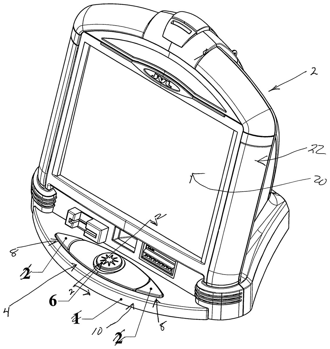
DETAILED DESCRIPTION OF THE PREFERRED EMBODIMENTS The video game terminal2shown inFIG. 1includes a control actuating arrangement4provided at the front of the terminal and at a base position. The particular video game terminal shown is for a counter top application although this control arrangement is suitable for upright video game terminals. The control actuating arrangement4includes a central player actuator control assembly6which is movable laterally through 360 degree movement. The control actuating arrangement4preferably includes left and right button actuators8positioned to opposite sides of the player actuator control assembly6. The player actuator control assembly6and the button actuators are secured in the cover10for the control actuating arrangement. This will be further described in relation toFIGS. 10 through 12. FIGS. 2 through 4are sectional views of the control actuating arrangement4taken along line2-2illustrating the joystick controller in different positions. The joystick controller40includes a short control shaft42rigidly connected to the ball actuator43. A circuit board44is provided at a lower position and senses the position of the ball actuator43. This joystick controller is a miniature joystick controller and is commonly available on the market. The miniature joystick controller is capable of more than 1,000,000 (one million) actuations and is based on resistive technology. This is the preferred type of joystick controller but other miniature joystick controllers could also be used. The circuit board44of the joystick controller40is mounted in a raised position above the bottom support plate50. This bottom support plate also includes a series of drain and air ventilation slots52to allow any liquid to pass through the base plate. These drain slots are provided adjacent the joystick controller and underneath the joystick controller. The joystick controller is fixed to the bottom support plate50and the short control shaft42extends upwardly into a joystick receiving recess36of the player actuator control assembly6. The player actuator control assembly6includes a top member30having a full ...
DETAILED DESCRIPTION OF THE PREFERRED EMBODIMENTS
The video game terminal2shown inFIG. 1includes a control actuating arrangement4provided at the front of the terminal and at a base position. The particular video game terminal shown is for a counter top application although this control arrangement is suitable for upright video game terminals.
The control actuating arrangement4includes a central player actuator control assembly6which is movable laterally through 360 degree movement. The control actuating arrangement4preferably includes left and right button actuators8positioned to opposite sides of the player actuator control assembly6. The player actuator control assembly6and the button actuators are secured in the cover10for the control actuating arrangement. This will be further described in relation toFIGS. 10 through 12.
FIGS. 2 through 4are sectional views of the control actuating arrangement4taken along line2-2illustrating the joystick controller in different positions. The joystick controller40includes a short control shaft42rigidly connected to the ball actuator43. A circuit board44is provided at a lower position and senses the position of the ball actuator43. This joystick controller is a miniature joystick controller and is commonly available on the market. The miniature joystick controller is capable of more than 1,000,000 (one million) actuations and is based on resistive technology. This is the preferred type of joystick controller but other miniature joystick controllers could also be used.
The circuit board44of the joystick controller40is mounted in a raised position above the bottom support plate50. This bottom support plate also includes a series of drain and air ventilation slots52to allow any liquid to pass through the base plate. These drain slots are provided adjacent the joystick controller and underneath the joystick controller. The joystick controller is fixed to the bottom support plate50and the short control shaft42extends upwardly into a joystick receiving recess36of the player actuator control assembly6.
The player actuator control assembly6includes a top member30having a full insert32in the center of the top member and exposed within the top surface of the player actuator control assembly. This insert includes a series of downwardly extending lock legs33which engage via a snap fit with the bottom member34. With this arrangement, the top member30is provided to the upper side of the cover10and the bottom member is provided below the cover10. The player actuator control assembly6is free to move within the oversized recess70provided in the top cover10. This allows the player actuator control assembly6to move laterally within the oversized recess while the player actuator control assembly is effectively trapped on the cover10.
FIG. 2also shows the support collar60having a large center recess62of a size to allow the joystick controller40to be located in this recess. The support collar60cooperates with the top cover10and the bottom member34of the player actuator6to support the player actuator6such that any substantial downward abusive force on the player actuator6is carried by the player actuator6and the collar60, as opposed to being carried by the joystick controller40. In the preferred embodiment, the player actuator6can exert some downward force on the joystick controller40to allow the player actuator control assembly6to also act as a button actuator.
Preferably, the joystick controller40also includes a light source which emits light upwardly through the player actuator control assembly6when the control actuator is activated for a particular game.
FIGS. 3 and 4demonstrate different positions of the joystick controller as the player actuator control assembly6is moved.
FIG. 2illustrates the player actuator control member in a central position, whereasFIG. 3shows the player actuator control assembly moved to an extreme position closer to the base of the touch screen, whereasFIG. 4shows the player actuator control assembly6moved to an extreme position away from the touch screen.
As can be seen, the control cover10and the bottom member34cooperate with the collar60to positively support the player actuator control assembly6.
Furthermore, it can be seen from reviewingFIGS. 2 through 4that the joystick receiving recess36is somewhat oversized such that lateral movement of the player actuator control assembly6affects pivoting of the control shaft42without tilting of the player actuator control assembly6. This particular action has been found to be more natural for a player where the effective movement of the player actuator control assembly6is generally in one plane and is not appreciably affected by any tilting.
The upper surface of the player actuator control assembly6is of size to comfortably receive at least two fingers of a player in a side by side relationship on the upper surface. Preferably, the top surface of the player actuator control assembly6is about two inches in diameter. A player will typically have two or three fingers on the player actuator control assembly6and move his hand and arm in controlling the position of the player actuator control assembly6. This type of action is more natural and does not require separate movement of the fingers or wrist of the player.
As shown inFIGS. 10 through 12, the cover member10receives the player actuator control assembly6as part of an assembly of the cover10and similarly, the button actuators8are also received and maintained in this assembly. Each of the button actuators8are received in button actuator pockets16of the cover10and are spring loaded. The assembled cover10for the control actuating arrangement4is shown inFIG. 10.
FIG. 7illustrates securement of the cover assembly10above the joystick controller40. The joystick controller is mounted on the printed circuit board45and this printed circuit board45cooperate with the button actuators8. The circuit board45as shown in the cross sectional views is at a raised position and is above the drain holes52shown inFIG. 9. The support collar60straddles the circuit board45and has the joystick controller40exposed within the large center port62. The cover assembly10can then be combined with the bottom support plate50and attached thereto by means of a series of screws or fasteners63.
Each of the button actuators includes a switch arrangement for completing a circuit with the circuit board45and preferably, this circuit board45also includes an LED47associated with each button actuator8. When the device is activated, for use with that particular game, these LED's are on and light is transmitted through the button actuators. The button actuators preferably include a translucent portion to allow the light to pass therethrough. This provides a further visual enhancement of the control actuating arrangement.
This particular arrangement has proven to be effective in both the assembly of the video game terminal and the durability of the video game terminal. Any liquid which is poured on the player actuator control assembly6is directed away from the joystick controller. As shown in the sectional view ofFIG. 4, the cover10includes a raised support surface18that serves to support the actuator control assembly6while also directing any poured liquid to flow off of the cover member10. Any liquid which passes through the oversized recess70in the cover member will strike the bottom member34and be directed outwardly of the joystick controller40. Furthermore, the raised position of the circuit board45and the drain holes provided about the joystick controller allow any liquid that enters through the cover to pass out the base of the video game terminal. Thus, the arrangement provides effective support and protects the joystick controller40and also serves to protect the joystick controller from liquid damage caused accidentally or deliberately.
Although various preferred embodiments of the present invention have been described herein in detail, it will be appreciated by those skilled in the art, that variations may be made thereto without departing from the spirit of the invention or the scope of the appended claims.
Claims
- In a video game terminal a control actuating arrangement comprising a miniature joystick controller mounted on a support member;a support collar mounted on said support member with a shaft actuator of said joystick controller exposed within said collar;a player actuator control assembly supported by said collar above said joystick controller and engaging an end of a control shaft of said joystick controller and causing pivoting movement of said control shaft in response to lateral movement of said player actuator control assembly;and wherein said player actuator control assembly is movable laterally through 360 degrees to enter player commands to said joy stick controller.
- In a video game terminal as claimed in claim 1 wherein said player actuator control assembly includes a top surface sized to receive in a side by side manner two or more fingers of a player to effect player input to said joystick controller via lateral movement of said player actuator control assembly.
- In a video game terminal as claimed in claim 2 wherein said player actuator control assembly is oversized relative to said joystick controller and protects said joystick controller from abusive forces.
- In a video game terminal as claimed in claim 3 wherein said player actuator control assembly covers said joystick controller and directs any liquid poured on said player actuator control assembly past said joystick controller.
- In a video game terminal as claimed in claim 3 wherein said joystick controller includes a button actuator controlled by downward movement of said control shaft and said player actuator control assembly accommodates limited downward movement thereof to actuate said button actuator of said joystick controller.
- In a video game terminal as claimed in claim 1 wherein said joystick controller includes an upwardly directed light source and said player actuator includes a translucent portion through which emitted light of said light source is transmitted.
- In a video game terminal as claimed in claim 6 wherein said light source is actuated for any games where said control actuating arrangement is activated.
Disclaimer: Data collected from the USPTO and may be malformed, incomplete, and/or otherwise inaccurate.