U.S. Pat. No. 7,959,511
INFORMATION PROCESSING DEVICE FOR CONTROLLING MOVEMENT OF A GAME CHARACTER BY USING A PLAYER IMAGE AND GAME CHARACTER MOVEMENT CONTROL METHOD
AssigneeSony Computer Entertainment Inc.
Issue DateDecember 21, 2006
Illustrative Figure
Abstract
An information processing system includes: area extraction means for extracting an area occupied by a player from the mirror moving picture containing a player; control means for generating a computer image containing a game character; and display control means for causing a display device to display a superimposed moving picture obtained by superimposing the mirror moving picture and the computer image. The control means moves the game character according to the area occupied by the player in the superimposed moving picture. Thus, in the information processing system using the player image acquired by a camera as the input interface, it is possible to improve the game entertainment.
Description
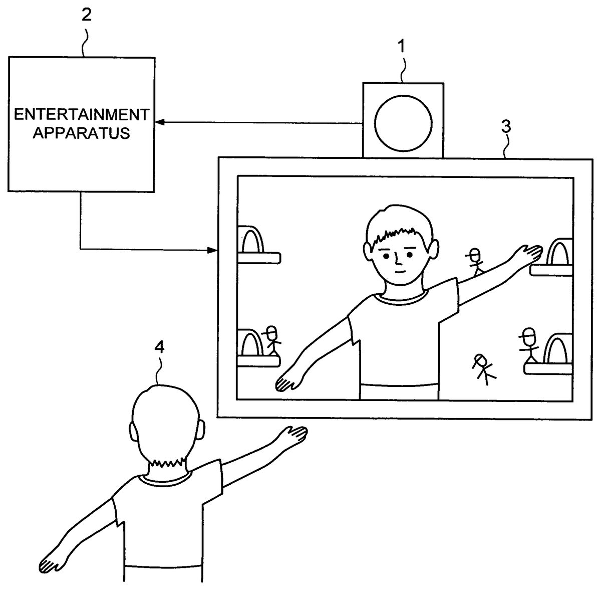
DESCRIPTION OF REFERENCE NUMERALS 1VIDEO CAMERA2ENTERTAINMENT APPARATUS3DISPLAY DEVICE101VIDEO IMAGE INPUT SECTION102IMAGE INVERTING SECTION103AREA EXTRACTING SECTION104MAIN CONTROLLER105CG GENERATOR106SUPERIMPOSED IMAGE GENERATOR107DISPLAY CONTROLLER PREFERRED EMBODIMENTS OF THE INVENTION Hereinafter, an exemplary embodiment of the present invention will be explained. FIG. 1shows an example of a configuration of an entertainment system relating to the present embodiment. This entertainment system takes an image of player4who is at a position facing a display device3, by using an analogue or digital video camera1. Entertainment apparatus2continuously captures the obtained moving image, and the computer image (CG) generated by the entertainment apparatus2and a mirrored moving image of the moving image captured from the video camera1are superimposed, to be displayed in real time on the display device3. Therefore, a motion of the player4is reflected on the superimposed image in real time, and the player can enjoy playing with this superimposed image. The entertainment apparatus2can generate the mirrored moving image by mirroring the moving image captured from the video camera1(right-left inversion of the image), but another method may also be available. For example, the mirroring may be performed on the video camera1. The entertainment apparatus2is implemented by an information processing device that forms required functions using a computer program. For example, as illustrated in the hardware configuration shown inFIG. 2, the entertainment apparatus2according to the present embodiment includes two buses, main bus B1and sub bus B2, to which multiple semiconductor devices, each having a specific function, are connected. Those buses B1and B2are connected to each other or disconnected from each other via a bus interface INT. The main bus B1is connected to a main CPU310that is a primary semiconductor device, a main memory311made up of RAM, a main DMAC (Direct Memory Access Controller)312, a MPEG (Moving Picture Experts Group) decoder (MDEC)313, and a Graphic Processing Unit (hereinafter, referred to as “GPU”)314that ...
DESCRIPTION OF REFERENCE NUMERALS
1VIDEO CAMERA2ENTERTAINMENT APPARATUS3DISPLAY DEVICE101VIDEO IMAGE INPUT SECTION102IMAGE INVERTING SECTION103AREA EXTRACTING SECTION104MAIN CONTROLLER105CG GENERATOR106SUPERIMPOSED IMAGE GENERATOR107DISPLAY CONTROLLER
PREFERRED EMBODIMENTS OF THE INVENTION
Hereinafter, an exemplary embodiment of the present invention will be explained.
FIG. 1shows an example of a configuration of an entertainment system relating to the present embodiment. This entertainment system takes an image of player4who is at a position facing a display device3, by using an analogue or digital video camera1. Entertainment apparatus2continuously captures the obtained moving image, and the computer image (CG) generated by the entertainment apparatus2and a mirrored moving image of the moving image captured from the video camera1are superimposed, to be displayed in real time on the display device3. Therefore, a motion of the player4is reflected on the superimposed image in real time, and the player can enjoy playing with this superimposed image. The entertainment apparatus2can generate the mirrored moving image by mirroring the moving image captured from the video camera1(right-left inversion of the image), but another method may also be available. For example, the mirroring may be performed on the video camera1.
The entertainment apparatus2is implemented by an information processing device that forms required functions using a computer program. For example, as illustrated in the hardware configuration shown inFIG. 2, the entertainment apparatus2according to the present embodiment includes two buses, main bus B1and sub bus B2, to which multiple semiconductor devices, each having a specific function, are connected. Those buses B1and B2are connected to each other or disconnected from each other via a bus interface INT.
The main bus B1is connected to a main CPU310that is a primary semiconductor device, a main memory311made up of RAM, a main DMAC (Direct Memory Access Controller)312, a MPEG (Moving Picture Experts Group) decoder (MDEC)313, and a Graphic Processing Unit (hereinafter, referred to as “GPU”)314that incorporates a frame memory315serving as a drawing memory. The GPU314is connected to a CRTC (CRT Controller)316that generates a video signal allowing data drawn in the frame memory315to be displayed on the display device3.
The main CPU310reads a startup program via the bus interface INT from the ROM323on the sub bus B2at the time of starting the computer, and executes the startup program to activate the operating system. In addition, the main CPU310controls the media drive327to read an application program and data from the media328mounted on this media drive327, and stores the read-in application program and data in the main memory311. Furthermore, the main CPU310applies geometric processing (coordinate value calculation processing) to represent shape, movement, and the like, of an object, on various data read from the media328, as in, for example, three-dimensional object data (coordinate values of vertices (representative points) of a polygon, etc.), made up of multiple basic graphics (polygons). Then, a display list is generated, which contains polygon definition information by the geometric processing. The polygon definition information includes as contents; a shape and a drawing position of the polygon used, and specifications of components constituting the polygon, such as type, color tone, and texture.
The GPU314is a semiconductor device having the functions of storing drawing context (drawing data containing polygon components), carrying out rendering processing (drawing processing) by reading necessary drawing context according to the display list notified from the main CPU310, and drawing polygons in the frame memory315. The frame memory315may also be used as a texture memory. Therefore, a pixel image in the frame memory315can be pasted as texture to a polygon to be drawn.
The main DMAC312is a semiconductor device having the functions of carrying out DMA transfer control over each of the circuits connected to the main bus B1, and also carrying out DMA transfer control over each of the circuits connected to the sub bus B2according to the condition of the bus interface INT. The MDEC313is a semiconductor device having the functions of operating in parallel with the main CPU310, and extending data having been compressed according to MPEG (Moving Picture Experts Group) format, JPEG (Joint Photographic Experts Group) format, or the like.
The sub bus B2is connected to sub CPU320made up of microprocessor and the like, sub memory321made of RAM, sub DMAC322, ROM323that stores a control program such as operating system, a sound processing-use semiconductor device (SPU: Sound Processing Unit)324that reads sound data accumulated in the sound memory325and outputs the data as audio output, a communication controller (ATM)326that sends information to and receives information from an external device via a network, not illustrated, and a media drive327to mount media328such as a CD-ROM and a DVD-ROM, and an input unit331.
The sub CPU320carries out various operations according to the control program stored in the ROM323. The sub DMAC322is a semiconductor device that carries out control such as DMA transfer over each of the circuits connected to the sub bus B2, only in the state in which the bus interface INT disconnects the main bus B1from the sub bus B2. The input unit331is provided with a connection terminal332through which an input signal from the operation device335is inputted, a connection terminal333through which an image signal from the video camera1is inputted, and a connection terminal334through which a sound signal is inputted from video camera1, or the like. It is to be noted that in the present embodiment, an explanation will be given regarding images only, and explanations regarding sound will be omitted for convenience.
The computer as thus configured operates as the entertainment apparatus2, when the main CPU310, the sub CPU320, and the GPU314read necessary computer programs from a recording medium such as the ROM323and the media328, and executes those computer programs.
FIG. 3is a functional block diagram of this entertainment apparatus2. In other words, a video image input section101, an image inverting section102, an area extracting section103, a main controller104, a CG generator105, a superimposed image generator106, and a display controller107are formed in the entertainment apparatus2.
The video image input section101captures a video image taken by the video camera1. The video image is a moving image, and the video image input section101continuously captures the images transferred from the video camera1.
The image inverting section102subjects the video image captured by the image input section101to mirroring, that is, right-left inversion process.FIG. 4Ashows one example of a video image200of a player, which is obtained by taking an image of the player and subjected to mirroring.FIG. 4Aincludes the mirrored image5of the player. Subsequent processing is performed on this mirrored video image. If the mirroring of the video image is set to be performed on the video camera1, it is possible to eliminate the image inverting section102.
The area extracting section103carries out processing to extract an area where the image of the player is placed from the video image inverted by the image inverting section102.
In the present embodiment, the area extracting section103stores in advance, as a reference image103a, one frame of the video image in which the image of the player is not placed. One example of the reference image103abeing associated withFIG. 4Ais shown inFIG. 4B. On the basis of a difference between the reference image and the video image, an area where the image of the player5is placed is extracted. The area where the image of the player5is placed, being associated withFIG. 4AandFIG. 4B, is shown inFIG. 4C.FIG. 4Cshows the area6that is obtained as a difference betweenFIG. 4AandFIG. 4B.
Therefore, in order to take an image in which the player is not contained, the entertainment apparatus2prompts the player to get out of the screen. In this condition, the area extracting section103extracts one frame of the video image that the image inverting section102has inverted, and then stores the extracted image as the reference image103a.
Specifically, before starting play on the entertainment apparatus2according to a directive from the player, the entertainment apparatus2makes a display prompting the player to get out of the screen, and extracts one frame of the video image after a lapse of a predetermined period of time. On this occasion, it is desirable that a countdown is displayed so as to allow the player to be aware of the time when the image is taken.
It is to be noted that a method to extract, from the video image, the area where the image of the player is placed is not limited to the above procedure. For example, it is also possible to detect a difference between a before-frame and an after-frame based on the motion of the player, or to extract an area where the image of the player is placed in the video image by the use of pattern recognition or the like.
The processing by the area extracting section103, to extract the area where the image of the player is placed, is performed continuously in real time. That is, along with the motion of the player, the area shown inFIG. 4Cvaries sequentially.
The main controller104conducts overall control of the entertainment system. For example, when the entertainment apparatus2is executing a game program, the main controller104decides a story for the game according to the program. In addition, when the main controller104decides the story, it may refer to a result of determination of a determining section103. Details of this procedure will be explained later. In other words, the entertainment apparatus2executes a program recorded in a recording medium such as a DVD-ROM or a CD-ROM, thereby configuring the functional block as shown inFIG. 3, and executes various processes of the present embodiment.
The CG generator105generates various computer images along with the game story line according to a directive from the main controller104. In the present embodiment, the CG generator105displays, on the screen, a character10as shown inFIG. 5according to a predetermined rule. The character10moves in the screen under control of the main controller104. At this time, it is desirable that the CG generator105changes the mode of how the character10is displayed, such as, for example, normal walking, climbing, or falling. In the present example, the character10is designed to represent a human being who is wearing a hat, but it is not limited to this example. The character may be an animal, a vehicle, or the like.
In addition, the CG generator105generates a computer image of an entrance that is a starting point for the character10and a computer image of an exit that is a goal for the character10. The entrance and the exit may be treated as fixed images. Furthermore, there may be more than one entrance and exit. In the present embodiment, two entrances are provided on the right edge of the screen and two exits are provided on the left edge of the screen. The two entrances are separately arranged one above the other, respectively, and the two exits are separately arranged one above the other, respectively, as well.
The superimposed image generator106superimposes the video image having been subjected to mirroring by the image inverting section102, and the computer image generated by the CG generator105. For example, the superimposed image generator106superimposes the video image200as shown inFIG. 4A, the character10as shown inFIG. 5, and the fixed images of the entrance21and the exit22, whereby the superimposed image400as shown inFIG. 6is generated. For ease of understanding, inFIG. 6, the background to the rear of the player5is omitted in the video image that has been subjected to mirroring.
The area where the image of the player is placed inFIG. 6corresponds to the area6extracted by the area extracting section103(seeFIG. 4C). In other words, the main controller104is able to figure out the area where the image of the player5is placed in real time.
The display controller107displays on the display device3the superimposed image generated by the superimposed image generator106. In other words, the player is allowed to conduct various operations in the entertainment system, while the player is viewing the superimposed image obtained by superimposing the mirrored moving image of himself or herself and the computer image.
Next, control of movement of the character10, which is carried out by the main controller104, will be explained. In the present embodiment, it is assumed that the character10moves along the area of the player extracted by the area extracting section103. Specifically, the character10moves assuming the area of the player as a route.
In other words, as shown inFIG. 6, the characters10appearing from the entrances21aand21bassume the area of the player5as a route, and move from the right side to the left side toward the exits22aand22b. In this situation, if a route does not exist, the character10may fall. Hereinafter, an explanation will be given assuming that the horizontal direction of the screen is the X-axis and the vertical direction of the screen is the Y-axis.
Here, since the main controller104is capable of recognizing the area of the player in real time, the main controller104controls the action of the character10as appropriate in response to a route change due to the motion of the player. As thus controlled, the character10looks as if it is moving along with the player.
On the other hand, by the player changing his or her own posture on the screen to define the route of the character10, a destination of each of the characters10is controlled in real time. For example, by getting onto the arm of the character10who has appeared from the entrance21a, it is possible to make a display in which the character moves while passing over the arm. If nothing is done about the character10who has appeared from the entrance21b, the character10ends up falling.
The main controller104may be able to further improve the game quality in the entertainment apparatus2by setting the exit22as a destination with respect to each character10according to the game scenario, making various types of characters appear, giving a bonus point in response to the player's control, and the like.
Next, specific examples of controlling the movement of the character10in the present embodiment will be explained. As shown inFIG. 7A, the character10basically proceeds in one direction, from right to left, in the horizontal direction. On the other hand, as for the vertical direction, if there is a route having a wall in front, the character10is controlled to proceed in the direction obliquely upward. If there is no route below, the character is controlled so as to go down. It is to be noted that if the character10falls on another route in mid-course while going down, the character10is controlled to move horizontally again. This may correspond to a motion of the player picking up the character10that is falling, a movement of the character10that is slipping down a slope, or the like.
Since the character10is required to be moved in real time, together with the player's area extraction process and the like, it is desirable that the control of the movement of the character10is performed in a simple process.
Therefore, in the present embodiment, conditions of the route in the foreside and in the downside of the character10are determined, thereby defining a subsequent moving direction. In other words, as shown inFIG. 7A, there are provided a forward detection area11in the foreside of the moving direction, and a downward detection area12in the downside. It is desirable that some parts of both the detection areas11and12may overlap the area where the character10occupies.
These detection areas11and12are areas to detect to what extent a part accepted as a route is contained in those areas. For example, each detection result may be represented as a ratio, such as 40%. This result indicates that a part accepted as a route occupies 40% of the detection area. This detection result can be obtained, for example, by dividing the detection areas11and12into a matrix with a predetermined size, determining whether or not each element of the matrix fits into the route, and then calculating a ratio of a part of the matrix corresponding to the route.
FIG. 7Bindicates an example in which the character10aand the character10bare passing along the route13. At this time, the character10ais detected as occupying around 50% of both the forward detection area11aand the downward detection area12aThe character10bis detected as occupying around 5% of the forward detection area11b, and 50% of the downward detection area12b.
On the basis of the detection results regarding the route in the detection areas11and12, the main controller104controls the movement of the character10according to the flow diagram as shown inFIG. 8. The main controller104allows multiple characters10to appear in the screen, and each of the characters10to move continuously and independently in real time according to the motion of the player, by repeatedly executing the process of the flow diagram as shown inFIG. 8for each character10.
Variable J is employed in the flow diagram above. In the case where there is no route below, that is, the player does not give a route to the character10, this variable J is used so that the character10starts falling after a lapse of a certain period of time, without the character10falling immediately.
The main controller104allows the character10to appear from any of the starting points (entrances21), and to conduct control as described below. It is to be noted that making the character10walk or run, according to the game scenario is also possible.
Firstly, the variable J is initialized to zero (S101).
Then, it is determined whether or not the current position is at a goal (exit22) (S102). As a result of the determination, if the character reaches the goal (S102: Y), a goal process is performed according to the game scenario (S103). Here, in the goal process, for example, the character10is erased from the screen, and the player can acquire a point being added according to a predetermined rule.
On the other hand, if the character10has not reached the goal yet (S102: N), it is determined whether or not there exists a route in front, on the basis of the detection result of the forward detection area11(S104). It is possible to determine whether or not there exists a route in front, for example, by the ratio of the route occupying the forward detection area11. By way of example, if the ratio is equal to or more than a predetermined value, for instance, 30%, it is possible to determine that a route exists in front.
As a result, if it is determined that a route exists in front (S104: Y), this route is assumed as an upward slope, the variable J is reset (S105), and climbing process is carried out (S106).
As shown inFIG. 9A, the climbing process allows the character10to move mostly in the upper direction with a larger Y-axis shift amount, and to move in the left direction with an X-axis shift amount being smaller than ordinary horizontal movement. The shift amount is set to a value suitable for the game scenario. Then, the process returns to step S102, and the subsequent process is repeated.
If it is determined that a route does not exist in front (S104: N), it is determined whether or not there exists a route below, on the basis of the detection result of the downward detection area12(S107). It is possible to determine whether or not there exists a route below, for example, by the ratio of the route occupying the downward detection area12. As a way of example, if the ratio is equal to or more than a predetermined value, for instance, 10%, it is determined that a route exists in front.
Consequently, if it is determined that a route exists below (S107: Y), this route is assumed as being horizontal, and the variable J is reset (S108).
It is further determined whether or not the ratio of the route occupying the downward detection area12is equal to or more than a predetermined value, for instance, 90% (S109). This is determined in order to know the condition of the character10, such as being buried in the ground as shown inFIG. 9B. In other words, if the ratio of the route occupying the downward detection area12is over a predetermined reference value, it is determined that the character is in a condition such as being buried in the route.
As a result, if the ratio of the route occupying the downward detection area12is less than the predetermined ratio (S109: N), the character10is moved in the left direction with respect to the X-axis, as a normal horizontal movement (S110). The shift amount is set to a value suitable for the game scenario. For example, if the character is running, the shift amount is set to be larger than the case where the character is walking. In the situation above, it is desirable to display the character10in such a manner as “walking”, “skipping”, and the like, according to the game scenario.
On the other hand, if the ratio of the route occupying the downward detection area12is equal to or more than a predetermined ratio (S109: Y), the character10is moved somewhat upwardly with respect to Y-axis, in addition to the above horizontal movement (S111). The character10is moved in this manner in order to avoid appearing to move while being buried in the route.
If it is determined that a route does not exist below (S107: N), 1 is added to J (S112). Then, it is determined whether or not J reaches a predetermined value (S113). That is, it is determined whether or not the condition that the route does not exist below, is still continuing.
As a result of the determination, if the value of J does not reach the predetermined value (S113: Y), the processing returns to step S102, and subsequent processing is repeated.
On the other hand, when J reaches the predetermined value (S113: N), a falling process is performed (S114). In the falling process, the character10is moved downwardly at a predetermined speed. At this time, it is desirable to display a falling motion.
It is to be noted that processing as below is performed for the character10after it has fallen. That is, if the character10goes out of the screen after falling, the character10is eliminated from a control target. In addition, detection of the downside by the downward detection area is continued during the falling motion (S115), and if a route is detected on the downside (S115: Y), the process returns to step S108and horizontal movement is restarted. For example, since the downside is not detected on the left end of the player's head, the character10starts falling. Then, upon falling on the shoulder part, a route on the downside is detected, and horizontal movement is restarted. Along the downward slope, falling and horizontal movement are repeated alternately in a short cycle, whereby the character10goes down stepwise.
It is to be noted that specific moving rules of the character10are not limited to the above example, and various methods can be employed. In addition, the route of the character10is not limited to the area where the image of the player is placed. For example, it is also possible to move the character10along an item such as a stick, operated by the player, that is regarded as the route.
Claims
- An information processing system comprising: an area extraction means that extracts an area occupied by a player, from a mirrored moving image based on a reference image;a control means that generates a computer image containing a game character;and a display control means that allows a display device to display a superimposed moving image obtained by superimposing the mirrored moving image and the computer image;wherein the control means moves the game character along the area occupied by the player in the superimposed moving image, the control means makes the game character fall, if there is no area occupied by the player below the game character, and the control means moves the game character obliquely upward in the moving direction of the game character, if there exists an area occupied by the player in front of the game character.
- The information processing system according to claim 1 , further comprising: a player moving image accepting means that accepts input of a player moving image obtained by taking images of the player by an image pickup device;and a mirrored moving image processing means that subjects the player moving image to mirroring.
- The information processing system according to claim 1 , wherein the display control means allows the display device to display an image prompting the player to get out of an image frame of the image pickup device, so as to obtain the reference image.
- The information processing system according to claim 1 , wherein the control means allows the game character to appear from one or a plurality of starting points provided on one side of a screen, and to move toward one or a plurality of goals provided on the other side of the screen.
- The information processing system according to claim 4 , wherein the control means determines whether or not there exists an area occupied by the player in front of the game character that is moving in a forward and below the game character.
- A non-transitory recording medium that records a program which can execute a game to move game characters by an information processing device that is connected to an image pickup device and a display device, the program causing the information processing device to perform functions comprising: an area extraction means that extracts an area occupied by a player, from a mirrored moving image based on a reference image;a control means that generates a computer image containing a game character;and a display control means that allows the display device to display a superimposed moving image obtained by superimposing the mirrored moving image and the computer image;wherein the control means moves the game character along the area occupied by the player in the superimposed moving image, the control means makes the game character fall, if there is no area occupied by the player below the game character, and the control means moves the game character obliquely upward in the moving direction of the game character, if there exists an area occupied by the player in front of the game character.
- The non-transitory recording medium according to claim 6 , wherein the program causes the information processing device to perform functions comprising: a player moving image accepting means that accepts input of a player moving image obtained by taking images of the player by the image pickup device;and a mirrored moving image processing means that subjects the player moving image to mirroring.
- The non-transitory recording medium according to claim 6 , wherein the display control means allows the display device to display an image prompting the player to get out of an image frame of the image pickup device, so as to obtain the reference image.
- The non-transitory recording medium according to claim 6 , wherein the control means allows the game character to appear from one or a plurality of starting points provided on one side of a screen, and to move toward one or a plurality of goals provided on the other side of the screen.
- The non-transitory recording medium according to claim 9 , wherein the control means determines whether or not an area occupied by the player exists in front of the game character that is moving in a forward and below the game character.
- A game character movement control method in an information processing device that is connected to an image pickup device and a display device, comprising: an area extraction process that extracts an area occupied by a player, from a mirrored moving image based on a reference image;a control process that generates a computer image containing a game character;and a moving control process that allows the display device to display a superimposed moving image obtained by superimposing the mirrored moving image and the computer image, and moves the game character, regarding an area occupied by the player in the superimposed moving image as a route, wherein the control process makes the game character fall, if there is no area occupied by the player below the game character, and moves the game character obliquely upward in the moving direction of the game character, if there exists an area occupied by the player in front of the game character.
- An information processing system comprising: an area extraction means that extracts an area occupied by a player, from a mirrored moving image based on a reference image;a control means that generates a computer image containing a game character;and a display control means that allows a display device to display a superimposed moving image obtained by superimposing the mirrored moving image and the computer image;wherein the control means moves the game character along the area occupied by the player in the superimposed moving image, and further comprising detection means to detect an overlap area between a detection area provided for the game character and the area occupied by the player, wherein when the detection means detects an area where a ratio of overlap is greater than a predetermined value, the control means determines that there is a route in the direction of the overlap area and moves the game character along the route.
- The information processing system according to claim 12 , wherein at least more than two detection areas are provided for the game character.
- A non-transitory recording medium that records a program which can execute a game to move game characters by an information processing device that is connected to an image pickup device and a display device, the program causing the information processing device to perform functions comprising: an area extraction means that extracts an area occupied by a player, from a mirrored moving image based on a reference image;a control means that generates a computer image containing a game character;and a display control means that allows the display device to display a superimposed moving image obtained by superimposing the mirrored moving image and the computer image;wherein the control means moves the game character along the area occupied by the player in the superimposed moving image, and further comprising detection means to detect an overlap area between a detection area provided for the game character and an area occupied by the player, wherein when the detection means detects an area where a ratio of overlap is greater than a predetermined value, the control means determines that there is a route in the direction of the overlap area and moves the game character along the route.
- The non-transitory recording medium according to claim 14 , wherein at least more than two detection areas are provided for the game character.
Disclaimer: Data collected from the USPTO and may be malformed, incomplete, and/or otherwise inaccurate.