U.S. Pat. No. 7,932,908
APPARATUS SYSTEMS, AND THE METHODS FOR STIMULATING MOVEMENT OF A BALL IN RESPONSE TO A SIGNAL GENERATED IN AN INPUT DEVICE MOVED BY A GAME PLAYER
AssigneeSSD Co Ltd
Issue DateJune 4, 2001
Illustrative Figure
Abstract
A sensing baseball game apparatus (10) has a game machine (12) connected to a television monitor (18). A bat input device (32) is provided with an acceleration sensor. An acceleration signal is transmitted by an infrared-ray LED (34) to an infrared-ray receiving part of the game machine (12) whereby the game machine (12) determines a moving speed of the bat input device (32) to calculate a moving parameter of a ball to be batted. Accordingly, a batted ball is moved in the game scene according to the parameter.
Description
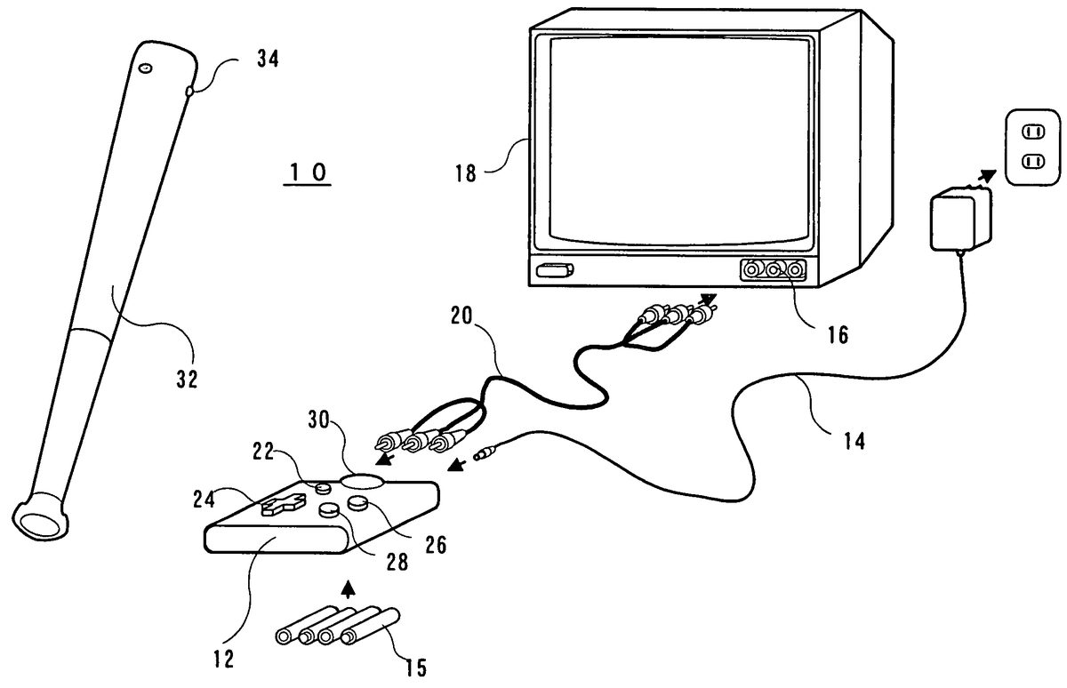
BEST MODE FOR CARRYING OUT THE INVENTION A sensing baseball game apparatus10as an example of the present invention shown inFIG. 1includes a game machine12. This game machine12is supplied with a direct current power through an AC/DC adapter14. This, however, may be replaced with a battery15. The game machine12is further connected to an AV terminal16of a television monitor18through an AV cable20. The game machine12includes a housing having, thereon, a power switch22and three operation keys24,26and28. The direction key24, e.g. a cross key, is used, for example, to instruct a direction of a game character on a display screen of the television monitor18or move a cursor for menu selection. The decision key26is used to determine an input to the game machine12while the cancel key28is used to cancel an input to the game machine12. The game machine12is furthermore provided with an infrared-ray receiver30. The infrared-ray receiving part30is to receive an infrared-ray signal from an infrared-ray LED42on the bat input device32. The bat input device32is formed, for example, of plastic, and has a shape, size or weight analogous to a bat for use in actual baseball. This device is to be moved in the three-dimensional space by game player's actual swing. To play a sensing baseball game of this embodiment, the game player holds the bat input device32at a grip part and swings the bat input device32just like in actual baseball. By detecting an acceleration or rotation speed of the bat input device32at that time, the game machine12causes a change in a game image being displayed on the television monitor18. It is noted that the shape, size or weight of the bat input device32may be desirably modified for safety in consideration of it as a toy. However, the bat input device32has an interior made hollow in at least one part thereof, to incorporate therein an ...
BEST MODE FOR CARRYING OUT THE INVENTION
A sensing baseball game apparatus10as an example of the present invention shown inFIG. 1includes a game machine12. This game machine12is supplied with a direct current power through an AC/DC adapter14. This, however, may be replaced with a battery15. The game machine12is further connected to an AV terminal16of a television monitor18through an AV cable20. The game machine12includes a housing having, thereon, a power switch22and three operation keys24,26and28. The direction key24, e.g. a cross key, is used, for example, to instruct a direction of a game character on a display screen of the television monitor18or move a cursor for menu selection. The decision key26is used to determine an input to the game machine12while the cancel key28is used to cancel an input to the game machine12. The game machine12is furthermore provided with an infrared-ray receiver30. The infrared-ray receiving part30is to receive an infrared-ray signal from an infrared-ray LED42on the bat input device32.
The bat input device32is formed, for example, of plastic, and has a shape, size or weight analogous to a bat for use in actual baseball. This device is to be moved in the three-dimensional space by game player's actual swing. To play a sensing baseball game of this embodiment, the game player holds the bat input device32at a grip part and swings the bat input device32just like in actual baseball. By detecting an acceleration or rotation speed of the bat input device32at that time, the game machine12causes a change in a game image being displayed on the television monitor18.
It is noted that the shape, size or weight of the bat input device32may be desirably modified for safety in consideration of it as a toy. However, the bat input device32has an interior made hollow in at least one part thereof, to incorporate therein an acceleration switch, an acceleration sensor, etc. hereinafter referred.
In the sensing baseball game apparatus10ofFIG. 1, a game scene for example shown inFIG. 2is displayed on a screen of the television monitor18. The game screen includes a still image (text screen) showing a baseball ground displaying therein a pitcher character a41and other athlete characters a42. The pitcher character a41at least is displayed as a moving-image character (sprite). Instead, all the athlete characters on the screen may be displayed as sprite images.
In the game screen, a pitcher character a41pitches a ball character (hereinafter, may be referred to merely as “ball”) a43toward a home base character a48. The ball a43is also a sprite image that moves toward the home base character a48in accordance with a pitch action by the pitcher a41. The game player swings the bat input device32(FIG. 1) in a manner of hitting the ball a43. Note that the home base character a48is displayed as a text screen.
In the game machine12, when the player actually swings the bat input device32, a signal from the acceleration switch or acceleration sensor (hereinafter referred) is transmitted as an infrared-ray signal from the infrared-ray LED34to the infrared-ray receiver30. The ball a43is moved toward the pitcher a41or another athlete a42as if the ball a43was hit back by the bat, according to timing the bat input device32reaches a predetermined moving speed and a position of the ball a43on the screen. It is discriminated, according to a position where the ball a43has moved to, whether gained is a hit (home run, three-base hit, two-base hit, one-base hit), foul, fly ball, grounder, out, safe or the like. However, where there is a deviation between the position of the bat when the bat input device32is swung and the position of the ball a43on the screen, a missed swing for example is recognized.
As can be understood from a reference toFIG. 2, on the game screen, a ball speed display part a44, score display part a45, count display part a46and runner display part a47are further provided as required. The ball speed display part a44is to display a speed of the ball a43pitched by the pitcher character a41. This, however, displays a ball speed in accordance with a moving speed of a ball input device64(FIG. 9) pitched by the game player, in another embodiment hereinafter described. The score display part a45displays game score in what innings in top or bottom. The count display part a46is to display strike count, ball count and out count. The runner display part a47is to display the runners now being on the bases.
FIG. 3is a block diagram of the sensing baseball game apparatus10ofFIG. 1. On the bat input device32, the carrier (carrier wave) generated from a carrier generating circuit36is gated by an acceleration switch38. Consequently, when the acceleration upon swinging the bat input device32is greater than a predetermined level, a carrier is supplied to the infrared-ray LED34to drive the same. The acceleration switch38may use a type which is turned on to output a signal when the acceleration of the bat input device32becomes greater than a certain level. For example, the acceleration switch may accommodate a weight for displacement within a cylindrical housing wherein the weight is elastically biased by a spring. When the input device is swung, a centrifugal force acts upon and displaces the weight against the spring, turning on the switch. In this case, by properly providing an elastic force to the spring, it is possible to properly set whether to output an on signal at what degree of an acceleration applied.
An infrared-ray receiver30is provided on the game machine12to receive an infrared-ray signal from the infrared-ray LED34. The infrared-ray light receiver30demodulates a received infrared-ray signal and inputs it as an acceleration-correlated signal to the game processor40.
Although the game processor40may use an arbitrary kind of processor, this embodiment uses a high-speed processor having been developed and already applied for a patent by the present applicant. This high-speed processor is concretely disclosed, for example, in Japanese Patent Laid-open No. 307790/1998 [G06F 13/36, 15/78] and the corresponding U.S. patent application Ser. No. 09/019,277.
The game processor40, although not shown, includes various processors such as a CPU, a graphic processor, a sound processor and a DMA processor. This also includes an A/D converter used in fetching analog signals, and an input/output control circuit to receive input signals such as key operation signal and infrared-ray signals and supplies output signals to an external apparatus. Consequently, the demodulation signal from the infrared-ray receiving part30and the input signal from the operation key24-28are delivered to the CPU through the input/output control circuit. The CPU executes a required operation according to an input signal and supplies a result thereof to other processors. Accordingly, the graphic processor and sound processor execute an image process and sound process in accordance with the operation result.
The game processor40is provided with an internal memory42. The internal memory42includes a ROM or RAM (SRAM and/or DRAM). The RAM is utilized as a in temporary memory, a working memory or a register area and a flag area. Incidentally, an external memory (ROM and/or RAM) is connected to the game processor40through an external bus. The external memory44is previously set up with a game program.
The game processor40executes, utilizing the above processors, operation and graphic and sound processes according to an input signal from the infrared-ray receiver30and operation key24-28, and outputs video and audio signals. The video signal is a combination of a text screen shown inFIG. 2and a sprite image. These video and audio signals are supplied to the television monitor18through the AV cable20and AV terminal16. Consequently, a game image is displayed together with required sound (sound effect, game music) as shown inFIG. 2on a screen of the television monitor18.
With reference toFIG. 4toFIG. 6, explanation is concretely made on the bat input device32as one feature of this embodiment.FIG. 4shows a tip portion of the bat input device32together with its interior structure. In the interior of the tip of the bat input device32, a printed circuit board48is fixedly attached parallel in plane with a tip surface46by a boss50vertically standing from an inner surface of the tip surface46. The printed circuit board48has a piezoelectric buzzer52mounted in one surface, and on the other surface an interconnect pattern constituting an electric circuit shown inFIG. 5including the piezoelectric buzzer52. The infrared-ray LED34is mounted on the printed circuit board48and placed facing to a light transmission part formed in a tip-periphery side surface of the bat input device32. Accordingly, the infrared-ray signal from the infrared-ray LED34is outputted through the light transmission part and then received by the infrared-ray receiving part30provided on the game machine12, as was explained before.
The piezoelectric buzzer52is a piezoelectric ceramic plate52formed, for example, barium titanate or PZT having electrodes52band52crespectively formed on the both main surfaces thereof, as well known or as shown inFIG. 5. This embodiment utilizes a piezoelectric buzzer52as an acceleration sensor. That is, in this embodiment the acceleration-correlated signal generating means utilizes an acceleration sensor in place of the acceleration switch explained before with reference toFIG. 3.
More specifically, the piezoelectric buzzer52is attached parallel, in plane, with the tip surface46of the bat input device32. When the bat input device32is swung by the game player, the tip is acted upon by a strongest centrifugal force. Consequently, the piezoelectric plate52aof piezoelectric buzzer52is deformed by the centrifugal force, causing a potential difference between the opposite main surfaces of the piezoelectric plate52aproportionally to the deformation. The potential difference varies depending upon a stress (centrifugal force) received by the piezoelectric plate52a. If the stress is great, the strain, or potential difference, is great while if the stress is small, the strain, or potential difference, is small. In other words, the potential difference caused on the piezoelectric buzzer52varies depending upon a speed or intensity of swing of the bat input device32by the player. Accordingly, it is possible for this embodiment to utilize the piezoelectric buzzer52as an acceleration sensor.
The potential difference caused on the piezoelectric buzzer52is provided to a base of a transistor54. Consequently, the transistor54conducts at a conductivity in accordance with a magnitude of the potential difference. Those of the piezoelectric buzzer52shown at a left inFIG. 5, the accompanying circuit elements and the transistor54are referred to as an acceleration sensor56.
The collector output of the transistor54is inputted to a modulation pulse generating circuit58. The modulation pulse generating circuit58includes a capacitor59. The capacitor59is charged with electric charges in amount corresponding to the conductivity of the transistor54. That is, because the transistor54and capacitor59form a common current route, the conductivity of the transistor54when great increases the current flowing through the transistor54and decreasing the charge current flowing to the capacity59. Conversely when the conductivity of the transistor54is small, the current flowing through the transistor54decreases and the charge current flowing in the capacitor59increases. The charge voltage on the capacitor59is discriminated in level by a transistor60. Consequently, the transistor60at an emitter outputs a pulse having a pulse width depending upon a magnitude of the charge voltage to the capacity59.
The modulation pulse from the modulation pulse generating circuit58is applied to a carrier generating circuit62. The carrier generating circuit62generates predetermined frequency of a carrier (carrier wave). Consequently, the carrier generating circuit62has an output as a signal having the carrier modulated by a modulation pulse. The modulated signal acts to operate a switching transistor63. In response, the infrared-ray LED34flickers according to the modulated signal, and the infrared-ray LED34outputs an infrared-ray signal in accordance with that signal.
It is assumed with reference toFIG. 6at the bat input device has an acceleration varying as shown inFIG. 6(A). Following the acceleration change, a voltage signal as shown inFIG. 6(B)is outputted from the piezoelectric buzzer52. When the voltage signal exceeds a determination level as determined by the transistor54, the transistor54is placed in conduction, i.e. gate is opened. As was explained before, a modulation pulse having a pulse width nearly in reverse proportional to a magnitude of the acceleration, or a voltage signal from the piezoelectric buzzer52, is outputted from the modulation pulse generating circuit58, as shown inFIG. 6(D). Although the carrier generating circuit62generates a carrier as shown inFIG. 6(E), the carrier is modulated by the modulation pulse. Accordingly, an infrared-ray signal as shown inFIG. 6(F)is outputted from the infrared-ray LED34.
The infrared-ray receiver30(FIG. 3) provided on the game machine12receives such an infrared-ray signal and demodulate it to obtain a modulated signal as shown inFIG. 6(G). This demodulated signal is inputted to the game processor40through the input/output control circuit (not shown). Consequently, the game processor40calculates a speed of a swing of the bat input device32by the game player, i.e. a rotation speed of the bat input device30, on the basis of the demodulated signal ofFIG. 6(G).
FIG. 7is a flowchart for calculating a rotation speed. This flowchart shows an interrupt operation to be executed each time a front edge of a demodulated signal comes as shown inFIG. 6(G). When a demodulated signal front edge is detected, the CPU (not shown) included in the game processor40reads in a count value (timer value) of a not-shown timer circuit. Next, the CPU resets the timer circuit in response to a demodulated signal rear edge. Consequently, the CPU knows a timer value between the front and rear edges of a demodulated signal pulse. Accordingly, a reciprocal of the timer value (1/timer value) is determined as a moving or rotation speed of the at input device32.
The moving or rotation speed of the bat input device32thus determined is reflected in the movement of a batted ball, thereby causing a change in a distance or direction of the ball a43(FIG. 2) in accordance with a swing speed of the bat input device32.
Referring toFIG. 8, in the first step S1the game processor40(FIG. 3) causes a change in the shape of a pitcher character a41and the shape and position of a ball a43such that, on the screen, the pitcher character a41makes pitching to move the ball in accordance therewith. At this time, because the game processor40naturally displays a text screen as well, a game scene shown inFIG. 2is displayed on the television monitor18. Such a game image is generated by the graphic processor included in the game processor40.
In the next step S2, the game processor40resets the rotation speed value retained in a rotation speed register (not shown) formed in the internal memory42(FIG. 3).
Thereafter, the game processor40in step S3takes in a rotation speed determined as inFIG. 7and determines whether the taken rotation speed is “0” or not, i.e. whether the game player has swung the bat input device32or not. If the game player has swung the bat input device32, the rotation speed is not “0” and the process proceeds to the next step S4. When the rotation speed is “0”, the process proceeds to step S6.
In the step S4, the game processor40determines whether the rotation speed taken in the step S3is smaller than the value retained in the rotation speed register (rotation speedretained value) or not. In a pitch action using the ball input device64, the moving speed usually is low in the beginning of pitch action and gradually increased. Consequently, the determination “NO” in the step S14means the moving speed has not reached a peak. In this case, the retained value of the moving-speed register in this step S15is updated with a moving speed at that time, and then the process returns to the step S12. The determination “YES” in the step S14means that a peak of the moving speed has been detected. In this case, process proceeds to step S16.
In the step S16, the parameters of ball change degree, moving speed, moving direction, etc. are determined on the basis of each-axis rotation speed, each-axis moving speed, time to the moving-speed peak, etc.
More specifically, a rotation speed is determined on the basis of the moving speeds on each axis sandwiching the origin. For example, if there is a difference between the moving speeds z1and z2in the z-axis direction, it can be considered that the ball input device64is rotating about the x-axis. Similarly, if there is a difference between the moving speeds x1and x2in the x-axis direction, the ball input device64can be considered rotating about the y-axis. If there is a difference between moving speeds y1and y2in the y-axis direction, the ball input device64can be considered rotating about the z-axis. Consequently, an x-axis rotation speed is determined by “z1−z2”, a y-axis rotation speed by “x1−x2”, and a z-axis rotation speed by “y1−y2”. Furthermore, the moving speeds in the axial directions are retained in the moving-speed register. Also, a peak-reaching time can be determined by making reference to count value of a timer provided in the game processor40.
According to the parameters determined in the step S16, the game processor40moves the ball a43as a sprite image in the game scene of the television monitor18(FIG. 9). It is needless to say that the real-time position of the ball a43can be computed by integrating the moving speeds.
The use way and the operation accompanied therewith of the bat input device32in theFIG. 9embodiment are similar to those ofFIG. 1embodiment. Accordingly, in theFIG. 9embodiment, one game player is allowed to make a pitch action using the ball input device64while the other game player swings the bat input device32, thereby enjoying a competition-type sensing baseball game.
Referring toFIG. 13, a sensing table-tennis game apparatus100as another embodiment of the invention includes a game machine12, a television monitor18and an AV cable20for connecting between them, similarly to the sensing baseball game apparatus10explained above. The game machine12is further provided with a power switch22, a select key24′ and a decision key26, and an infrared-ray receiver30′. An external memory44is installed with a program for a sensing table-tennis game.
This embodiment uses two racket input devices80. The racket input device80has an infrared-ray LED34and a serve switch82. The switch82is operated when putting a serve ball. The infrared-ray signal from the infrared-ray LED34is received by the infrared-ray receiver30′ of the game machine12. As explained later, the racket input device80has a piezoelectric buzzer or acceleration sensor, similarly to the foregoing input device32and64. The game machine12receives an acceleration signal from the acceleration sensor, to cause a change in the ball a43in the game scene shown inFIG. 14.
Referring toFIG. 14, the game screen displayed on the television monitor18of the sensing table-tennis game apparatus100, when in a competition-type game, is split into upper-and-lower two screen portions. The upper screen portion displays an image as viewed from one game player while the lower screen portion displays an image as viewed from the other game player. The upper and lower screens each display a ball a43and athlete characters a491and a492as sprite images, and a net character a50and a ping-pong table character a51as text screen. Score indicator areas a521and a522are formed, respectively, on the upper and lower portions to indicate score of the relevant game players.
Referring toFIG. 15, the racket input device80has an acceleration sensor56similar to that of the foregoing embodiment. The acceleration sensor56outputs an acceleration-correlated signal to an MCU84. The MCU, e.g. single-chip microcontroller, converts the acceleration-correlated voltage signal inputted from the acceleration sensor into a digital signal and digital-modulates to be supplied to an infrared-ray LED34. The digital-modulated infrared-ray signals from the respective infrared-ray LEDs34of the two racket input devices80are received by the infrared-ray receiver30′ of the game machine12, and then digital-demodulated and inputted to the game processor40. The digital signal in an amount of 1 bit is transmitted as “1” or “0” depending upon on or off of a switch82. Consequently, the game processor40checks the bit, thereby determining which game player has put a serve ball.
In the sensing table-tennis game apparatus100, in brief the game machine12, or game processor40, receives acceleration data contained in the infrared-ray signals from the two racket input devices80and determines a moving speed of the racket input device80. When the moving speed reaches a peak, the game processor40determines a parameter of ball a43movement to move the ball a43in the game scene according to the parameter.
The racket input device80includes a grip part86and a ball-hitting part88extending from a tip of the grip, as shown inFIG. 16. These grip part86and ball-hitting part88are integrally formed, for example, by a two-split plastic housing. Bosses90and92are formed in an interior of the ball-hitting part88of the plastic housing of the racket input device80, to bond together the two-split housing parts. The boss90is further fixed with a piezoelectric buzzer52serving as an acceleration sensor56(FIG. 15). In the lower housing, a boss94is further formed to mount a printed circuit board96on the boss94. A switch82and MCU84shown inFIG. 15is attached on the printed board96. In the lower housing, a boss98is further formed to fixed thereon an LED board100. On the LED board100, an infrared-ray LED34is attached. Incidentally, electrical connection is provided between the piezoelectric buzzer, or acceleration sensor56, the MCU84, the switch82and the infrared-ray LED34, as shown inFIG. 15.
Referring toFIG. 17, explanation is made on the operation that a moving speed of the racket input device80is detected to hit back the ball a43(FIG. 14). In the first step S21, the game processor40resets a moving speed value for the racket input device80retained in the moving speed register (not shown) formed in the internal memory42(FIG. 15).
Thereafter, the game processor40in step S22fetches a moving speed as determined inFIG. 7and determines whether the fetched moving speed is “0” or not, i.e. whether the game player has swung the racket input device80or not. If the game player has swung the racket input device80, the moving speed is not “0” and hence the process proceeds to the next step S23. When the moving speed is “0”, the process proceeds to step S25.
In the step S23, the game processor40determines whether the fetched moving speed is smaller than the value retained in the moving speed register (moving speed<retained value) or not. In the beginning of swinging of the racket input device80, the moving speed gradually increases, and accordingly “NO” is determined in this step S23. Accordingly, the game processor40replaces the retained value in the moving speed register with a moving speed at that time. That is, the moving speed is updated of its retained value.
In the advance of swing of the racket input device80, the moving speed soon reaches a peak and then gradually decreases. It can be determined in the step S23whether the moving speed of the racket input device80has reached a peak or not.
Subsequently, the game processor40determines whether the ball a43(FIG. 14) has reached a ball-return limit position or not. This determination can be made by detecting whether the ball a43in depth position (known by the CPU) has moved to a position assumed as a ball-return limit or not.
The fact of determination “YES” in the step S23before the ball a43has reached the ball-return limit position means that no peak of the moving speed has detected before reaching the ball-return limit position after hitting back of the ball a43or hitting a serve ball a43by the opponent player. In other words, this means a disagreement between the timing of swinging the racket input device80by the game player and the timing of movement of the ball a43, i.e. the swing was after the ball a43has reached the ball-return limit position. In this case, the game processor40determines as “missed swing”. However, the moving speed remaining “0” in the step S22means that the racket input device80has not been swung. In this case, the game processor40will determine as out ball or safe ball, by whether the ball a43reach position is on the ping-pong table a51(FIG. 14) or not.
The steps S22to S24are repeated until the ball a43has reached the ball-return limit position. In this process, if “YES” is determined in step S23, then it means that the moving speed due to swing of the racket input device80has reached a peak. In this case, in step S26game processor40determines the parameters of a moving speed in a reverse direction, a direction and the like of the ball a43hit back by the racket. The ball a43is moved according to the parameters thus determined.
According to theFIG. 13embodiment, when the game player swings the racket input device80to a ball movement in the game scene, a moving speed of the input device80is detected to hit back the ball according to the speed and timing thereof, thereby moving the ball as a hit ball in the game scene. In accordance with a position to which the ball moves, etc., determination is made as out ball or safe ball just like in a usual table-tennis game. Accordingly, in this embodiment, the game player is allowed to swing the racket input device80, thereby enjoying a realistic feeling that could not have been experienced in the conventional television game.
Incidentally, theFIG. 13embodiment showed the competition-type sensing table-tennis game apparatus using to racket input devices80. However, it is possible to enjoy a “single play” using only one racket input device80. The game screen in this case displays, in the entire screen, one athlete a49, one ball a43, one net a50and one ping-pong table, as shown inFIG. 18. However, background images such as spectator seats may be displayed if required. In the case of a “single play”, hitting back by the athlete a49will be under control of the game processor a40. Incidentally, although only one acceleration sensor was provided in the racket input device80, the provision of four or at least three acceleration sensors enables detection of an X-axis (left and right) direction and a Y-axis (forward and backward) direction of the ball-hitting part88. This will achieve higher level of control, thus making possible to make the game more interesting.
The foregoing embodiments concretely explained on the baseball and table-tennis games. However, this invention is also applicable to desired ball games that an input device to be moved or displaced in the three-dimensional space by the game player is used to cause a change in the ball character on the game scene according to an acceleration (moving speed or displacing speed) of the input device.
Although the present invention has been described and illustrated in detail, it is clearly understood that the same is by way of illustration and example only and is not to be taken by way of limitation, the spirit and scope of the present invention being limited only by the terms of the appended claims.
Claims
- A ball game apparatus for playing a ball game, said ball game apparatus being configured to operate with a screen of a display device, said ball game apparatus comprising: an input device including a handle to be moved in a three-dimensional space by a game player, to produce a movement for simulating an attempted interception of a ball;a first signal-generator incorporated in said input device to output an acceleration correlated signal according to an acceleration upon moving said input device in the three-dimensional space to produce said movement for simulating an attempted interception of a ball, said acceleration correlated signal indicating a plurality of different non-zero acceleration values;a second signal-generator incorporated in said input device to output a second signal in response to said accelerated correlation signal;and a game processor for displaying a ball character on said screen of said display device, receiving said second signal, and determining, based on said second signal and a moving timing of said ball character that is a position of said ball character in a depth direction in said screen, a moving direction of said ball character as a parameter for a movement of the ball character after a hit.
- The game apparatus according to claim 1 , wherein said game processor determines a moving direction of said ball character by further taking an approaching course of said ball character into account.
- The game apparatus according to claim 1 , wherein said game processor determines a moving speed of said ball character in accordance with a level of said acceleration.
- The game apparatus according to claim 1 , wherein said first signal-generator includes a piezoelectric buzzer.
- The game apparatus according to claim 1 , wherein said game processor detects a timing that said acceleration reaches a peak value, and determines based on said timing and said moving timing of said ball character said moving direction of said ball character.
- The game apparatus according to claim 1 , wherein said game processor detects a timing that said acceleration reaches a predetermined value, and determines based on said timing and said moving timing of said ball said moving direction of said ball character.
- The game apparatus according to claim 1 , wherein said second signal-generator comprises: second signal transmitting means for transmitting the second signal in a wireless manner, and enabling means for enabling said second signal transmitting means to transmit the second signal when a magnitude level of said acceleration is equal to or larger than the predetermined level.
- The game apparatus according to claim 7 , wherein said second signal transmitting means includes an infrared-ray emission element, further comprising a light receiving element which receives the infrared-ray from said infrared-ray emission element.
- The game apparatus according to claim 1 , further comprising a memory, said game processor including an operation processing means, image processing means, and sound processing means;said operation processing means executing a program code stored in said memory and calculating a position, moving direction and speed of the ball character on the basis of an acceleration correlated signal outputted from said first signal-generator;said image processing means generating image information including the ball character by use of image data stored in said memory under control of said operation processing means;said sound processing means reproducing sound by use of sound data stored in said memory under control of said operation processing means.
- The game apparatus according to claim 9 , wherein said memory includes a non-volatile semiconductor memory.
- The game apparatus according to claim 1 , wherein said ball game is a baseball game, said input device including a bat input device.
- The game apparatus according to claim 1 , wherein said ball game is a game using a racket, said input device including a racket input device.
- The game apparatus according to claim 1 , wherein said first signal-generator includes a pair of acceleration sensors which are provided so as to sandwich an origin, and said game processor evaluates a moving speed of said input device in accordance with a sum of detection values of said pair of acceleration sensors and a rotating speed of said input device in accordance with a difference of said detection values of said pair of acceleration sensors.
- The ball game apparatus according to claim 1 wherein said first signal-generator is configured to generate said acceleration correlated signal to have a varying pulse width according to an acceleration upon moving said input device in said three-dimensional space.
- The ball game apparatus according to claim 1 further including a plurality of transmitters, each transmitter transmitting said acceleration correlated signal in a wireless manner from a respective surface of said input device.
- The ball game apparatus according to claim 1 wherein the second-signal-generator generates a second signal that includes the acceleration correlated signal.
- A ball game apparatus for playing a ball game, said ball game apparatus being configured to operate with a screen of a display device, said ball game apparatus comprising: an input device including a handle to be moved in a three-dimensional space by a game player, to produce a movement for simulating an attempted interception of a ball;a first signal-generator incorporated in said input device to output a first signal, said first signal being a step function of a force generated upon moving said input device in said three-dimensional space by said game player;a second signal-generator incorporated in said input device to output a second signal in response to said first signal;and a game processor for displaying a ball character on said screen of said display device, receiving said second signal, and determining, based on a timing of said second signal and a moving timing that is a position of said ball character in a depth direction in said screen, a moving direction of said ball character as a parameter for a movement of said ball character after a hit.
- The game apparatus according to claim 17 , wherein said game processor determines a moving direction of said ball character by further taking an approaching course of said ball character into account.
- The game apparatus according to claim 17 , wherein said first signal-generator includes a weight elastically biased by a spring.
- The game apparatus according to claim 17 , further comprising a memory, said game processor including an operation processing means, image processing means, and sound processing means;said operation processing means executing a program code stored in said memory and calculating the moving direction of the ball character on the basis of the second signal and the position of said ball character;said image processing means generating image information including the ball character by use of image data stored in said memory under control of said operation processing means;said sound processing means reproducing sound by use of sound data stored in said memory under control of said operation processing means.
- The game apparatus according to claim 20 , wherein said memory includes a non-volatile semiconductor memory.
- The game apparatus according to claim 17 , wherein said ball game is a baseball game, said input device including a bat input device.
- The game apparatus according to claim 17 , wherein the ball game is a game using a racket, said input device including a racket input device.
- The ball game apparatus according to claim 17 , wherein said second signal-generator comprises a transmitter that transmits said second signal in a wireless manner.
- The ball game apparatus according to claim 24 , wherein said transmitter includes an infrared-ray emission element, and said ball game apparatus further comprises a light receiving element which receives the infrared-ray from said infrared-ray emission element.
- The ball game apparatus according to claim 17 wherein the second-signal-generator generates a second signal that includes the first signal.
Disclaimer: Data collected from the USPTO and may be malformed, incomplete, and/or otherwise inaccurate.