U.S. Pat. No. 7,925,204
CELLULAR HANDSET WITH VIDEO GAME CONTROLLER
AssigneeSprint Communications Company L.P.
Issue DateMarch 6, 2008
Illustrative Figure
Abstract
A cellular handset and video game manipulator has first and second beam generators projecting first and second beams from a selected surface of the handset. First and second detectors proximate the selected surface detect first and second manual interactions of a user with the beams. Command logic coupled to the first and second detectors interprets a first manual interaction preceding a second manual interaction as a downstroke command and interprets a second manual interaction preceding a first manual interaction as an upstroke command. The command logic is adapted to be coupled to a game controller to transmit the downstroke and upstroke commands as input to a video game, such as a guitar simulation. The player enjoys natural strumming and fretting techniques without reducing the utility of the phone for use as a cellular telephone. Network connectivity is provided to enable use in multi-player games employing a game server which further connects to a large display or monitor associated with a conventional game platform.
Description
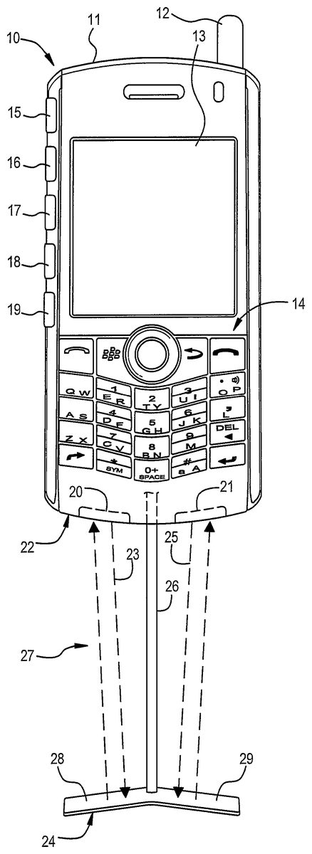
DETAILED DESCRIPTION OF PREFERRED EMBODIMENTS Referring toFIG. 1, a cellular handset of the present invention includes a main body11having an antenna housing12, a graphics display13, and a conventional keypad14. Handset10performs all the normal functions of a cellular phone including communication of voice and/or data signals in a wireless cellular system. Handset10includes additional elements providing it with the capability to act as an ergonomically realistic video game controller for video games utilizing particular combinations of manual movements such as guitar-based games to simulate the playing of a guitar (e.g., pressing fret buttons or making strumming movements according to a particular timing sequence as shown in a game display). Thus, a plurality of fret push buttons15-19is provided in a substantially straight row along one narrow side of main body11. To provide a natural strumming method, a pair of infrared transceivers20and21(each including a respective infrared transmitter or beam generator and a infrared detector) is disposed on a selected surface22of main body11. Preferably, surface22is the bottom edge of main body11as shown. Infrared transceiver20generates a first infrared beam23projected toward a reflector24. Reflector24is held at a spaced position from surface22in alignment with beam23in order to reflect it to the detector in transceiver20. Likewise, transceiver21generates a second infrared beam25projected to receiver24for reflection back to the detector in transceiver21by reflector24. An extension rod26deploys from a retention slot in main body11to slidably extend outward from surface22. Rod26has reflector24mounted at its distal end to create a strumming area27between surface22and reflector24. A preferred embodiment detects strumming as interruptions in beams23and25. With properly selected beam characteristics, however, it is also possible to dispense with a reflector and instead detect the reflection of a beam by the hand or other object controlled by the user. In that alternative embodiment, a return of the beam would not normally be detected except when the user ...
DETAILED DESCRIPTION OF PREFERRED EMBODIMENTS
Referring toFIG. 1, a cellular handset of the present invention includes a main body11having an antenna housing12, a graphics display13, and a conventional keypad14. Handset10performs all the normal functions of a cellular phone including communication of voice and/or data signals in a wireless cellular system.
Handset10includes additional elements providing it with the capability to act as an ergonomically realistic video game controller for video games utilizing particular combinations of manual movements such as guitar-based games to simulate the playing of a guitar (e.g., pressing fret buttons or making strumming movements according to a particular timing sequence as shown in a game display). Thus, a plurality of fret push buttons15-19is provided in a substantially straight row along one narrow side of main body11. To provide a natural strumming method, a pair of infrared transceivers20and21(each including a respective infrared transmitter or beam generator and a infrared detector) is disposed on a selected surface22of main body11. Preferably, surface22is the bottom edge of main body11as shown. Infrared transceiver20generates a first infrared beam23projected toward a reflector24. Reflector24is held at a spaced position from surface22in alignment with beam23in order to reflect it to the detector in transceiver20. Likewise, transceiver21generates a second infrared beam25projected to receiver24for reflection back to the detector in transceiver21by reflector24. An extension rod26deploys from a retention slot in main body11to slidably extend outward from surface22. Rod26has reflector24mounted at its distal end to create a strumming area27between surface22and reflector24. A preferred embodiment detects strumming as interruptions in beams23and25. With properly selected beam characteristics, however, it is also possible to dispense with a reflector and instead detect the reflection of a beam by the hand or other object controlled by the user. In that alternative embodiment, a return of the beam would not normally be detected except when the user makes a control action to move the hand into the beam where it can reflect some of the beam to the detector. In either embodiment, the user moves their fingers or other objects (such as a guitar pick) in strumming area27to create a first manual interaction with the first beam which is detected by the first detector, and a second manual interaction with the second beam which is detected by the second detector.
As described below, two infrared beams are used in order to enable detection of a strumming direction. Thus, when the first manual interaction precedes the second manual interaction, a downstroke strumming command is generated. When the second manual interaction precedes the first manual interaction, it is interpreted as an upstroke strumming command. Beams23and25may preferably be substantially parallel when leaving transceivers20and21. In order to minimize interference or crosstalk between the beams, reflector24preferably has a non-planar shape causing the reflected beams to slightly diverge. Thus, reflector24is shown having a first wing28and a second wing29wherein the ends of wings28and29are slightly further from surface22than at their central attachment point to extension rod26. In other words, reflector24is optically convex to diverge the reflected beams.
Infrared transceivers20and21may comprise commonly available, low cost devices such as those already used in personal digital assistance (PDA) cellular handsets for performing infrared data transmission (e.g., as an IrDA port). The transceivers typically include an infrared light emitting diode (LED) and an infrared photodetector covered by an infrared-transmitting plastic lens. Alternatively, discrete LED's and photodetectors may be employed. Furthermore, other non-infrared light sources and detectors or other proximity sensing technologies such as ultrasonics can be employed in the present invention.
As shown inFIG. 2, main body11has a recess31for receiving extension rod26allowing it to retract so that reflector24is stowed in a recess32within surface22. Preferably, a locking mechanism (not shown) is employed within main body11for firmly locking extension rod26and reflector24in either a retracted or an extended position. For example, a locking system may be activated by rotating reflector24by 180° after it is slid to its extended position. Detents or catch mechanisms can alternatively be used to generate the locks. Since extension rod26is substantially straight and reflector24is elongated in a direction parallel with the side-to-side direction of surface22, recess32must also extend in the side-to-side direction, but it is offset (i.e., adjacent to) the location of transceivers20and21.
Because of a possible offset between the orientation of the transceivers and the positioning of the reflector by the straight rod, the reflector elements on each wing are provided with a particular shape to create a predetermined rotation of beams23and25towards the infrared transceivers. For example, the flat, reflecting surfaces of the reflector wings are sloped at an angle with respect to elongated rod26as shown inFIG. 3. Thus, the predetermined rotation of the infrared beams is perpendicular to the side-to-side dimension of surface22. As a result, the infrared beams are more directly reflected back to the transceivers and the necessary movements of the hand through strumming area27is raised away from extension rod26so that rod26does not interfere with the strumming action.
In addition to a downstroke and an upstroke command, the present invention can recognize a third command in response to the hand being held in such a way that it blocks both infrared beams simultaneously. The third command can correspond with the vibrato, tremolo, or a whammy bar function (i.e., pitch bending).
FIG. 4shows a manner of use of the handset as a guitar controller. Main body11is grasped in a hand35so that the fingers can easily reach across the front of the handset to fret buttons15-19. Reflector24is extended from recess32to create strumming area27within which infrared beams23and25normally circulate. A hand36is brought into strumming area27to sweep over beams23and25sequentially in a downward or upward movement. In addition, hand36can be placed to simultaneously interrupt beams23and25for a third command.
Detection of a strumming command is performed using the preferred method ofFIG. 5. In one preferred embodiment, the infrared generators are always on so that infrared beams23and25are continuous, thereby providing a substantially continuous received signal at both detectors. Waveforms40and41represent a logic signal that is generated in response to the detector signals and having a first logic level when a respective beam is unblocked (i.e., being received) and a second logic level when a respective beam is blocked (i.e., not being received). In the example shown, waveforms40and41have a high logic level during detection of an interruption (i.e., a manual interaction) from the two detectors.
When a first manual interaction begins wherein the users hand begins to block the first beam, waveform40shows a rising leading edge42at the corresponding time. As the user's hand moves downward in the strumming area, eventually the first beam is unblocked resulting in a trailing edge43in waveform40where the interruption detection logic signal is restored to a low logic level. The user's hand continues to move downward and eventually blocks the second beam so that waveform41shows a rising leading edge44. A delay time td1between leading edges42and44is determined by a logic controller which is coupled to the infrared transceivers. If delay td1matches a predetermined delay, then a downstroke strumming command is detected. The predetermined delay has a range of time values according to a maximum speed at which the strumming is to occur. Thus, inadvertent or incorrect blockage of the infrared beams is not interpreted as a strumming stroke. Delays within the predetermined range of times can also be detected and used to indicate different strumming speeds for use in controlling the video game, if desired. On the other hand, the minimum time delay within the range for detecting a strumming command is sufficiently long to accommodate a small error in the user's ability to block both beams simultaneously when intending to generate the third command.
An upstroke command is generated by moving the hand or fingers in an upward direction through the strumming area to generate first rising edge45in waveform41and then a second rising edge46in waveform40, wherein a time delay td2between rising edges45and46is within the predetermined delay range.
To provide further flexibility in generating fret commands using appropriate push buttons, the fret buttons may be mounted to a pivotally-attached swing arm having a button surface substantially perpendicular to surface22as shown inFIGS. 6-9. Thus, a swing arm50is attached to upper and lower ends of main body11at pivot points51and52such that swing arm50swings or rotates around main body11over a range of at least about 180° between a right-handed playing position shown inFIG. 6and a left-hand playing position shown inFIG. 9. Detents or other holding mechanisms may preferably be associated with pivots51and/or52for maintaining swing arm50in its end positions shown inFIGS. 6 and 9.
FIG. 7shows swing arm50being rotated between opposite sides. It may be desirable to provide additional holding positions using detents at such an intermediate position to adapt use of the handset controls to a different type of video game, for example.FIG. 8shows an end view with swing arm50in an intermediate position. An aperture58is provided through swing arm50to be aligned with infrared transceivers20and21when in its end positions so that swing arm50does not interfere with the infrared beams.
FIG. 10shows an alternative embodiment employing a pair of beam generators comprising infrared LED's60and61generating beams62and63which are projected toward a reflector64. Due to a slightly concave shape of reflector64, beams62and63are converged to a single detector65. Instead of providing reflector64with a non-planar shape to converge the beams, an optically modified surface such as a series of saw tooth-shaped grooves can alternatively be used.
In order to separately detect interruption of beams62and63using a single detector65, the beams are modulated in different ways in order to enable reception of each beam to be distinguishable. One modulation scheme is to alternately pulse each LED60and61to alternately produce a detectable signal at detector65. Pulsing is required to occur at a period shorter than the time in which significant movement of the hand sweeping through the strumming area could move an appreciable distance compared to the width of the beams.
Alternatively, each beam can be modulated with an information content that is uniquely recoverable by detector65to detect at what times each beam is still being received. For example, each beam can be amplitude modulated or frequency modulated according to unique frequencies or information content that are non-overlapping. Various code transmission protocols could be used as are known in the art.
A hardware implementation of the present information is shown in greater detail inFIG. 11. A first LED70and a first photodetector71are coupled to an interface and driver circuit72. Devices70-72may comprise a commercially available infrared transceiver, for example. Interface and driver circuit72operates under control of command logic73. In one preferred embodiment, command logic73provides an activation signal to driver and interface circuit72when the handset is in a mode to detect strumming commands. Interface and driver circuit72automatically controls operation of LED70and photodetector71and provides an interruption signal to command logic73when its respective beam is being interrupted. When a single detector is being used, modulation of the beam and demodulation of the detected beam may preferably be performed by interface and driver circuit72, but could alternative be handled by command logic block73. A second LED74and photodetector75are connected to another interface and driver circuit76similarly connected to command logic73. Fret buttons77are coupled to command logic73through an interface78.
Command logic73compares interruption events detected for each respective beam to interpret the occurrence of upstroke and downstroke commands, as well as the third command representing the pitch bending function. Thus, if interruption events occur with rising edges within a predetermined shortest delay time, then a third command is generated. If interruption events occur according to a delay within the predetermined delay range, then an upstroke or downstroke command is generated. The generated commands are provided to a game controller80which is coupled to a game display81. Game controller80implements the actual video game software such as the guitar simulation and may reside either on the handset itself or remotely on a game platform accessed by the handset over the cellular network.
FIG. 12shows a network system for supporting multiplayer games accessible to a player using a handset82of the present invention. Handset82wirelessly connects to a base station83in turn coupled to a base station controller (BSC)84. The wireless cellular system preferably supports digital data transmission to a packet data serving node (PDSN)85which is coupled to an IP network90(which may preferably be owned and operated by the wireless service provider). A central game controller91is coupled to IP network90and implements the video game in response to inputs from the player using handset82. A second player using a handset86may be similarly coupled to a base station87and a BSC88in order to send digital data commands to PDSN85for forwarding to game controller91through IP network90. Game controller91may be configured to provide video game output to a designated set top box (STB)92associated with a television display93. Thus, the players using handsets82and86do not need to view the game using displays on their handsets but can playing the video game from the location of TV monitor93to view the game display. Additional players can be joined to a game from a PC or other game console94coupled by a gateway95to IP network90. Alternatively, a PC or console94can be utilized by game controller91as the game display.
Claims
- A cellular handset for manipulating a video game, comprising: a first beam generator projecting a first beam from a selected surface of the handset;a second beam generator projecting a second beam from the selected surface of the handset;a first detector proximate the selected surface for detecting a first manual interaction of a user with the first beam;a second detector proximate the selected surface for detecting a second manual interaction of a user with the second beam;and command logic coupled to the first and second detectors for interpreting a first manual interaction preceding a second manual interaction as a downstroke command and for interpreting a second manual interaction preceding a first manual interaction as an upstroke command, wherein the command logic is adapted to be coupled to a game controller to transmit the downstroke and upstroke commands as input to the video game.
- The cellular handset of claim 1 wherein the command logic further interprets a simultaneous occurrence of the first and second manual interactions as a third command.
- The cellular handset of claim 2 wherein the video game is a guitar simulation game, wherein the downstroke and upstroke commands correspond to strumming of a guitar, and wherein the third command corresponds to a pitch bending of the guitar.
- The cellular handset of claim 1 further comprising: a reflector held at a spaced position from the selected surface in alignment with the first and second beams adapted to reflect them to the first and second detectors, respectively;wherein the first and second manual interactions each comprises a respective manual interruption of the reflections of the first and second beams to the first and second detectors, respectively.
- The cellular handset of claim 4 further comprising an extension rod that slidably extends from the selected surface, wherein the reflector is mounted to a distal end of the extension rod.
- The cellular handset of claim 5 wherein the extension rod is substantially straight, wherein the reflector is elongated in a direction parallel with a side-to-side direction of the selected surface of the handset, and wherein the reflector has first and second reflecting elements receiving the first and second beams, respectively, and shaped to provide a predetermined rotation of the first and second beams perpendicular to the parallel direction and toward the first and second detectors.
- The cellular handset of claim 5 wherein the reflector is elongated in a direction parallel with a side-to-side direction of the selected surface of the handset, and wherein the reflector has first and second reflecting elements receiving the first and second beams, respectively, and shaped to provide a predetermined divergence of the reflected first and second beams so that the first beam is reflected in a direction away from the second detector and the second beam is reflected in another direction away from the first detector.
- The cellular handset of claim 1 further comprising: a plurality of push buttons disposed on a second surface substantially perpendicular to the selected surface coupled to the command logic, wherein a user actuates the push buttons to generate signals interpreted by the command logic as respective fret commands.
- The cellular handset of claim 8 wherein the second surface is provided on a pivotally-attached swing arm capable of swinging over a range of about 180° around the cellular handset to adapt the push buttons to be actuated from either a right handed configuration or a left handed configuration.
- The cellular handset of claim 1 wherein the first and second beam generators are comprised of infrared LED's and wherein the first and second detectors are comprised of infrared photodetectors.
- A cellular handset for manipulating a video game, comprising: a first beam generator projecting a first beam from a selected surface of the handset;a second beam generator projecting a second beam from the selected surface of the handset;a detector proximate the selected surface for detecting a first manual interaction of a user with the first beam and a second manual interaction of the user with the second beam;and command logic coupled to the detector for interpreting a first manual interaction preceding a second manual interaction as a downstroke command and for interpreting a second manual interaction preceding a first manual interaction as an upstroke command, wherein the command logic is adapted to be coupled to a game controller to transmit the downstroke and upstroke commands as input to the video game.
- The cellular handset of claim 11 wherein the command logic further interprets a simultaneous occurrence of the first and second manual interactions as a third command.
- The cellular handset of claim 12 wherein the video game is a guitar simulation game, wherein the downstroke and upstroke commands correspond to strumming of a guitar, and wherein the third command corresponds to a pitch bending of the guitar.
- The cellular handset of claim 11 further comprising: a reflector held at a spaced position from the selected surface in alignment with the first and second beams adapted to reflect them to the detector;wherein the first and second manual interactions each comprises a respective manual interruption of the reflections of the first and second beams to the detector.
- The cellular handset of claim 14 further comprising an extension rod that slidably extends from the selected surface, wherein the reflector is mounted to a distal end of the extension rod.
- The cellular handset of claim 14 further comprising: first and second drivers for activating the first and second beam generators according to first and second beam modulations, respectively;and a demodulator for sensing the first and second beam modulations and for detecting the first and second manual interactions in response to a respective beam modulation being absent.
- The cellular handset of claim 11 further comprising: a plurality of push buttons disposed on a second surface substantially perpendicular to the selected surface coupled to the command logic, wherein a user actuates the push buttons to generate signals interpreted by the command logic as respective fret commands.
- The cellular handset of claim 17 wherein the second surface is provided on a pivotally-attached swing arm capable of swinging over a range of about 180° around the cellular handset to adapt the push buttons to be actuated from either a right handed configuration or a left handed configuration.
- The cellular handset of claim 11 wherein the first and second beam generators are comprised of infrared LED's and wherein the detector is comprised of an infrared photodetector.
- A method of controlling a video game using a cellular handset, comprising the steps of: extending a reflector from a main body of the cellular handset;directing first and second interruptible beams from the main body to the reflector;detecting the return of the first and second beams to the main body;detecting respective interruptions resulting from blocking the first and second beams;generating a downstroke command when an interruption of the first beam precedes an interruption of the second beam by a predetermined delay;generating an upstroke command when an interruption of the second beam precedes an interruption of the first beam by the predetermined delay;and transmitting the downstroke and upstroke commands to a game controller as input to a video game.
- The method of claim 20 wherein the predetermined delay is comprised of a range of time values between a minimum and a maximum.
- The method of claim 20 further comprising the steps of: generating a third command when a substantially simultaneous interruption of the first and second beam is detected;and transmitting the third command to the game controller as input to the video game.
- The method of claim 20 wherein the video game comprises a guitar simulation, wherein the upstroke and downstroke commands correspond to strumming, and wherein the method further comprises the step of: generating fret commands in response to manual actuation of push buttons on the main body;and transmitting the fret commands to the game controller as input to the video game.
Disclaimer: Data collected from the USPTO and may be malformed, incomplete, and/or otherwise inaccurate.