U.S. Pat. No. 7,896,733
METHOD AND APPARATUS FOR PROVIDING INTERESTING AND EXCITING VIDEO GAME PLAY USING A STABILITY/ENERGY METER
AssigneeNintendo Co., Ltd.
Issue DateSeptember 14, 2006
Illustrative Figure
Abstract
A power or life meter is displayed in a video game. Firing a weapon depletes the indicated power. Meanwhile, the power is recharged at a predetermined rate. If the indicated power exceeds capacity, the game character is adversely impacted. If the indicated power is completely depleted, the game character loses a benefit.
Description
DETAILED DESCRIPTION Techniques described herein can be performed on any type of computer graphics system including a personal computer, a home video game machine, a portable video game machine, a networked server and display, a cellular telephone, a personal digital assistant, or any other type of device or arrangement having computation and graphical display capabilities. One exemplary illustrative non-limiting implementation includes a home video game system such as the Nintendo Wii 3D video game system, a Nintendo DS or other 3D capable interactive computer graphics display system. One exemplary illustrative non-limiting implementation is described below, but other implementations are possible. Exemplary Video Game Platform FIG. 1shows a non-limiting example game system10including a game console100, a television102and a controller107. Game console100executes a game program or other application stored on optical disc104inserted into slot105formed in housing110thereof. The result of the execution of the game program or other application is displayed on display101of television102to which game console100is connected by cable106. Audio associated with the game program or other application is output via speakers109of television102. While an optical disk is shown inFIG. 1for use in storing video game software, the game program or other application may alternatively or additionally be stored on other storage media such as semiconductor memories, magneto-optical memories, magnetic memories and the like and/or downloaded over a network or by other means. Controller107wirelessly transmits data such as game control data to the game console100. The game control data may be generated using an operation section of controller107having, for example, a plurality of operation buttons, a key, a stick and the like. Controller107may also wirelessly receive data transmitted from game console100. Any one of various wireless protocols such as Bluetooth (registered trademark) may be used for the wireless transmissions between controller107and game console100. As discussed below, controller107also includes an imaging information calculation ...
DETAILED DESCRIPTION
Techniques described herein can be performed on any type of computer graphics system including a personal computer, a home video game machine, a portable video game machine, a networked server and display, a cellular telephone, a personal digital assistant, or any other type of device or arrangement having computation and graphical display capabilities. One exemplary illustrative non-limiting implementation includes a home video game system such as the Nintendo Wii 3D video game system, a Nintendo DS or other 3D capable interactive computer graphics display system. One exemplary illustrative non-limiting implementation is described below, but other implementations are possible.
Exemplary Video Game Platform
FIG. 1shows a non-limiting example game system10including a game console100, a television102and a controller107.
Game console100executes a game program or other application stored on optical disc104inserted into slot105formed in housing110thereof. The result of the execution of the game program or other application is displayed on display101of television102to which game console100is connected by cable106. Audio associated with the game program or other application is output via speakers109of television102. While an optical disk is shown inFIG. 1for use in storing video game software, the game program or other application may alternatively or additionally be stored on other storage media such as semiconductor memories, magneto-optical memories, magnetic memories and the like and/or downloaded over a network or by other means.
Controller107wirelessly transmits data such as game control data to the game console100. The game control data may be generated using an operation section of controller107having, for example, a plurality of operation buttons, a key, a stick and the like. Controller107may also wirelessly receive data transmitted from game console100. Any one of various wireless protocols such as Bluetooth (registered trademark) may be used for the wireless transmissions between controller107and game console100.
As discussed below, controller107also includes an imaging information calculation section for capturing and processing images from light-emitting devices108aand108b. Preferably, a center point between light-emitting devices108aand108bis aligned with a vertical center line of television101. The images from light-emitting devices108aand108bcan be used to determine a direction in which controller107is pointing as well as a distance of controller107from display101. By way of example without limitation, light-emitting devices108aand108bmay be implemented as two LED modules (hereinafter, referred to as “markers”) provided in the vicinity of a display screen of television102. The markers each output infrared light and the imaging information calculation section of controller107detects the light output from the LED modules to determine a direction in which controller107is pointing and a distance of controller107from display101as mentioned above. As will become apparent from the description below, various implementations of the system and method for simulating the striking of an object described herein do not require use such markers.
Although markers108aand108bare shown inFIG. 1as being above television100, they may also be positioned below television100or in other configurations.
With reference to the block diagram ofFIG. 2, game console100includes a RISC central processing unit (CPU)204for executing various types of applications including (but not limited to) video game programs. CPU204executes a boot program stored in a boot ROM (not shown) to initialize game console100and then executes an application (or applications) stored on optical disc104which is inserted in optical disk drive208. User-accessible eject button210provided on housing110of game console100may be used to eject an optical disk from disk drive208.
In one example implementation, optical disk drive208receives both optical disks of a first type (e.g., of a first size and/or of a first data structure, etc.) containing applications developed for execution by CPU204and graphics processor216and optical disks of a second type (e.g., of a second size and/or a second data structure) containing applications originally developed for execution by a different CPU and/or graphics processor. For example, the optical disks of the second type may be applications originally developed for the Nintendo GameCube platform.
CPU204is connected to system LSI202that includes graphics processing unit (GPU)216with an associated graphics memory220, audio digital signal processor (DSP)218, internal main memory222and input/output (IO) processor224.
IO processor224of system LSI202is connected to one or more USB ports226, one or more standard memory card slots (connectors)228, WiFi module230, flash memory232and wireless controller module240.
USB ports226are used to connect a wide variety of external devices to game console100. These devices include by way of example without limitation game controllers, keyboards, storage devices such as external hard-disk drives, printers, digital cameras, and the like. USB ports226may also be used for wired network (e.g., LAN) connections. In one example implementation, two USB ports226are provided.
Standard memory card slots (connectors)228are adapted to receive industry-standard-type memory cards (e.g., SD memory cards). In one example implementation, one memory card slot228is provided. These memory cards are generally used as data carriers. For example, a player may store game data for a particular game on a memory card and bring the memory card to a friend's house to play the game on the friend's game console. The memory cards may also be used to transfer data between the game console and personal computers, digital cameras, and the like.
WiFi module230enables game console100to be connected to a wireless access point. The access point may provide internet connectivity for on-line gaming with players at other locations (with or without voice chat capabilities), as well as web browsing, e-mail, file downloads (including game downloads) and many other types of on-line activities. In some implementations, WiFi module may also be used for communication with other game devices such as suitably-equipped hand-held game devices. Module230is referred to herein as “WiFi”, which is generally used in connection with the family of IEEE 802.11 specifications. However, game console100may of course alternatively or additionally use wireless modules that conform with other wireless standards.
Flash memory232stores, by way of example without limitation, game save data, system files, internal applications for the console and downloaded data (such as games).
Wireless controller module240receives signals wirelessly transmitted from one or more controllers107and provides these received signals to IO processor224. The signals transmitted by controller107to wireless controller module240may include signals generated by controller107itself as well as by other devices that may be connected to controller107. By way of example, some games may utilize separate right- and left-hand inputs. For such games, another controller (not shown) may be connected to controller107and controller107could transmit to wireless controller module240signals generated by itself and by the other controller.
Wireless controller module240may also wirelessly transmit signals to controller107. By way of example without limitation, controller107(and/or another game controller connected thereto) may be provided with vibration circuitry and vibration circuitry control signals may be sent via wireless controller module240to control the vibration circuitry. By way of further example without limitation, controller107may be provided with (or be connected to) a speaker (not shown) and audio signals for output from this speaker may be wirelessly communicated to controller107via wireless controller module240. By way of still further example without limitation, controller107may be provided with (or be connected to) a display device (not shown) and display signals for output from this display device may be wirelessly communicated to controller107via wireless controller module240.
Proprietary memory card slots246are adapted to receive proprietary memory cards. In one example implementation, two such slots are provided. These proprietary memory cards have some non-standard feature such as a non-standard connector or a non-standard memory architecture. For example, one or more of the memory card slots246may be adapted to receive memory cards developed for the Nintendo GameCube platform. In this case, memory cards inserted in such slots can transfer data from games developed for the GameCube platform. In an example implementation, memory card slots246may be used for read-only access to the memory cards inserted therein and limitations may be placed on whether data on these memory cards can be copied or transferred to other storage media such as standard memory cards inserted into slots228.
One or more controller connectors244are adapted for wired connection to respective game controllers. In one example implementation, four such connectors are provided for wired connection to game controllers for the Nintendo GameCube platform. Alternatively, connectors244may be connected to respective wireless receivers that receive signals from wireless game controllers. These connectors enable players, among other things, to use controllers for the Nintendo GameCube platform when an optical disk for a game developed for this platform is inserted into optical disk drive208.
A connector248is provided for connecting game console100to DC power derived, for example, from an ordinary wall outlet. Of course, the power may be derived from one or more batteries.
GPU216performs image processing based on instructions from CPU204. GPU216includes, for example, circuitry for performing calculations necessary for displaying three-dimensional (3D) graphics. GPU216performs image processing using graphics memory220dedicated for image processing and a part of internal main memory222. GPU216generates image data for output to television102by audio/video connector214via audio/video IC (interface)212.
Audio DSP218performs audio processing based on instructions from CPU204. The audio generated by audio DSP218is output to television102by audio/video connector214via audio/video IC212.
External main memory206and internal main memory222are storage areas directly accessible by CPU204. For example, these memories can store an application program such as a game program read from optical disc104by the CPU204, various types of data or the like.
ROM/RTC238includes a real-time clock and preferably runs off of an internal battery (not shown) so as to be usable even if no external power is supplied. ROM/RTC238also may include a boot ROM and SRAM usable by the console.
Power button242is used to power game console100on and off. In one example implementation, power button242must be depressed for a specified time (e.g., one or two seconds) to turn the consoled off so as to reduce the possibility of inadvertently turn-off. Reset button244is used to reset (reboot) game console100.
With reference toFIGS. 3 and 4, example controller107includes a housing301on which operating controls302a-302hare provided. Housing301has a generally parallelepiped shape and is sized to be conveniently holdable in a player's hand. Cross-switch302ais provided at the center of a forward part of a top surface of the housing301. Cross-switch302ais a cross-shaped four-direction push switch which includes operation portions corresponding to the directions designated by the arrows (front, rear, right and left), which are respectively located on cross-shaped projecting portions. A player selects one of the front, rear, right and left directions by pressing one of the operation portions of the cross-switch302a. By actuating cross-switch302a, the player can, for example, move a character in different directions in a virtual game world.
Cross-switch302ais described by way of example and other types of operation sections may be used. By way of example without limitation, a composite switch including a push switch with a ring-shaped four-direction operation section and a center switch may be used. By way of further example without limitation, an inclinable stick projecting from the top surface of housing301that outputs signals in accordance with the inclining direction of the stick may be used. By way of still further example without limitation, a horizontally slidable disc-shaped member that outputs signals in accordance with the sliding direction of the disc-shaped member may be used. By way of still further example without limitation, a touch pad may be used. By way of still further example without limitation, separate switches corresponding to at least four directions (e.g., front, rear, right and left) that output respective signals when pressed by a player may be used.
Buttons (or keys)302bthrough302gare provided rearward of cross-switch302aon the top surface of housing301. Buttons302bthrough302gare operation devices that output respective signals when a player presses them. For example, buttons302bthrough302dare respectively an “X” button, a “Y” button and a “B” button and buttons302ethrough302gare respectively a select switch, a menu switch and a start switch, for example. Generally, buttons302bthrough302gare assigned various functions in accordance with the application being executed by game console100. In an exemplary arrangement shown inFIG. 3, buttons302bthrough302dare linearly arranged along a front-to-back centerline of the top surface of housing301. Buttons302ethrough302gare linearly arranged along a left-to-right line between buttons302band302d. Button302fmay be recessed from a top surface of housing701to reduce the possibility of inadvertent pressing by a player grasping controller107.
Button302his provided forward of cross-switch302aon the top surface of the housing301. Button302his a power switch for remote on-off switching of the power to game console100. Button302hmay also be recessed from a top surface of housing301to reduce the possibility of inadvertent pressing by a player.
A plurality (e.g., four) of LEDs304is provided rearward of button302con the top surface of housing301. Controller107is assigned a controller type (number) so as to be distinguishable from the other controllers used with game console100and LEDs may304may be used to provide a player a visual indication of this assigned controller number. For example, when controller107transmits signals to wireless controller module240, one of the plurality of LEDs corresponding to the controller type is lit up.
With reference toFIG. 3B, a recessed portion308is formed on a bottom surface of housing301. Recessed portion308is positioned so as to receive an index finger or middle finger of a player holding controller107. A button302iis provided on a rear, sloped surface308aof the recessed portion. Button302ifunctions, for example, as an “A” button which can be used, by way of illustration, as a trigger switch in a shooting game.
As shown inFIG. 4, an imaging element305ais provided on a front surface of controller housing301. Imaging element305ais part of an imaging information calculation section of controller107that analyzes image data received from markers108aand108b. Imaging information calculation section305has a maximum sampling period of, for example, about 200 frames/sec., and therefore can trace and analyze even relatively fast motion of controller107. The techniques described herein of simulating the striking of an object can be achieved without using information from imaging information calculation section305, and thus further detailed description of the operation of this section is omitted. Additional details may be found in Application No. 60/716,937, entitled “VIDEO GAME SYSTEM WITH WIRELESS MODULAR HANDHELD CONTROLLER,” filed on Sep. 15, 2005; 60/732,648, entitled “INFORMATION PROCESSING PROGRAM,” filed on Nov. 3, 2005; and application No. 60/732,649, entitled “INFORMATION PROCESSING SYSTEM AND PROGRAM THEREFOR,” filed on Nov. 3, 2005. The entire contents of each of these applications are incorporated herein.
Connector303is provided on a rear surface of controller housing301. Connector303is used to connect devices to controller107. For example, a second controller of similar or different configuration may be connected to controller107via connector303in order to allow a player to play games using game control inputs from both hands. Other devices including game controllers for other game consoles, input devices such as keyboards, keypads and touchpads and output devices such as speakers and displays may be connected to controller107using connector303.
For ease of explanation in what follows, a coordinate system for controller107will be defined. As shown inFIGS. 3 and 4, a left-handed X, Y, Z coordinate system has been defined for controller107. Of course, this coordinate system is described by way of example without limitation and the systems and methods described herein are equally applicable when other coordinate systems are used.
As shown in the block diagram ofFIG. 5, controller107includes a three-axis, linear acceleration sensor507that detects linear acceleration in three directions, i.e., the up/down direction (Z-axis shown inFIGS. 3 and 4), the left/right direction (X-axis shown inFIGS. 3 and 4), and the forward/backward direction (Y-axis shown inFIGS. 3 and 4). Alternatively, a two-axis linear accelerometer that only detects linear acceleration along each of the Y-axis and Z-axis may be used or a one-axis linear accelerometer that only detects linear acceleration along the Z-axis may be used. Generally speaking, the accelerometer arrangement (e.g., three-axis or two-axis) will depend on the type of control signals desired. As a non-limiting example, the three-axis or two-axis linear accelerometer may be of the type available from Analog Devices, Inc. or STMicroelectronics N.V. Preferably, acceleration sensor507is an electrostatic capacitance or capacitance-coupling type that is based on silicon micro-machined MEMS (micro-electromechanical systems) technology. However, any other suitable accelerometer technology (e.g., piezoelectric type or piezoresistance type) now existing or later developed may be used to provide three-axis or two-axis linear acceleration sensor507.
As one skilled in the art understands, linear accelerometers, as used in acceleration sensor507, are only capable of detecting acceleration along a straight line corresponding to each axis of the acceleration sensor. In other words, the direct output of acceleration sensor507is limited to signals indicative of linear acceleration (static or dynamic) along each of the two or three axes thereof. As a result, acceleration sensor507cannot directly detect movement along a non-linear (e.g. arcuate) path, rotation, rotational movement, angular displacement, tilt, position, attitude or any other physical characteristic.
However, through additional processing of the linear acceleration signals output from acceleration sensor507, additional information relating to controller107can be inferred or calculated (i.e., determined), as one skilled in the art will readily understand from the description herein. For example, by detecting static, linear acceleration (i.e., gravity), the linear acceleration output of acceleration sensor507can be used to determine tilt of the object relative to the gravity vector by correlating tilt angles with detected linear acceleration. In this way, acceleration sensor507can be used in combination with micro-computer502of controller107(or another processor) to determine tilt, attitude or position of controller107. Similarly, various movements and/or positions of controller107can be calculated through processing of the linear acceleration signals generated by acceleration sensor507when controller107containing acceleration sensor307is subjected to dynamic accelerations by, for example, the hand of a user, as will be explained in detail below.
In another embodiment, acceleration sensor507may include an embedded signal processor or other type of dedicated processor for performing any desired processing of the acceleration signals output from the accelerometers therein prior to outputting signals to micro-computer502. For example, the embedded or dedicated processor could convert the detected acceleration signal to a corresponding tilt angle (or other desired parameter) when the acceleration sensor is intended to detect static acceleration (i.e., gravity).
Returning toFIG. 5, image information calculation section505of controller107includes infrared filter528, lens529, imaging element305aand image processing circuit530. Infrared filter528allows only infrared light to pass therethrough from the light that is incident on the front surface of controller107. Lens529collects and focuses the infrared light from infrared filter528on imaging element305a. Imaging element305ais a solid-state imaging device such as, for example, a CMOS sensor or a CCD. Imaging element305acaptures images of the infrared light from markers108aand108bcollected by lens309. Accordingly, imaging element305acaptures images of only the infrared light that has passed through infrared filter528and generates image data based thereon. This image data is processed by image processing circuit520which detects an area thereof having high brightness, and, based on this detecting, outputs processing result data representing the detected coordinate position and size of the area to communication section506. From this information, the direction in which controller107is pointing and the distance of controller107from display101can be determined.
Vibration circuit512may also be included in controller107. Vibration circuit512may be, for example, a vibration motor or a solenoid. Controller107is vibrated by actuation of the vibration circuit512(e.g., in response to signals from game console100), and the vibration is conveyed to the hand of the player holding controller107. Thus, a so-called vibration-responsive game may be realized.
As described above, acceleration sensor507detects and outputs the acceleration in the form of components of three axial directions of controller107, i.e., the components of the up-down direction (Z-axis direction), the left-right direction (X-axis direction), and the front-rear direction (the Y-axis direction) of controller107. Data representing the acceleration as the components of the three axial directions detected by acceleration sensor507is output to communication section506. Based on the acceleration data which is output from acceleration sensor507, a motion of controller107can be determined.
Communication section506includes micro-computer502, memory503, wireless module504and antenna505. Micro-computer502controls wireless module504for transmitting and receiving data while using memory503as a storage area during processing. Micro-computer502is supplied with data including operation signals (e.g., cross-switch, button or key data) from operation section302, acceleration signals in the three axial directions (X-axis, Y-axis and Z-axis direction acceleration data) from acceleration sensor507, and processing result data from imaging information calculation section505. Micro-computer502temporarily stores the data supplied thereto in memory503as transmission data for transmission to game console100. The wireless transmission from communication section506to game console100is performed at a predetermined time interval. Because game processing is generally performed at a cycle of 1/60 sec. (16.7 ms), the wireless transmission is preferably performed at a cycle of a shorter time period. For example, a communication section structured using Bluetooth (registered trademark) technology can have a cycle of 5 ms. At the transmission time, micro-computer502outputs the transmission data stored in memory503as a series of operation information to wireless module504. Wireless module504uses, for example, Bluetooth (registered trademark) technology to send the operation information from antenna505as a carrier wave signal having a specified frequency. Thus, operation signal data from operation section302, the X-axis, Y-axis and Z-axis direction acceleration data from acceleration sensor507, and the processing result data from imaging information calculation section505are transmitted from controller107. Game console100receives the carrier wave signal and demodulates or decodes the carrier wave signal to obtain the operation information (e.g., the operation signal data, the X-axis, Y-axis and Z-axis direction acceleration data, and the processing result data). Based on this received data and the application currently being executed, CPU204of game console100performs application processing. If communication section506is structured using Bluetooth (registered trademark) technology, controller107can also receive data wirelessly transmitted thereto from devices including game console100.
The exemplary illustrative non-limiting system described above can be used to execute software stored on optical disk104or in other memory that controls it to interactive generate displays on display101of a progressively deformed object in response to user input provided via controller107. Exemplary illustrative non-limiting software controlled techniques for generating such displays will now be described.
Example Hyper Mode Game Play
FIG. 6shows an example screen display1002of a first person shooter type combat game. Other types of games including driving games, space games, adventure games, sports games or any other type of game could also be used. In the example shown, a power or life meter or gauge1004is displayed on display1002. Gauge1004includes a block indicator1006and a power gauge indicator1008. The block indicator1006can display for example a block of life or power (one block may correspond to some number of points such as for example 100 points). The power gauge indicator1008reflects the amount of power a player has available. Blocks can be earned by accomplishing particular tasks within the game for example.
In one exemplary illustrative non-limiting implementation, the game indicator1008is similar to a thermometer or for example the type of graphical display provided by an audio graphic equalizer. One can readily tell by looking at the gauge how much power a game player has and how much power has been depleted. In one example non-limiting implementation, the gauge level rises (e.g., moves to the right or upwards) as the amount of stored power in a power reservoir increases and moves to the left or downwards as the amount of power decreases. Generally, the game player wishes to maintain sufficient power as indicated by the power gauge to accomplish gaming tasks.
FIG. 6also shows a weapon1010. In the exemplary illustrative non-limiting implementation, each time the game character fires weapon1010, the power indicated by the gauge1008decreases. If the gauge ever falls to zero level and thus becomes completely depleted, the game character may no longer be able to fire weapon1010and can no longer attack enemies. The game character can obtain power for display by indicator1008automatically as time goes by and/or by accomplishing certain tasks.
In one exemplary illustrative non-limiting implementation, the game player can choose to enter a special mode called “hyper mode” by depressing a control or menu selection. In one exemplary illustrative non-limiting implementation, it may cost the game character some power (one block) to enter hyper mode. However, certain benefits are achieved in hyper mode. For example, in one exemplary illustrative non-limiting implementation, the game character becomes less vulnerable or invulnerable to enemy attack whenever the game character is in hyper mode.
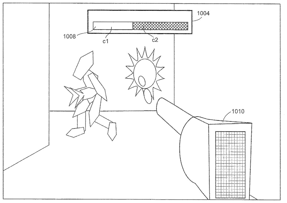
FIG. 7shows an example illustrative non-limiting hyper mode game display. In this example illustration, the gauge1004continues to provide a gauge indicator1008indicating the amount of power available and stored in a power reservoir. In the example shown, the “C1” part of the gauge indicator1008indicates the remaining energy available for shooting a weapon, and the “C2” portion of the gauge indicator indicates the amount of energy that has been used or depleted. In one exemplary illustrative non-limiting implementation, when the game character first enters hyper mode, the gauge indicator1008is filled to an intermediate level. Each time the game player fires weapon1010, the amount of power indicated by gauge indicator1008decreases. If the “C1” bar indicator ever falls to zero, meaning that the energy has been entirely depleted, hyper mode is over and the game character again becomes vulnerable. However, if the game player does not fire weapon1010for a while, the game play automatically replenishes the energy within the indicator gauge1008and the “C1” bar increases in size.
In the exemplary illustrative non-limiting implementation, if the “C1” bar every exceeds a predetermined level (e.g., extends over the entirety of the gauge to indicate for example maximum capacity has been exceeded), the game is over.
In the exemplary illustrative non-limiting implementation, the game player must carefully shoot game objects with weapons1010while watching the indicator gauge1008carefully so that it never exceeds its capacity. The game player must thus maintain a situation such that both a “C1” and a “C2” portion of the gauge exists in the indication in order to maintain the game character within hyper mode but not causing a “game over” situation. This provides an interesting ebb and flow to the game action. Inexperienced players may immediately recognize the danger in remaining in hyper mode and try and leave hyper mode as rapidly as possible in order to eliminate the danger of “game over.” More experienced players will recognize the advantages in terms of invulnerability or other beneficial effects of remaining in hyper mode as long as possible but must always be mindful of the danger of a “game over” should the power meter indicate energy capacity has been exceeded. The experienced player can fire a weapon periodically to decrease energy levels but does not want to deplete the energy so much that hyper mode will be over or so that there will be no power left for firing a weapon defensively. A game player will thus constantly be conducting a risk/benefit analysis in which weapon firing will increase the likelihood of leaving hyper mode but may also prevent instability that could lead to destruction. The “shoot and recharge, shoot and recharge” ebb and flow strategies that experienced players will adopt provide an interesting and fun addition to a first person shooter or other game.
FIG. 8is a flowchart of exemplary illustrative non-limiting program control steps. The gauge is displayed at block1102. As time passes, the gauge level is recharged (blocks1104,1106). The gauge level is depleted each time the player fires a weapon (block1108,1110). If the gauge level ever exceeds a predetermined maximum, the game is over (blocks1112,1114). If the gauge level is ever completed depleted, hyper mode is exited and the player returns to normal game play (blocks1116,1118).
While the technology herein has been described in connection with exemplary illustrative non-limiting implementations, the invention is not to be limited by the disclosure. For example, while the exemplary illustrative non-limiting implementation displays a gauge, other forms of indication are possible such as brightness or sound. The special powers existing in hypermode can be any time of benefit including ability to score more easily, ability to accomplish any sort of task, or any special condition or characteristic. The adverse consequence of exceeding maximum power could be any adverse consequence. The invention is intended to be defined by the claims and to cover all corresponding and equivalent arrangements whether or not specifically disclosed herein.
Claims
- A video game play method for use with a video game system including a processor, a display, at least one user input device, and a graphics processor configured to produce animated graphics at least in part in response to the least one user input device for display on the display, the method comprising: causing said processor to operate with a display, at least one user input device and a graphics processor to: display a power meter providing a power indication on a single scale;automatically replenishing the power indication displayed on the single scale by the power meter without requiring user input;depleting the power indication displayed on the single scale by the power meter based at least in part on game player inputs;comparing the power indication displayed by the power meter on the single scale to a first predetermined threshold and to a second predetermined threshold different from the first predetermined threshold;if the power indication is less than the first predetermined threshold, subjecting a game character to a first consequence;and if the power indication is greater than the second predetermined threshold, subjecting the game character to a second consequence different from said first consequence, wherein the second consequence is an adverse consequence for the game character.
- The method of claim 1 wherein said first consequence is to make the game character more vulnerable to attack.
- The method of claim 1 wherein the second consequence is game over.
- The method of claim 1 wherein the second consequence is game character destruction.
- The method of claim 1 wherein replenishing the power indication displayed on the single scale of the power meter is accomplished through a passage of time and not based on user input.
- The video game play method of claim 1 wherein the video game play method facilitates game player inputs to balance against the passage of time for managing the power indicated on the single scale of the power meter.
- A video game play method for use on a video game system including a processor, a display, at least one user input device, and a graphics processor configured to produce animated graphics at least in part in response to the least one user input device for display on the display, the method comprising: causing said processor to operate with a display, at least one user input device and a graphics processor to: display a power meter providing a power indication on a single scale;replenishing and depleting the power indication displayed on the single scale of the power meter;at least one of replenishing and depleting being performed automatically without requiring user input;comparing the power indicated by the single scale on the power meter to a first predetermined threshold and to a second predetermined threshold different from said first predetermined threshold;if the power indicated by the single scale on the power meter is less than the first predetermined threshold, subjecting a game player to a first consequence;and if the power indicated by the single scale on the power meter is greater than the second predetermined threshold, subjecting the game player to a second consequence different from the first consequence, wherein the second consequence is an adverse consequence for the game character.
- The method of claim 7 further comprising initiating an optional game mode in response to game player inputs, and wherein at least one of said first and second consequences terminates said optional game mode.
- . The method of claim 8 wherein said first consequence terminates said optional game mode, and said second consequence terminates a game character.
- The method of claim 8 further comprising transitioning out of the optional game mode if a video game play condition is met.
- The method of claim 10 wherein the video game play condition is if the game player has spent more than a programmed amount of time in the optional game mode.
- A non-transitory computer readable medium storing computer-readable instructions for performing a video game play method for use on a video game system including a processor, a display, at least one user input device, and a graphics processor configured to produce animated graphics at least in part in response to the least one user input device for display on the display, the stored instructions comprising instructions configured to: display a power meter providing a power indication on a single scale;replenish and deplete the power indication displayed on the single scale of the power meter, at least one of replenishing and depleting being performed automatically without requiring user input;compare the power indication displayed on the single scale of the power meter to a first predetermined threshold and to a second predetermined threshold different from the first predetermined threshold;if the power indication is less than the first predetermined threshold, subject the game character to a first consequence;if the power indication is greater than the second predetermined threshold, subject the game character to a second consequence different from said first consequence, wherein the second consequence is an adverse consequence for the game character.
- The medium of claim 12 wherein said instructions control said replenishing to be performed automatically without requiring user input.
- A video game system for use by a game player, comprising: a display circuit configured to output, to a display, a representation of a power meter having a single scale providing a power indication;an input controller configured to facilitate game player input from the game player;a processor coupled to the display circuit, the processor being configured to replenish and deplete the power indication on the single scale of the power meter, at least one of the replenishing and depleting being performed automatically without requiring user input;and said processor being further configured to compare the power indication on the single scale of the power meter to a first predetermined threshold and to a second predetermined threshold different from the first predetermined threshold, to provide a first consequence within the game if the power indication on the single scale of the power meter is less than the first predetermined threshold, to provide a second consequence within the game that is different from the first consequence if the power indication on the single scale of the power meter is greater than the second predetermined threshold, wherein the second consequence is an adverse consequence for the game character.
- The video game system of claim 14 wherein said processor is further configured to replenish the power indication automatically without requiring user input.
- A video game playing method for animating and displaying an animated object on a video game system at least in part in response to game player commands received from a game player manipulating an input device, the method comprising: causing a processor to operate with a display, at least one user input device and a graphics processor to: display an indication on a single scale of a power value associated with an enhanced operational mode;alternately increasing and decreasing the power value, wherein the increasing is based on at least one event other than game player commands;comparing the power value to a first predetermined threshold and to a second predetermined threshold different from said first predetermined threshold;animating a first game play consequence if the power value falls below the first predetermined threshold;animating a second game play consequence different from said first game play sequence if the power value exceeds the second predetermined threshold, wherein the second consequence is an adverse consequence for the game character;and permitting said game player to provide game player commands that maintain the power value between the first power predetermined threshold and the second power predetermined threshold to thereby avoid both said first and second consequences while extending the duration of said enhanced operational mode.
- The method of claim 16 wherein said event includes a passage of time.
Disclaimer: Data collected from the USPTO and may be malformed, incomplete, and/or otherwise inaccurate.