U.S. Pat. No. 7,857,311
STAND FOR A VIDEO GAME CONTROLLER
AssigneeAptimise Composites LLC
Issue DateJuly 20, 2007
Illustrative Figure
Abstract
One aspect of the current invention is directed toward a stand for a video game controller. In one embodiment, a stand is disclosed which comprises a seating device, an anchor member operably connected to the seating device, an elongate upstanding member selectably connected to the seat with the anchor member being connected to the upstanding member, and a platform connected to the upstanding member. In this embodiment, the anchor member permits rotation in a forward direction of the upstanding member and the platform.
Description
DETAILED DESCRIPTION OF THE INVENTION Reference will now be made in detail to compositions, embodiments and methods of the present invention known to the inventors; however, it should be understood that the disclosed embodiments are merely exemplary of the present invention, which may be embodied in various alternative forms. Therefore, specific details disclosed herein are not to be interpreted as limiting, but merely as a representative basis for teaching one skilled in the art to variously employ the present invention. Except where expressly indicated, all numerical quantities in this description indicating the amounts of material or conditions are understood as modified by the word “about” in describing the broadest scope of the present invention. Practice within the numerical limits is generally preferred. Referring toFIG. 1illustrating a portion of a video game user's play space, the present invention includes a chair2having a seat4for a user6and at least two legs10and12positioned on a floor14. The video controller stand16is secured to the chair2with a bracket18through which a rod20passes. The stand16is positioned in the playing position8. A controller mounting pad22is connected to the rod20with an upright24therebetween. For the combined rod20and upright24there are three axes of translation26,28, and30and three axes of rotation32,34, and36. A video game controller38may be mounted on the mounting pad22. In certain embodiments, a selectively securable band40, such as a hook and loop strap with a spacer block42is connected to the chair2at about seat height using a screw44attached to the seat4. The band40wraps around the upright24at a securing point intermediate between the ends of the upright24and fastens to itself. The spacer block42may limit the range of rotation in the backward direction towards the chair2. It is understood that other means for limiting the range of rotation such as contacting the seat4of the chair2or snapping into a C-section (not shown) may be used without ...
DETAILED DESCRIPTION OF THE INVENTION
Reference will now be made in detail to compositions, embodiments and methods of the present invention known to the inventors; however, it should be understood that the disclosed embodiments are merely exemplary of the present invention, which may be embodied in various alternative forms. Therefore, specific details disclosed herein are not to be interpreted as limiting, but merely as a representative basis for teaching one skilled in the art to variously employ the present invention.
Except where expressly indicated, all numerical quantities in this description indicating the amounts of material or conditions are understood as modified by the word “about” in describing the broadest scope of the present invention. Practice within the numerical limits is generally preferred.
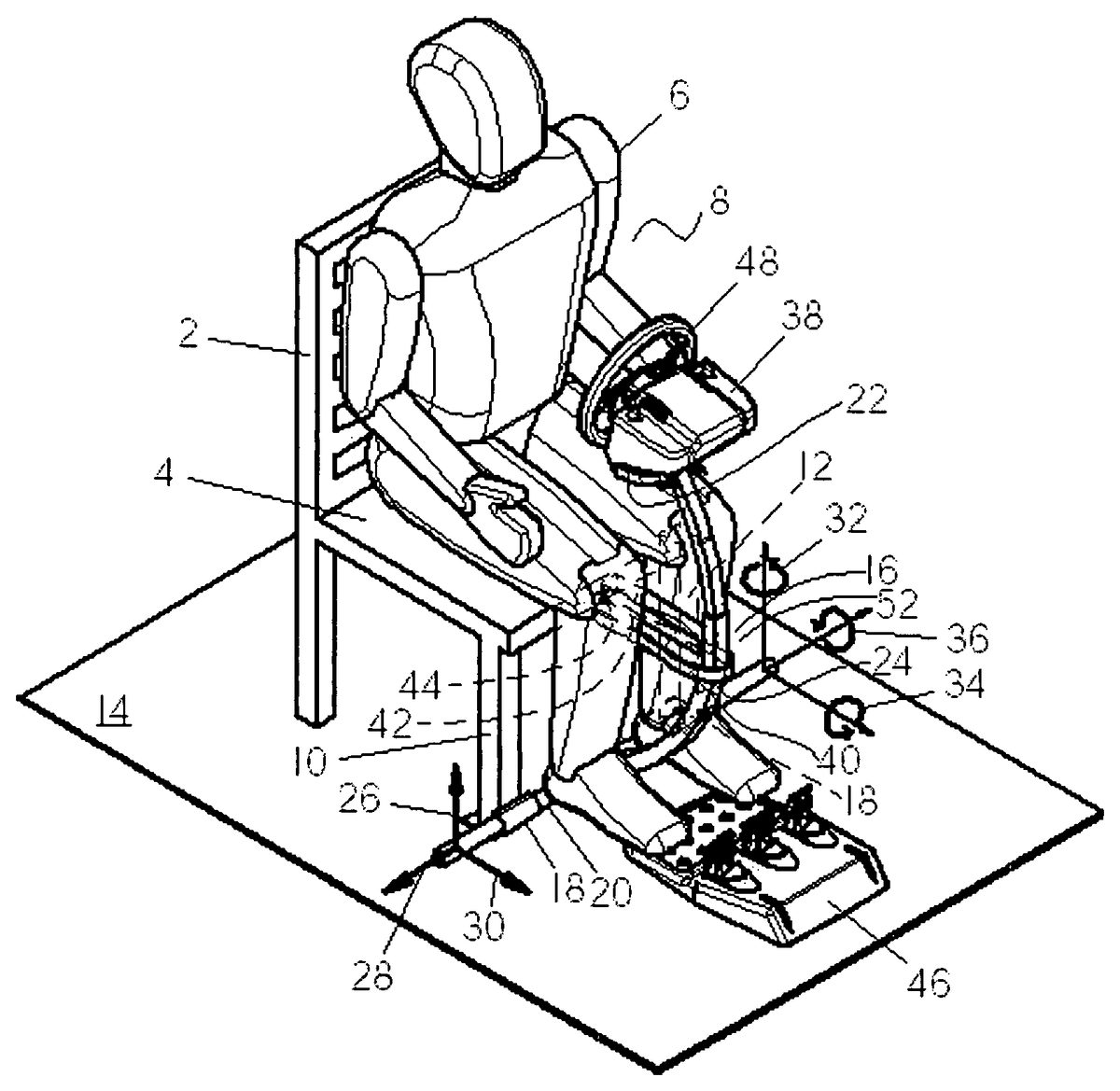
Referring toFIG. 1illustrating a portion of a video game user's play space, the present invention includes a chair2having a seat4for a user6and at least two legs10and12positioned on a floor14. The video controller stand16is secured to the chair2with a bracket18through which a rod20passes. The stand16is positioned in the playing position8. A controller mounting pad22is connected to the rod20with an upright24therebetween. For the combined rod20and upright24there are three axes of translation26,28, and30and three axes of rotation32,34, and36. A video game controller38may be mounted on the mounting pad22. In certain embodiments, a selectively securable band40, such as a hook and loop strap with a spacer block42is connected to the chair2at about seat height using a screw44attached to the seat4. The band40wraps around the upright24at a securing point intermediate between the ends of the upright24and fastens to itself. The spacer block42may limit the range of rotation in the backward direction towards the chair2. It is understood that other means for limiting the range of rotation such as contacting the seat4of the chair2or snapping into a C-section (not shown) may be used without violating the spirit of the present invention. An optional foot pedal controller46may be present for additional controls for the video game. In the presence of the foot pedal controller46, the user may remove his or her feet from the floor without impacting the stability of the video game controller stand16.
It should be further understood that the bracket18may be located on other parts of the chair2. Non-limiting examples of the bracket18may include using fasteners to connect the rod20directly to the chair2, incorporating a C-section to receive the rod20into a blow-molded chair base, or making a hole through the chair legs. In addition, the bracket may comprise one or more units, possibly connected to one another.
Further, the combination of the bracket18, rod20, and upright24may be made as a single unit or multiple articles. Examples are illustrated below.
Positioning the user6on the seat4puts the user's6weight on the chair legs10and12securing the bracket18and rod20in all three of the axes of motion26,28, and30, and two of three axes of rotation32and34allowing the user6to keep the video game controller steering wheel48in a relatively fixed position. With the band40attached, the third axis of rotation36becomes constrained and relatively fixes the video game controller stand16in space.
The present invention may fix the controller within a range of rotation and/or translation of five axes. The ranges may be independently selected from 2, 5, 8, or 10 to 12, 15, or 20 degrees of rotation of axes32and34; and ⅛, ¼, or ½ to 1, 2, or 4 inches of translation in the three axes26,28, and30. Further, rotation about the sixth axis36may be independently selected from 5, 10, 15, or 20 degrees to 25 or 30 degrees of rotation when in the playing position8. When the game is completed, the upright24may be rotated 30, 45, 60, or up to 90 degrees away from the user6to an inactive position (not shown) allowing the user6to easily exit the seat2.
WhileFIG. 1illustrates the upright24with an outwardly curved bow52, it should be understood that the upright may include a three-bar or four-bar linkage and/or be straight, angled, hinged, recurved, S-curved, articulated, compound curved, or inwardly curved without violating the intent of the invention. Further, it should be understood that the upright24may be a single upright, a U-shaped upright and/or channel, or have a plurality of uprights without violating the spirit of the invention. Further, an end of the upright24may include at least one angled support (not shown). This support may be, for a non-limiting example, a radiused continuation of the upright24that extends approximately perpendicular to the upright24or may form obtuse angles relative to a vertically oriented axis of the upright body24. If an embodiment includes two angled supports, it may appear almost like a triangle when coupled with an anchor member such as the rod20when the rod20connects to lower ends of two opposed angled supports.
The controller mounting pad22may be fixed, rotate and/or translate relative to the upright24. The video game controller38may be secured to the controller mounting pad22by attachment means known in the industry. The mounting pad22, in certain embodiments, may be incorporated into the video game controller38.
The floor14may be comprised of a traditional house surface or other floor surfaces known in the art. It should be understood that the floor14may be covered with other surfaces such as carpet or linoleum without departing from the spirit of the invention. Further, the chair2may be connected to a separate base (not shown) which may be positioned on the floor14without departing from the spirit of the invention.
Referring now toFIG. 2, a gaming chair70, a non-limiting example of which is an AK ROCKER Model 200 by AK Designs (Bluffdale, Utah), may be fitted into a gaming chair base72. The base72supports the downstanding columns74and the rocker76of the gaming chair70. The base72has a receiving cavity78incorporated into the bottom side80of the base72, which is adjacent to the floor82. Pivotably connected into the receiving cavity78is a connector84, such as a rod or a curved bar, which connects to a pin hitch86approximately at the midpoint of the connector. The pin hitch86pivotably connects to an extensible post88which connects the connector84with the controller mounting pad90which supports the video game controller92. The extensible post88may allow for the controller92to be positioned to the user's height for good ergonomic comfort. Further, the extensible post88may be curved outwardly94to allow the game controller to be positioned more closely to a player in the game playing position96. The extensible post88may be secured in the game playing position96using a catch98built into the pin hitch86. The catch98may be released by turning the handle100to activate a cable (not shown) or similar device connecting the handle100and the catch98. When released, the extensible post88may pivot in the forward direction102to a non-playing position104so that the user may exit the gaming chair70with relative ease.
The extensible post may be made compact for storage by shortening the post. Examples of the shortening or extending mechanism are well known in the art and may include, in a non-limiting sense, snap fits, spring loaded ball and socket combinations, or telescoping mechanisms.
The extensible post88may be comprised of relatively rigid materials and forms. Examples of forms may include a solid beam, an articulated arm, or a hollow tube. Typical materials may include thermoplastic plastic, thermoset plastic, or metal such as aluminum, white metal, or alloys including aluminum, copper, or zinc. In addition, the extensible post may be formed in multiple sections, a single homogeneous section or a single composite section. It should be understood that the various components of the extensible post, if any, may be comprised of one or more materials, including some relatively soft materials coated over a rigid section. It may be advantageous to have such overcoating of soft materials such as thermoplastic polyurethane to protect the user and to provide a comfortable touch and feel to the post88.
The base72may be designed to allow room for comfort if the user's feet are tucked under the gaming chair slightly. This is facilitated by placing the connector84further under the base72and extending only the pin hitch86.
It should be understood that the extensible post88may be connected directly to the connector84without violating the spirit of the present invention.
The base72may be relatively light in weight to facilitate movement for storage. Examples of such light construction may be accomplished by forming an essentially hollow base. Examples of non-limiting methods for forming these essentially hollow bases may include blow-molding, preparing hand layup composites, twin-sheet thermoforming or rotomolding such bases. It should be understood that the base may be fabricated in one or more sections. If more than one section is used, the base may be assembled. The sections may use one or more materials.
Typical materials for such processes may include thermoplastics, including polyolefin, polyvinyl chloride, long fiber thermoplastic, and polyalkylene terephthalate; or thermosets, including polyester, fiberglass reinforced polyester, or polyurethane.
Referring toFIG. 3, a gaming chair148such as an Ultimate Gaming Chair (Antioch, Calif.) or the Gaming Base (Corbeau LLC, Bluffdale, Utah) having four legs150,152,154, and156comprised of a ferrous material, connects magnetically to a rotatable ball-and-socket joint158disposed on at least one of front leg154, and optionally, a second front leg156. The joint158connects to a tube160and is secured to the leg154as well as selectably connects to the leg156, when in the playing position162. The tube160may be disconnected from leg156and swung aside on the ball-and-socket joint158when the player exits the gaming chair148and the video controller stand164is placed in the exiting/entry position (not shown).
It should be understood that the tube160and connection to the ball-and-socket joint158may be sufficiently rigid in the translational and rotational directions,166,168,170and172,174,176, respectively, that securing the tube160to another leg156of the gaming chair148, may not be needed to relatively fix the video game controller in space.
In using the video game controller stand, the user will connect the stand to the fixture to hold the stand adjacent to the chair. This fixture may include, but is not limited to, the bracket, the C-channel in the gaming chair base, or holes in the legs of the chair. Depending upon the fixture used, the video game controller stand may be slid into place, connected by an interference fit, mechanically secured, or other attachment means known in the art. In the exit position, the video game controller stand is typically in contact with the floor or an optional stand in contact with the floor. The user takes the position in the seat and draws the video game controller stand off of the floor and towards the seat. As an option, the user connects the video game controller stand to the seat either in a rigid or a flexible manner. The video game controller stand including the steering device for the video game and an optional video game screen are now relatively fixed in space. The user may then play the game and have good control of the positioning of the steering device in space. After completing the game, the user may optionally detach the video game controller stand from the seat and lower the stand towards the floor. Once the video game controller stand is in the exit position, the user may get up from the chair and leave the area.
Example 1
In this example, the video game controller stand is fabricated using ½″ diameter steel pipe that has a tensile strength in excess of 55,000 psi when tested according to ASTM D638 at 73° F. When the video game controller stand is connected to the AK ROCKER Model 100 seat using small blocks with brackets under the front ends of the rocker, and is secured to the seat using VELCRO hook-and-loop connectors fastened to the seat, the motion of the steering wheel is limited to about 10° of rotation or 2 inches of translation from the center position. A test user indicates that this amount of constraint allows adequate control of the steering device for the game.
Counter Example 1
In this example, the video game controller stand is fabricated using 2″ diameter Schedule 40 PVC pipe that has a tensile strength of 5300-8050 psi when tested according to ASTM D638 at 73° F. When the video game controller stand is connected to the AK ROCKER Model 100 seat using small blocks with brackets under the front ends of the rocker, and is secured to the seat using VELCRO hook-and-loop connectors fastened to the seat, the motion of the steering wheel moves at least about 20° of rotation or 5 inches of translation from the center position. In this condition, the game becomes uncontrollable in the opinion of the test user.
While the best mode for carrying out the invention has been described in detail, those familiar with the art to which this invention relates will recognize various alternative designs and embodiments for practicing the invention as defined by the following claims.
Claims
- A stand for a video game controller positionable on a floor, the stand comprising: a seating device having a seat;an anchor member selectably, operably connected to the seating device and spaced apart from the seat;an elongate upright member selectably connected to the seating device, the anchor member being connected to the upright member, the elongate upright member having a first end adjacent to the seating device, a second end opposed to the first end, and an attachment position therebetween, the first end being adjacent to the anchor member and the seat being connected to the upright member at the attachment position;and a platform connected to the upright member adjacent to the second end of the elongate upright member;wherein the anchor member permits rotation in a forward direction of the upright member and the platform.
- The stand of claim 1 , wherein the anchor member includes a base cooperable with the seating device.
- The stand of claim 2 , wherein the base defines a cavity adapted to receive a rod connected to the elongate upright member.
- The stand of claim 1 , wherein the elongate upright member is slidingly extensible.
- The stand of claim 1 with a video game controller, wherein the controller includes a motor providing force feedback to a steering device, the steering device being operatively connected to the platform.
- The stand of claim 1 , wherein the seating device includes a front edge having a channel open to the front edge, the channel adapted to receive the elongate upright member and limit the rotation of the upright member in the direction toward the seat.
- The stand of claim 1 , wherein the anchor member includes a bracket.
- The stand of claim 7 , wherein the bracket is adapted to receive a rod connected to the elongate upright member.
- The stand of claim 8 , wherein the seating device is a chair having at least two legs, the bracket being secured to at least one leg.
- The stand of claim 1 , wherein the elongate upright member includes a lower end having a first angled support and a second angled support, the angled supports being opposed and disposed at obtuse angles relative to the elongate upright member and securing the upright member to the anchor member.
- A stand for a video game controller positionable on a floor, the stand comprising: a seating device having a seat having a front end and a rear end, at least two legs, and a securing device adjacent to the front end of the seat;an upright member operably connected to the seating device at an elevation below the seat, the upright member being disposed at a position intermediate between the two legs when the upright member is in a playing position, the upright member being rotatable from an exiting position to the playing position, wherein the upright member is selectably securable to the securing device in the playing position;and a platform connected to the upright member and adapted for attaching a video game screen and a steering device of a video game controller.
- The stand of claim 11 , wherein the upright member has at least one angled section directed toward at least one leg of the seating device.
- The stand of claim 12 , wherein the leg of the seating device has an aperture and is adapted to be operatively connected to the angled section.
- The stand of claim 11 , wherein the upright member comprises a material having a tensile strength exceeding 8050 psi when tested according to ASTM D638 at 73° F.
- A stand for a video game controller positionable on a floor, the stand comprising: an upright member having at least one vertical member having a first top end and a first bottom end and a securing point intermediate between the first ends;at least one angled member having a second top end and a second bottom end, the second top end connected to the first bottom end, the second bottom end adapted to move about a first fixture sufficiently that the securing point cooperates with a second fixture when the upright member is moved between an exiting and a playing position, the first fixture being operably connected to the floor, the second fixture being elevated above the first fixture;and a platform connected to the first top of the upright member and adapted for operably connecting with a steering device of a video game controller.
- The stand of claim 15 , wherein the first fixture comprises a gaming chair.
- The stand of claim 15 , wherein the angled member is disposed approximately perpendicular to the upright member.
- The stand of claim 15 , wherein the second fixture includes a hook-and-loop strap.
Disclaimer: Data collected from the USPTO and may be malformed, incomplete, and/or otherwise inaccurate.