U.S. Pat. No. 7,849,491
APPARATUS AND METHOD FOR WIRELESS VIDEO GAMING
AssigneeOnLive, Inc.
Issue DateDecember 10, 2002
Illustrative Figure
Abstract
Apparatus for video gaming includes a box having a slot with an interface that connects to a game card providing a platform to run a software video game. The game card outputs video game data through the interface at a data rate of approximately 200 Mbps or greater. A unit processes the video game data for output to a display device. A wireless transceiver is included to receive the software video game via a wireless local area network (WLAN) and to transmit game information to a remote player having access to the WLAN during interactive play of the software video game. It is emphasized that this abstract is provided to comply with the rules requiring an abstract that will allow a searcher or other reader to quickly ascertain the subject matter of the technical disclosure. It is submitted with the understanding that it will not be used to interpret or limit the scope or meaning of the claims.
Description
DETAILED DESCRIPTION The present invention provides a system in which video games may be widely distributed and played without the need for multiple platform-specific hardware units or purchase of an optical disk to play a particular video game. According to the present invention, a wireless network is created for distribution of video games and interactive game playing. Individuals receive games and participate in playing video games utilizing a device (e.g., television, PC, set-top box, etc.) equipped to be compatible with a universal game platform architecture. In the following description numerous specific details are set forth, such as frequencies, circuits, configurations, etc., in order to provide a thorough understanding of the present invention. However, persons having ordinary skill in the satellite, communication and video gaming arts will appreciate that these specific details may not be needed to practice the present invention. It should also be understood that the basic architecture and concepts disclosed can be extended to a variety of different implementations and applications. Therefore, the following description should not be considered as limiting the scope of the invention. With reference toFIG. 1, a conceptual diagram of a satellite communication system in accordance with one embodiment of the present invention is shown comprising a telecommunications satellite12positioned in a fixed, geosynchronous orbital location in the sky over the particular geographical region of the Earth. Satellite12utilizes standard solar panels to generate power for the satellite's resources which includes one or more transponders that provide telecommunication links (i.e., “uplinks” and “downlinks”) to Earth-based stations and receivers. For example,FIG. 1shows a large antenna10that broadcasts video programs from an uplink center to satellite12. This uplink signal is represented by arrow11a. Satellite12transmits the broadcast signal (e.g., downlink11b) across a coverage region of the Earth, where it may be received at a home14equipped with an outdoor antenna assembly ...
DETAILED DESCRIPTION
The present invention provides a system in which video games may be widely distributed and played without the need for multiple platform-specific hardware units or purchase of an optical disk to play a particular video game. According to the present invention, a wireless network is created for distribution of video games and interactive game playing. Individuals receive games and participate in playing video games utilizing a device (e.g., television, PC, set-top box, etc.) equipped to be compatible with a universal game platform architecture.
In the following description numerous specific details are set forth, such as frequencies, circuits, configurations, etc., in order to provide a thorough understanding of the present invention. However, persons having ordinary skill in the satellite, communication and video gaming arts will appreciate that these specific details may not be needed to practice the present invention. It should also be understood that the basic architecture and concepts disclosed can be extended to a variety of different implementations and applications. Therefore, the following description should not be considered as limiting the scope of the invention.
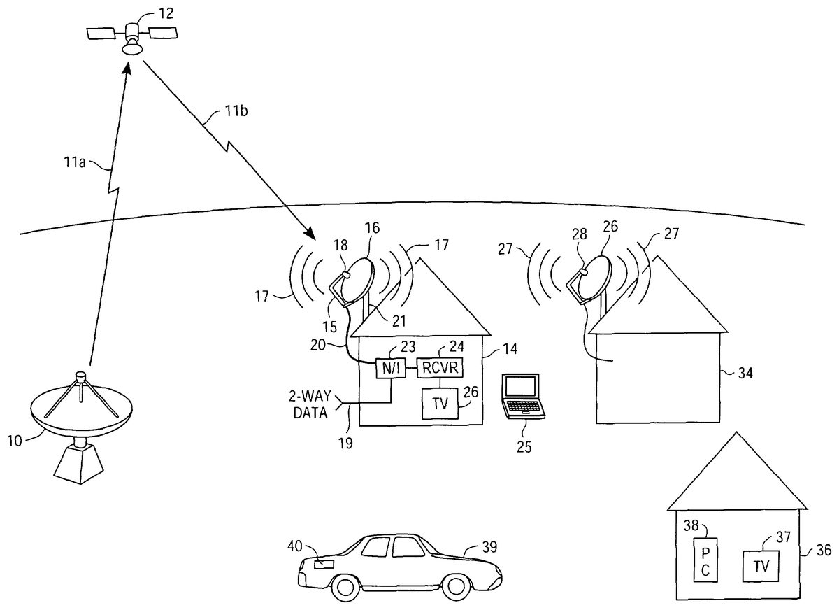
With reference toFIG. 1, a conceptual diagram of a satellite communication system in accordance with one embodiment of the present invention is shown comprising a telecommunications satellite12positioned in a fixed, geosynchronous orbital location in the sky over the particular geographical region of the Earth. Satellite12utilizes standard solar panels to generate power for the satellite's resources which includes one or more transponders that provide telecommunication links (i.e., “uplinks” and “downlinks”) to Earth-based stations and receivers.
For example,FIG. 1shows a large antenna10that broadcasts video programs from an uplink center to satellite12. This uplink signal is represented by arrow11a. Satellite12transmits the broadcast signal (e.g., downlink11b) across a coverage region of the Earth, where it may be received at a home14equipped with an outdoor antenna assembly coupled to electronics for displaying the video programs. The antenna assembly, which is also shown inFIG. 2, includes a support21attached to a parabolic or concave reflector dish16, which is aimed to the location in the sky where satellite12is positioned in geosynchronous orbit above the earth. Support21may include a base plate13to facilitate mounting of the antenna assembly to the exterior (e.g., roof) of house14. An arm15, attached to either dish16or support21, extends to position a signal unit18at a focal point of the reflector dish16. An antenna77for wireless transmissions is also shown attached to unit18. Unit18converts the electromagnetic radiation reflected from dish16into electrical signals carried by one or more conductors20to a network interface unit23or satellite receiver24within home14. Receiver24, for example, converts the satellite transmission signals into a format for display on television26.
With reference toFIG. 3, there is shown an exemplary embodiment of signal unit18in accordance with the present invention comprising a pair of lownoise block converters (LNBs)72&73and a wireless transceiver71mounted in a case or housing76. Wireless transceiver71has an associated antenna77to effectuate wireless transmissions. Feed horns74and75associated with LNBs72&73, respectively, protrude from a side of housing76that is positioned nearest to reflector dish16. Alternatively, the signal unit18may utilize a single feed horn coupled to one or more LNBs. Other embodiments may include multiple transceivers, each having its own associated wireless antenna. For instance, an alternative embodiment may comprise a pair of LNBs with an associated pair of wireless transceivers, each having its own wireless antenna.
In this example, LNBs72&73may be configured to receive horizontally and vertically polarized satellite transmission signals. Cable20connects with the LNBs and transceiver71. (It should be understood that within the context of this disclosure, the term “cable” is used to refer to one or more wires and that such wires may comprise coaxial wires of a type known as RG-6, or a similar type.)
It is appreciated that in other embodiments unit18may comprise a single LNB and a wireless transceiver. In still other embodiments, unit18may include four or more LNBs and one or more wireless transceivers mounted together.
According to one embodiment of the present invention, wireless transceiver71operates in compliance with IEEE specification 802.11a, 802.11b, 802.11g, etc., to provide high-speed networking and communication capability to computers, televisions, and other devices compatibly equipped to receive such wireless signals. Other embodiments may operate in compliance with variant specifications that are compatible with IEEE specification 802.11a, 802.11b, or 802.11g, and which provide for wireless transmissions at high-bandwidth video data rates (e.g., about 2 Mbps or greater). For the purposes of the present application, IEEE specification 802.11a, 802.11b, 802.11g, and Industrial, Scientific, and Medical (ISM) band networking protocols are denoted as “802.11x”. Other non-ISM bands wireless network protocols could be utilized as well. Transceiver71facilitates network connectivity to users located within a surrounding range, allowing them to receive satellite broadcast programs, pay-per-view services, on-demand video, Internet access, and other interactive data services, thus obviating the need for a wired connection to individual users.
In the example ofFIG. 1, transceiver71operates over the license-free 5 GHz band (e.g., 5725 MHz to 5850 MHz) to provide upwards of 54 Mbps of bandwidth in good transmission conditions. IEEE specification 802.11a allows for a high-speed wireless transmission of raw data at indoor distances of up to several hundred feet and outdoor distances of up to ten miles, depending on impediments, materials, and line-of-sight. 802.11a has twelve channels (eight in the low part of the band for indoor use and four in the upper for outdoor use) which do not overlap, allowing for dense installations. According to the present invention, individual users may receive transmissions from transceiver71using hardware equipment available from a number of vendors. For example, Proxim, Inc. manufactures and sells the Harmony 802.11a PCI card that provides wireless broadband networking at a data rate of 54 Mbps.
In another embodiment, transceiver71operates in compliance with IEEE specification 802.11g over the license-free 2.46 GHz band.
As shown inFIG. 1, wireless signals17may be transmitted from unit18of the antenna assembly mounted on house14to a nearby laptop computer25installed with a PC card or a PCI card that is 802.11x compliant. Similar equipment may be installed into slots of a personal computer38or a television37to provide connectivity to network services in a house36that is located within the neighboring range of the wireless transceiver, despite the fact that house36does not have a satellite antenna dish or is not otherwise wired to receive such services. This means, for example, that someone may access their electronic mail from any location within the full extent of the wireless network since the transmission signals pass easily through walls and glass.
In the example ofFIG. 1, house36may be located outside of the signal range of wireless transmission signals17, but within the range of the wireless signals27from the transceiver mounted in unit28of antenna assembly26on top of a neighboring house34. In such a case, the transceiver within unit28may function as a repeater or hub for house-to-house transmissions; that is, to relay the media content and interactive services provided at home14to users at home36and elsewhere. Through the use of transceivers71functioning as repeaters, content and two-way data services may be distributed to end users located at considerable distances from the original service connection source. In other words, a neighborhood of antenna assemblies that include wireless transceivers can be used to create a network that provides distributed video program and interactive data connectivity. Homes installed with an antenna assembly according to the present invention may still act as a house-to-house repeater for the neighborhood as part of a “roof-hopping” scheme, even though they may not have an immediate need for wireless communications, Later on, those homes may simply add the appropriate hardware (e.g., wireless communication card, network interface box, etc.) to take advantage of the additional services such as interactive data provided by wireless connectivity.
It should be understood that according to the present invention, the individual satellite antenna assemblies need not be located on homes or other buildings; instead, they may be positioned on existing telephone poles, or mounted on other structures with dedicated, stand-alone hardware. Additionally, stand-alone wireless transceivers that function solely as signal repeaters may be physically distributed in a geographic region or throughout a large building wherever power is available to provide network connectivity that extends throughout the region or area.
FIG. 4, for example, shows a large apartment building50with a satellite antenna assembly that includes a reflector dish56and a wireless transceiver mounted in signal unit58. (The electronics that provides power and command/control signals for the antenna assembly is not shown inFIG. 4for clarity reasons.) A series of repeaters60a-60eare located on various floors throughout the building to distribute signal transmissions to/from the transceiver of unit58to each of the multiple apartment units within building50. A two-way data service connection (e.g., DSL) is provided to an 802.11x wireless transceiver/repeater60e. Thus, subscribers located anywhere within building50may connect to the DSL service via this wireless transmission. Similarly, two-way data service connectivity is provided to others within the range of the transceiver of unit58of the antenna assembly mounted on the roof of building50(or to anyone in a neighboring region reached via roof-hopping signal repeating). In a metropolitan region a single satellite antenna assembly with integrated wireless transceiver can therefore distribute high bandwidth services to residents of neighboring buildings, even though those neighboring buildings may not have a satellite antenna or be otherwise wired to receive those services.
Additionally, wireless transceiver/repeater60emay be connected to receive video content from some media source, e.g., a Digital Versatile Disk (“DVD”) player, or cable television programming. In the later case, for instance, wireless transceiver/repeater60emay include a cable modem equipped with an 802.11x transmitter. These alternative or additional services may then be distributed in a similar manner described above.
FIG. 1also illustrates another extension of the network provided by the present invention, wherein media content may be distributed to an 802.11x compliant receiver unit40installed in the trunk of an automobile39, or other mobile vehicle. Unit40, for instance, may include a hard disk drive to store video programs received from wireless transmission signals17when automobile40is parked, say, overnight in a garage. These programs can then be viewed by rear-seat passengers on a trip the following day.
With continued reference to the example ofFIG. 1, two-way data service is shown being provided by cable19connected to a network interface unit23. Cable19may provide a direct subscriber line (DSL) connection, for instance, which may then be distributed to subscribers in the surrounding range of wireless signals17. Thus, according to the present invention a user of laptop computer25, who may be located outdoors or at a nearby cafe, can access the Internet, watch a pay-per-view film, or receive a multitude of other multimedia services.
Alternatively, network interface unit23may be connected to a cable broadcast service provider (e.g., cable television) through an Ethernet or Universal Serial Bus (USB), or similar connection, thereby enabling wireless access of those cable services to subscribers within the range of the wireless network. This means that a subscriber may watch their favorite television program or a pay-per-view movie from a laptop computer or television while outdoors, in a cafe, or in some other building, within the wireless coverage region without the need for a direct-wired cable connection. Distribution of cable services may be implemented with a cable modem device that includes an 802.11x transmitter. It is appreciated that additional circuitry for encrypting the video and data information may also be included to thwart pirates and interlopers.
Network interface unit23provides power to and communicates with transceiver71of unit18via cable20. Although the embodiment ofFIG. 1shows network interface unit23connected to satellite receiver24, alternatively both devices may be integrated in to a single device30, as shown inFIG. 6. In either case, the network interface unit communicates with the transceiver using spectrum that is not otherwise utilized in cable20. Since satellite receivers tend to operate in the spectrum from about 1.2 GHz to about 2 GHz, the spectrum below 1.2 GHz, down to about 40 MHz, may be used for communications with the wireless transceiver. This spectrum band is illustrated inFIG. 5.
It should also be understood that althoughFIG. 1shows a direct connection between satellite receiver24and television26, alternatively, video services may be provided to any 802.11x compliant television (e.g., installed with an 802.11x adapter card) located within the house or surrounding wireless coverage region.
FIG. 6depicts the type of information and signals carried by cable20between network interface/satellite receiver device30and unit18of the antenna assembly of the present invention. Many techniques are well known in the electronics and communications arts for transmitting such signals, such as QPSK and QAM modulation. As shown, satellite signals received by the antenna assembly are provided to device30via cable20. Additionally, wireless transmissions received by transceiver71are coupled to device30. Device30provides power to the LNBs and transceiver, LNB configurations signals, transceiver command and control signals, and wireless data via cable20. By way of example,FIG. 6shows device30having a DSL connection that may provide Internet access to users within the surrounding range of the transceiver of unit18.
FIG. 7illustrates the MDU example ofFIG. 4, but with a specialized mass storage repository unit64installed on the rooftop of building50. Repository unit64comprises a number of hard disk drives (HDDs) having a large total storage capacity (e.g., 10 terabytes) arranged as a RAID (“Redundant Array of Inexpensive Disks”)65that functions as a media library apparatus. An 802.11x compliant wireless transceiver66is also included in repository unit64along with various electronics67coupled to both RAID65and transceiver66. Electronics67may comprise a microcomputer including a processor (CPU), a ROM, a RAM, etc., to control the data read/write processing by the HDDs and to control the operation of transceiver66. Electronics67may also include data compression/decompression circuitry for certain video and data applications. Still other embodiments may include encryption/decryption circuitry for receiving and sending transmissions in a secure manner. The RAID65, transceiver66, and electronics67are all housed in rugged, weather-resistant enclosure providing a suitable environment for the HDDs and the other circuitry.
Repository unit64may communicate via wireless transmission utilizing wireless transceiver66connected to a wireless antenna68mounted on top of unit64. Alternatively, unit64may be coupled with signal unit58via a wire connection69(e.g., CAT-5) to utilize the transceiver in signal unit58for wireless communications.
In an alternative embodiment, repository unit64may be attached to the satellite antenna assembly to directly utilize the wireless transceiver installed in signal unit58.
The purpose of RAID65is to store recorded media content (e.g., pay-per-view movies, videos, DVDs, special event programs, etc.). This content can be accumulated over time in a “trickle feed” manner from wireless transceiver66, which may receive content from various sources such as satellite transmissions, media players, cable television, Internet, etc. Over time, repository unit64may store such large volumes of video programming. Anyone having the capability to access the wireless network can pay a fee to receive a particular show, movie, or viewable program stored in repository unit64on an on-demand basis.
Additionally, because of the interactive capabilities of the wireless network, the subscriber or user may communicate with unit64to provide commands such as “pause”, “fast forward”, “rewind”, etc. Indeed, because of the large storage space available, live broadcast programs available through the WLAN described previously may be manipulated using such commands, thereby providing enhanced viewing flexibility to the user. Hard disk drive failures, which often plague in-home digital video recorders (DVRs), are not a problem because of the redundancy protection built into the RAID. Should a particular hard disk drive fail during operation, the remaining disk drive units simply take over until the repository unit can be serviced, at which time the failed drive can be replaced.
Repository unit64may also function as an archive storage apparatus for individuals within a local area to utilize as a storage facility for back-ups of personal data. For example, personal data such as photographs, important documents, books, articles, etc. may be transferred into a reserved space in the RAID. Various well-known security features may be built into repository unit64to maintain personal security of the backed-up data for each user.
It is also appreciated that repository unit64may be physically located somewhere other than on the rooftop of a building of MDUs. For instance, instead of being attached to, or nearby, a rooftop antenna assembly, repository unit may be located in a top floor space, in a basement, or in a ground level facility.
FIG. 9is a circuit block diagram of a game card120that provides a universal game platform that can be inserted into a slot of a compatible electronic device, such as the set-top box90shown inFIG. 10. In one embodiment, game card120may comprise a high-bandwidth PCMCIA or PC card manufactured in accordance with a universal standard approved by game software developers. This allows game card120to run any game developed by a software game developer in compliance with the universal standard. The video games may be downloaded directly to set-top box90via wired or wireless transmission, thus obviating the need to purchase an optical disk for each video game. This aspect of the present invention is discussed in more detail below.
Game card120has the computing resources needed to support advanced, high-performance games, including a central processing unit (CPU)121, high-speed RAM122, and a high-performance 3-D graphics engine126. By way of example, CPU121, RAM122, and graphics engine126are shown coupled to high-speed bus124for transfer of instructions and data. Game card120couples with set-top box90via an interface132that includes command and control lines127, power lines130, and high-speed video and audio outputs128and129, respectively. Interface82provides full bandwidth video output rates. For example, in one embodiment game card120may run at a clock rate of about 12.27 MHz with 24-bits of color to provide video data at a rate of 288 Mbps.
FIG. 10is a detailed circuit block diagram that shows one embodiment of set-top box90that functions as a video game player according to the present invention. Set-top box90includes a slot85, which is coupled to bus91, for accepting game card120. Slot85provides a compatible interface connection with interface132of card120. Set-top box90also includes a CPU87, a relatively low-speed RAM94, and a graphics unit93, each of which is coupled to bus91. Graphics unit93produces video and audio outputs signals that may be coupled to a television, for example, or some other display unit suitable for playing a selected video game. CPU87, RAM94, and graphics unit93function to provide a user interface and a graphics path to a display screen for the playing of video games on the high-performance platform provided by game card120.
Video games may be downloaded in the embodiment ofFIG. 10utilizing a wireless transceiver88, which may operate as an 802.11x-compliant device. By way of example, video games may be downloaded from a broadband connection provided via a WLAN, as described previously. Alternatively, transceiver88may receive video games from a satellite transmission link, or a cable modem connection, via wireless transmission. Another possibility is to download games via wired transceiver89. Wired transceiver89may operate in compliance with Ethernet, DOCSIS, DSL, or other protocols.
In certain applications, set-top box90may optionally include a compression/decompression unit95coupled to bus91to compress video data prior to transmission, or to decompress video data after reception, via transceiver88.
Video games may be played interactively between first and second players using wireless transceiver88. The first player may provide input commands through a command/control module coupled to set-top box90. For example, set-top box90may include an infrared (IR) unit (not shown) to receive IR input command and control signals from a player located in the same room. The IR unit may be coupled to CPU87to process the player commands (e.g., movement buttons, joystick commands, etc.) received from a remote game controller unit. The second player may be located anywhere within the surrounding range of the WLAN (i.e., in a neighboring house or building).
Still another option is to include a DVD or CD-ROM drive in set-top box90for playing/loading software video games.
Practitioners in the art will appreciate that the combination of a specialized game card that provides a universal game platform with a compatible set-top box for downloading and playing specific games offers numerous advantages. For instance, since the graphics capabilities of video games tend to evolve at a much faster pace as compared to the set-top box (which may have a useful life of ˜8-10 years), each time the graphics platform evolves to accommodate a newer generation of games, the old game card may simply be swapped for the newer version. The new game card can be used to play the newer generation of games and the old card retained to play the previous generation games. Since the display path provided by the set-top box remains the same for the graphics generated across different generations of the game card, the set-top box does not need replacement or substitution.
In other instances, a person may purchase a set-top box that functions as a satellite receiver or as a digital cable receiver unit, but which is adapted with a slot for accepting a game card in accordance with the present invention. Initially, the person may not wish to utilize the box's game playing capability. However, when the person does desire to add game playing to his box, he may simply purchase a game card that provides the necessary computing capability and insert the card into the interface slot provided by the set-top box.
As a practical matter, it should be understood that due to the very high data rates involved, set-top box90may also include any of a number of well known heat-dissipation mechanisms, such as fans, vents, heat sinks, active cooling systems, and so on. Set-top box90may be equipped with a large power supply to furnish the power necessary for running high-performance video games. Alternatively, game card120may be configured with a rear power jack for connection to a dedicated power supply.
FIG. 11is a circuit block diagram of a video repository unit64that may function as a video game server in accordance with one embodiment of the present invention. In this embodiment, RAID65stores a library of video games that may be sent to a remote user via transceiver66. The remote user may also play interactive games with another user via wireless transmission through transceiver66.
In the embodiment ofFIG. 11, repository unit64is shown including a CPU101, a RAM103, and a disk controller unit102interconnected to RAID65as previously described. An optional video compression unit104is also shown. Video compression unit104provides low latency (i.e., <˜-80 ms) data compression of video for high “twitch-action” games (<150 ms for slower games). Video compression unit104may be coupled directly to a wired or wireless transceiver for transmission of game data. Also shown is a video game hardware unit106, which includes one or more high-performance video games that may be loaded to execute on a corresponding set of game cards, such as game card120described previously.
Configured in this manner, repository unit64functions as a video game server for remotely located players who may communicate commands and receive video data via wired or wireless transmissions with unit64. For example, one or more persons may submit a request to play a particular video game stored in the library of repository unit64. That game would then run on the game card installed in the repository unit, with the commands and video data transmissions being communicated between repository unit64and remote location(s) utilizing wireless or wired transceivers. In addition, repository unit64may also provide other media services (television, pay-per-view, on-demand programs, etc.) to persons in the surrounding area via wireless connection.
It should be further understood that although the present invention has been described in conjunction with specific embodiments, numerous modifications and alterations are well within the scope of the present invention. Accordingly, the specification and drawings are to be regarded in an illustrative rather than a restrictive sense.
Claims
- A method of operating a video game box comprising: downloading a software video game to a storage device via a wireless transceiver, the software video game being compliant with a game platform standard;running the software video game on a game card coupled to the video game box via an interface, the game card including a processor, a memory and a graphics engine, the game card providing a game platform compliant with the game platform standard, high twitch-action video game data being output through the interface;processing the high twitch-action video game data for output to a display device;compressing the high twitch-action video game data with a latency of less than approximately 80 ms, but greater than about 5 ms;wirelessly transmitting the compressed high twitch-action video game data to a remote player via the wireless transceiver during interactive play of the software video game, the remote player being located a distance beyond a transmission distance of the wireless transceiver.
- The method of claim 1 wherein the wireless transceiver operates in the 5 GHz band.
- The method of claim 1 wherein the wireless transceiver operates in compliance with IEEE 802.11x specification.
- A set-top box comprising: an interface that connects to a game card that provides a game platform to run a software video game, the game card including a processor, a memory and a graphics engine, the game card being operable to output high twitch-action video game data through the interface;a unit to process the high twitch-action video game data for output to a display device;a wireless transceiver to receive the software video game via a wireless network;a compression unit for compressing the high twitch-action video game data with a latency of less than approximately 80 ms, but greater than about 5 ms;and wherein the wireless transceiver is further operable to wirelessly transmit the compressed high twitch-action video game data to at least one remote user, and to receive commands from the at least one remote user, via the wireless network, the remote user being located beyond a transmission range of the wireless transceiver.
- The set-top box of claim 4 wherein the unit comprises: a central processing unit (CPU);a random-access memory (RAM) coupled to the CPU;and a graphics unit coupled to the CPU.
- The set-top box of claim 4 wherein the transceiver operates in the 5 GHz band.
- The set-top box of claim 4 wherein the transceiver operates in compliance with IEEE 802.11x specification.
- The set-top box of claim 4 wherein the wireless transceiver transmits game information to a remote player having access to the wireless network during interactive play of the software video game.
- The set-top box of claim 4 further comprising an infrared (IR) receiver to receive video game commands.
- A set-top box comprising: an interface that connects to a game card providing a game platform to run a software video game;a unit to process the video game video for output to a display device;a wireless transceiver to receive the software video game via a wireless local area network (WLAN) and to wirelessly transmit game information to a remote player having access to the WLAN during interactive play of the software video game;a compression unit for compressing the video game video with a latency of less than approximately 80 ms, but greater than about 5 ms;and wherein the wireless transceiver is further operable to wirelessly transmit the compressed video game video to at least one remote user, and to receive commands from the at least one remote user, via the WLAN, the at least one remote user being located beyond a transmission range of the wireless transceiver.
- The set-top box of claim 10 wherein the unit comprises: a central processing unit (CPU);a random-access memory (RAM) coupled to the CPU;and a graphics unit coupled to the CPU.
- The set-top box of claim 10 wherein the wireless transceiver operates in the 5 GHz band.
- The set-top box of claim 10 wherein the wireless transceiver operates in compliance with IEEE 802.11x specification.
- The set-top box of claim 10 further comprising an infrared (IR) receiver to receive video game commands.
- An apparatus comprising: a unit operable to execute at least one high twitch-action video game for one or more players, video game video being produced therefrom;a compression unit for compressing the video game video with a latency of less than approximately 80 ms, but greater than about 5 ms;and a transceiver operable to transmit the compressed video game video to, and to receive commands from, the one or more players, over a network, the one or more players being located a remote distance beyond a premises where the apparatus is located such that transmissions between the transceiver and the one or more players pass through at least one additional transceiver of the network.
- The apparatus of claim 15 further comprising an interface that connects to a game card providing a platform to run the at least one high twitch-action video game.
- The apparatus of claim 15 wherein the transceiver is further operable to receive the at least one high twitch-action video game from either a satellite communication link or a cable television service transmission link.
- The apparatus of claim 15 wherein the network comprises a wireless network.
- The apparatus of claim 15 wherein the transceiver comprises a wired transceiver.
- The apparatus of claim 15 wherein the transceiver comprises a wireless transceiver.
- An apparatus comprising: a unit that includes a processor operable to execute at least one high twitch-action video game, video game video being produced therefrom;a compression unit for compressing the video game video with a latency of less than approximately 80 ms, but greater than about 5 ms;and a wireless transceiver operable to transmit the compressed video game video, and receive commands from at least one remote player, over a network, the at least one remote player being located a distance beyond a first transmission range of the wireless transceiver, the network comprising a plurality of additional wireless transceivers geographically distributed in a region extending in a transmission chain from a point within the first transmission range of the wireless transceiver to the at least one remote player.
- An apparatus video game server comprising: a processing unit for executing a high twitch-action video game for one or more players, video game video being produced therefrom;a compression unit operable to compress the video game video with a latency of less than approximately 80 ms, but greater than about 5 ms;and a transceiver to transmit the compressed video game video to the one or more players of the high twitch-action video game over a network, the one or more players being located a remote distance from the apparatus such that transmissions between the transceiver and the one or more players pass through at least one additional transceiver of the network, the transceiver also being operable to receive commands from the one or more players over the network.
- The apparatus of claim 22 further comprising a Redundant Array of Inexpensive Disks (RAID) that stores the high twitch-action video game in a media library.
- The apparatus of claim 22 wherein the transceiver comprises a wired transceiver.
- The apparatus video game of claim 22 wherein the transceiver comprises a wireless transceiver.
Disclaimer: Data collected from the USPTO and may be malformed, incomplete, and/or otherwise inaccurate.