U.S. Pat. No. 7,833,100
VIDEO GAME PROGRAM AND VIDEO GAME SYSTEM
AssigneeNintendo Co., Ltd.
Issue DateApril 24, 2006
Illustrative Figure
Abstract
A video game device displays a reference image (an image of a fishing rod 54) at a predetermined position on the screen of a display device. The video game device displays a pointer image (a cursor 55) at a position on the screen being pointed at by a control device. The pointer image is erased when the pointer image reaches within a predetermined area defined based on the position of the reference image. The video game device controls the controlled object to act according to a position of a marker object in a captured image based on control data, after the pointer image reaches inside the predetermined area defined based on the position of the reference image.
Description
DESCRIPTION OF THE PREFERRED EMBODIMENTS First Embodiment Referring toFIG. 1, a video game system1, being an information processing system in one embodiment, will be described.FIG. 1shows an external view of the video game system1. In the present embodiment, the video game system1includes a home-console type video game device. Referring toFIG. 1, the video game system1includes a home-console type video game device (hereinafter simply “video game device”)3and a controller7for giving control data to the video game device3. The video game device3is connected, via a connection cord, to a display (hereinafter “monitor”)2provided with a speaker22, such as a home television receiver. Two markers8aand8bare provided around the monitor2(on the upper side of the screen in the illustrated example). Specifically, the markers8aand8bare infrared LEDs outputting infrared light to the front side of the monitor2. A receiver unit6is connected to the video game device3via a connection terminal. The receiver unit6receives control data wirelessly transmitted from the controller7, and the controller7and the video game device3are connected via wireless communications. The video game system1includes an optical disk4, being an example of an information storage medium that can be received by the video game device3. Provided on the upper principal plane of the video game device3are an ON/OFF switch for turning ON/OFF the power of the video game device3, a reset switch for resetting a game process, and an OPEN switch for opening the upper lid of the video game device3. The lid opens up when the OPEN switch is pressed by the player so that the optical disk4can be put in place. The video game device3can also receive an external memory card5including a backup memory, or the like, for statically storing save data, or the like. The video game device3executes a video game program, or the like, stored in the optical disk4to obtain a game image, and ...
DESCRIPTION OF THE PREFERRED EMBODIMENTS
First Embodiment
Referring toFIG. 1, a video game system1, being an information processing system in one embodiment, will be described.FIG. 1shows an external view of the video game system1. In the present embodiment, the video game system1includes a home-console type video game device.
Referring toFIG. 1, the video game system1includes a home-console type video game device (hereinafter simply “video game device”)3and a controller7for giving control data to the video game device3. The video game device3is connected, via a connection cord, to a display (hereinafter “monitor”)2provided with a speaker22, such as a home television receiver. Two markers8aand8bare provided around the monitor2(on the upper side of the screen in the illustrated example). Specifically, the markers8aand8bare infrared LEDs outputting infrared light to the front side of the monitor2. A receiver unit6is connected to the video game device3via a connection terminal. The receiver unit6receives control data wirelessly transmitted from the controller7, and the controller7and the video game device3are connected via wireless communications. The video game system1includes an optical disk4, being an example of an information storage medium that can be received by the video game device3. Provided on the upper principal plane of the video game device3are an ON/OFF switch for turning ON/OFF the power of the video game device3, a reset switch for resetting a game process, and an OPEN switch for opening the upper lid of the video game device3. The lid opens up when the OPEN switch is pressed by the player so that the optical disk4can be put in place.
The video game device3can also receive an external memory card5including a backup memory, or the like, for statically storing save data, or the like. The video game device3executes a video game program, or the like, stored in the optical disk4to obtain a game image, and displays the obtained game image on the monitor2. The video game device3may reproduce a past game status from save data stored in the external memory card5to obtain a game image for that past game status, and display the obtained game image on the monitor2. Then, the player of the video game device3can enjoy the game process by operating the controller7while watching the game image displayed on the monitor2.
The controller7wirelessly transmits, from a communications section36(to be described later) therein, the control data to the video game device3, to which the receiver unit6is connected, by means of a technique such as Bluetooth (registered trademark), for example. The controller7is means for controlling the controlled object (i.e., an object displayed on the monitor2). The controller7has a control section, including a plurality of control buttons. As will be more apparent from the following description, the controller7includes an image capturing/processing section35(described later) for capturing an image as viewed from the controller7. Specifically, the image capturing/processing section35takes an image of the markers8aand8bprovided around the monitor2. The video game device3uses the image to obtain a control signal corresponding to the position and orientation of the controller7.
Referring now toFIG. 2, a configuration of the video game device3will be described.FIG. 2is a functional block diagram showing the video game device3.
Referring toFIG. 2, the video game device3includes a RISC CPU (Central Processing Unit)10, for example, for executing various programs. The CPU10executes a boot program stored in a boot ROM (not shown), thus initializing memory devices, such as a main memory13, and then executes a video game program stored in the optical disk4to perform a game process, etc., according to the video game program. Connected to the CPU10via a memory controller11are a GPU (Graphics Processing Unit)12, the main memory13, a DSP (Digital Signal Processor)14, and an ARAM (Audio RAM)15. The memory controller11is connected, via a predetermined bus, to a controller I/F (interface)16, a video I/F17, an external memory I/F18, an audio I/F19and a disk I/F21, which are connected to the receiver unit6, the monitor2, the external memory card5, the speaker22and a disk drive20, respectively.
The GPU12is responsible for image processing based on instructions from the CPU10, and is a semiconductor chip, for example, capable of computations necessary for3D graphics display. The GPU12performs the image process by using a memory dedicated for image processing (not shown) or a part of the memory area of the main memory13. The GPU12produces game image data or movie data to be displayed on the monitor2using these memory areas, and outputs the produced data to the monitor2via the memory controller11and the video I/F17as necessary.
The main memory13is a memory area used by the CPU10, and stores a video game program, etc., as necessary for processes performed by the CPU10. For example, the main memory13stores the video game program loaded from the optical disk4by the CPU10and various data, etc. The video game program, the various data, etc., stored in the main memory13are executed or processed by the CPU10.
The DSP14is for processing sound data, etc., produced by the CPU10when executing the video game program, and is connected to the ARAM15for storing the sound data, etc. The ARAM15is used when the DSP14performs a predetermined process (e.g., storing a video game program, sound data, etc., which have been loaded in advance). The DSP14reads out the sound data stored in the ARAM15, and outputs the sound data through the speaker22provided in the monitor2via the memory controller11and the audio I/F19.
The memory controller11is responsible for the overall control of data transfers, and is connected to the various I/F's described above. The controller I/F16includes, for example, four controller I/F portions, each having a connector into which an external unit can be fitted for communicable connection between the external unit and the video game device3. For example, the receiver unit6may be fitted into the connector to be connected to the video game device3via the controller I/F16. As described above, the receiver unit6receives control data from the controller7, and outputs the control data to the CPU10via the controller I/F16. In other embodiments, the video game device3may include therein, instead of the receiver unit6, a receiver module for receiving control data transmitted from the controller7. In such a case, the transmitted data received by the receiver module is outputted to the CPU10via a predetermined bus. The monitor2is connected to the video I/F17. The external memory card5is connected to the external memory I/F18, whereby a backup memory, etc., provided in the external memory card5can be accessed. The audio I/F19is connected to the speaker22provided in the monitor2so that the sound data read out from the ARAM15by the DSP14or the sound data outputted directly from the disk drive20can be outputted through the speaker22. The disk I/F21is connected to the disk drive20. The disk drive20reads out data from the optical disk4placed in a predetermined read-out position, and outputs the data to the bus or the audio I/F19of the video game device3.
Referring now toFIGS. 3A to 7, the controller7will be described.FIGS. 3A to 5Bare perspective views showing the external structure of the controller7.FIG. 3Ais a perspective view showing the controller7as viewed from the upper rear side, andFIG. 3Bis a perspective view showing the controller7as viewed from the lower rear side.FIG. 4shows the controller7as viewed from the front side.
The controller7shown inFIGS. 3A,3B and4includes a housing31formed by molding a plastic material, for example. The housing31has a generally rectangular parallelepiped shape, with the longitudinal direction being the front-rear direction (the Z-axis direction shown inFIG. 3A), and has an overall size such that it can be held in a hand of an adult or a child. The player can use the controller7for game operations by pressing buttons provided on the controller7and by changing the position and direction of the controller7itself. For example, the player can make the controlled object move by turning the controller7about an axis in the longitudinal direction. The player can move an object in the game space by changing the position on the screen pointed at by the controller7. As used herein, “the position on the screen pointed at by the controller7” is ideally the position at which the straight line extending in the longitudinal direction from the front end of the controller7crosses the screen of the monitor2. However, it does not have to be precisely the position as long as a position in the vicinity thereof can be calculated by the video game device3. Hereinafter, the position on the screen pointed at by the controller7will be referred to as the “pointed position”. Moreover, the longitudinal direction of the controller7(the housing31) may hereinafter be referred to as the “pointing direction of the controller7”.
The housing31includes a plurality of control buttons. Provided on the upper surface of the housing31are a cross-shaped key32a, an X button32b, a Y button32c, a B button32d, a select switch32e, a menu switch32fand a start switch32g. A depressed portion is formed on the lower surface of the housing31, and an A button32iis provided on a slope on the rear side of the depressed portion. Each of these buttons (switches) is assigned a function as specified in the video game program executed by the video game device3, the details of which will not be discussed herein as being not directly related to the description of the present invention. A power switch32hfor turning ON/OFF the power of the video game device3from a remote position is provided on the upper surface of the housing31.
Moreover, the controller7includes the image capturing/processing section35(FIG. 5B), and a light receiving port35aof the image capturing/processing section35is provided on the front side of the housing31as shown inFIG. 4. A connector33is provided on the rear side of the housing31. The connector33is, for example, a 32-pin edge connector, and may be used for connecting other units to the controller7. Moreover, a plurality of LEDs34are provided on the upper surface of the housing31near the rear end. The controller7is given a controller ID (number) for identifying the controller7from others. The LEDs34are used for notifying the player of the controller ID being currently assigned to the controller7. Specifically, when control data is transmitted from the controller7to the video game device3, one of the LEDs34is lit depending on the controller ID.
Referring now toFIGS. 5A,5B and6, an internal configuration of the controller7will be described.FIGS. 5A and 5Bshow an internal configuration of the controller7.FIG. 5Ais a perspective view showing the controller7with an upper casing (a part of the housing31) taken off.FIG. 5Bis a perspective view showing the controller7with a lower casing (a part of the housing31) taken off.FIG. 5Ashows one side of a substrate300, andFIG. 5Bshows the other side thereof.
InFIG. 5A, the substrate300is secured in the housing31, and the control buttons32ato32h, an acceleration sensor37, the LED34, a quartz oscillator46, a wireless module44, an antenna45, etc., are provided on the upper principal plane of the substrate300. These components are connected to a microcomputer42(seeFIG. 6) via lines (not shown) formed on the substrate300, etc. With the wireless module44and the antenna45, the controller7can function as a wireless controller. The quartz oscillator46generates a basic clock for the microcomputer42.
Referring toFIG. 5B, the image capturing/processing section35is provided at the front edge on the lower principal plane of the substrate300. The image capturing/processing section35includes an infrared filter38, a lens39, an image sensing device40and an image processing circuit41provided in this order from the front side of the controller7, and these components are provided on the lower principal plane of the substrate300. The connector33is provided at the rear edge on the lower principal plane of the substrate300. The control button32iis provided on the lower principal plane of the substrate300behind the image capturing/processing section35, and battery cells47are accommodated in a position further behind the control button32i. A vibrator48is provided on the lower principal plane of the substrate300between the battery cells47and the connector33. The vibrator48may be, for example, a vibrating motor or a solenoid. As the vibrator48is actuated, the controller7is vibrated, and the vibration is transmitted to the hand of the player holding the controller7, thus realizing a video game with vibration feed back.
FIG. 6is a block diagram showing a configuration of the controller7. In addition to the control section32(the control buttons) and the image capturing/processing section35, the controller7includes therein the communications section36and the acceleration sensor37.
The image capturing/processing section35is a system for analyzing image data obtained by image capturing means to determine each spot with high luminance and then to detect the centroid and the size thereof. The image capturing/processing section35has a sampling frequency of about 200 frames per second, for example, and is thus capable of following fast movements of the controller7.
Specifically, the image capturing/processing section35includes the infrared filter38, the lens39, the image sensing device40and the image processing circuit41. The infrared filter38passes only an infrared portion of incident light entering the controller7from the front side. The markers8aand8bprovided around the display screen of the monitor2are infrared LEDs outputting infrared light to the front side of the monitor2. Therefore, with the provision of the infrared filter38, it is possible to more accurately take the image of the markers8aand8b. The lens39condenses the infrared light passing through the infrared filter38, and outputs the condensed infrared light to the image sensing device40. The image sensing device40is a solid-state image sensing device, such as a CMOS sensor or a CCD, for capturing the infrared light condensed through the lens39. Therefore, the image sensing device40produces image data by capturing only the infrared light that has passed through the infrared filter38. The image obtained by the image sensing device40will hereinafter be referred to as the “captured image”. The image data produced by the image sensing device40is processed in the image processing circuit41. The image processing circuit41calculates the positions of the marker objects (the markers8aand8b) in the captured image. The image processing circuit41outputs coordinates representing the positions of the markers8aand8bin the captured image to the communications section36. The details of the process by the image processing circuit41will be described later.
As shown inFIG. 6, the controller7preferably includes a three-axis, linear acceleration sensor37that detects linear acceleration in three directions, i.e., the up/down direction (Y-axis shown inFIG. 3A), the left/right direction (X-axis shown inFIG. 3A), and the forward/backward direction (Z-axis shown inFIG. 3A). Alternatively, a two axis linear accelerometer that only detects linear acceleration along each of the X-axis and Y-axis (or other pair of axes) may be used in another embodiment depending on the type of control signals desired. As a non-limiting example, the three-axis or two-axis linear accelerometer37maybe of the type available from Analog Devices, Inc. or STMicroelectronics N.V. Preferably, the acceleration sensor37is an electrostatic capacitance or capacitance-coupling type that is based on silicon micro-machined MEMS (microelectromechanical systems) technology. However, any other suitable accelerometer technology (e.g., piezoelectric type or piezoresistance type) now existing or later developed may be used to provide the three-axis or two-axis acceleration sensor37.
As one skilled in the art understands, linear accelerometers, as used in acceleration sensor37, are only capable of detecting acceleration along a straight line corresponding to each axis of the acceleration sensor. In other words, the direct output of the acceleration sensor37is limited to signals indicative of linear acceleration (static or dynamic) along each of the two or three axes thereof. As a result, the acceleration sensor37cannot directly detect movement along a non-linear (e.g. arcuate) path, rotation, rotational movement, angular displacement, tilt, position, attitude or any other physical characteristic.
However, through additional processing of the linear acceleration signals output from the acceleration sensor37, additional information relating to the controller7can be inferred or calculated, as one skilled in the art will readily understand from the description herein. For example, by detecting static, linear acceleration (i.e., gravity), the linear acceleration output of the acceleration sensor37can be used to infer tilt of the object relative to the gravity vector by correlating tilt angles with detected linear acceleration. In this way, the acceleration sensor37can be used in combination with the micro-computer42(or another processor) to determine tilt, attitude or position of the controller7. Similarly, various movements and/or positions of the controller7can be calculated or inferred through processing of the linear acceleration signals generated by the acceleration sensor37when the controller7containing the acceleration sensor37is subjected to dynamic accelerations by, for example, the hand of a user. In another embodiment, the acceleration sensor37may include an embedded signal processor or other type of dedicated processor for performing any desired processing of the acceleration signals output from the accelerometers therein prior to outputting signals to micro-computer42. For example, the embedded or dedicated processor could convert the detected acceleration signal to a corresponding tilt angle when the acceleration sensor is intended to detect static acceleration (i.e., gravity).
With the three-axis acceleration sensor37, it is possible to determine the inclination of the controller7with respect to the X-axis direction, the Y-axis direction and the Z-axis direction. Thus, the video game device3can determine the rotation angle of the controller7about the z axis not only from the captured image but also through processing of the acceleration signals from the acceleration sensor37. The data representing the acceleration detected by the acceleration sensor37is outputted to the communications section36.
In another exemplary embodiment, the acceleration sensor37may be replaced with a gyro-sensor of any suitable technology incorporating, for example, a rotating or vibrating element. Exemplary MEMS gyro-sensors that may be used in this embodiment are available from Analog Devices, Inc. Unlike the linear acceleration sensor37, a gyro-sensor is capable of directly detecting rotation (or angular rate) around an axis defined by the gyroscopic element (or elements) therein. Thus, due to the fundamental differences between a gyro-sensor and an linear acceleration sensor, corresponding changes need to be made to the processing operations that are performed on the output signals from these devices depending on which device is selected for a particular application. More specifically, when a tilt or inclination is calculated using a gyroscope instead of the acceleration sensor, significant changes are necessary. Specifically, when using a gyro-sensor, the value of inclination is initialized at the start of detection. Then, data on the angular velocity which is output from the gyroscope is integrated. Next, a change amount in inclination from the value of inclination previously initialized is calculated. In this case, the calculated inclination corresponds to an angle. In contrast, when an acceleration sensor is used, the inclination is calculated by comparing the value of the acceleration of gravity of each axial component with a predetermined reference. Therefore, the calculated inclination can be represented as a vector. Thus, without initialization, an absolute direction can be determined with an accelerometer. The type of the value calculated as an inclination is also very different between a gyroscope and an accelerometer; i.e., the value is an angle when a gyroscope is used and is a vector when an accelerometer is used. Therefore, when a gyroscope is used instead of an acceleration sensor or vice versa, data on inclination also needs to be processed by a predetermined conversion that takes into account the fundamental differences between these two devices. Due to the fact that the nature of gyroscopes is known to one skilled in the art, as well as the fundamental differences between linear accelerometers and gyroscopes, further details are not provided herein so as not to obscure the remainder of the disclosure. While gyro-sensors provide certain advantages due to their ability to directly detect rotation, linear acceleration sensors are generally more cost effective when used in connection with the controller applications described herein.
The communications section36includes the microcomputer42, a memory43, the wireless module44and the antenna45. The microcomputer42controls the wireless module44for wirelessly transmitting data obtained by the microcomputer42while using the memory43as a memory area.
The data outputted from the control section32, the acceleration sensor37and the image capturing/processing section35to the microcomputer42are temporarily stored in the memory43. Data are wirelessly transmitted from the communications section36to the receiver unit6at regular intervals. Since the game process typically proceeds in a cycle of 1/60 second, the interval should be shorter than 1/60 second. At the transmission timing for transmitting data to the receiver unit6, the microcomputer42outputs, as control data, data stored in the memory43to the wireless module44. The wireless module44uses a technique such as Bluetooth (registered trademark) to modulate a carrier of a predetermined frequency with the control data, and radiates the weak radio wave signal from the antenna45. Thus, the control data is modulated by the wireless module44into a weak radio wave signal and transmitted from the controller7. The weak radio wave signal is received by the receiver unit6of the video game device3. The video game device3can obtain the control data by demodulating and decoding the received weak radio wave signal. The CPU10of the video game device3performs the game process based on the obtained control data and the video game program.
Note that the shape of the controller7, and the shape, number and arrangement of the control switches shown inFIGS. 3A to 5Bare all illustrative, and it is understood that the present invention can be carried out with any other suitable shape, number and arrangement. The position of the image capturing/processing section35in the controller7(the light receiving port35aof the image capturing/processing section35) does not have to be the front side of the housing31, but may be on any other side as long as light can be received from outside the housing31. Then, the “pointing direction of the controller7” is a direction perpendicular to the light receiving port.
By using the controller7, the player can perform game operations such as moving the position of the controller7itself or turning the controller7, in addition to the conventional game operation, i.e., pressing the control switches. The game operation using the controller7will now be described.
FIG. 7generally shows how the player uses the controller7to perform a game operation. As shown inFIG. 7, when playing the game on the video game system1by using the controller7, the player holds the controller7in one hand. The markers8aand8bare arranged in parallel to the horizontal direction of the screen of the monitor2. The player holds the controller7with the front side of the controller7(the side for receiving light to be sensed by the image capturing/processing section35) facing toward the markers8aand8b. The player performs a game operation by changing the position on the screen pointed at by the controller7or changing the distance between the controller7and the markers8aand8b.
FIG. 8shows viewing angles between the markers8aand8band the controller7. As shown inFIG. 8, the markers8aand8beach radiate infrared light over a viewing angle θ1. The image sensing device40of the image capturing/processing section35can receive incident light within a range of a viewing angle θ2about the viewing direction of the controller7. For example, the viewing angle θ1of each of the markers8aand8bis 34° (half angle), and the viewing angle θ2of the image sensing device40is 41°. The player holds the controller7at such a position and in such a direction that the image sensing device40can receive infrared light from the two markers8aand8b. Specifically, the player holds the controller7so that at least one of the markers8aand8bis present within the viewing angle θ2of the image sensing device40while the controller7is present within the viewing angle θ1of at least one of the marker8aor8b. In such a state, the controller7can detect the marker8aand/or8b. The player can perform a game operation by changing the position and direction of the controller7while satisfying such a condition. If the position and direction of the controller7are out of range, it is no longer possible to perform a game operation based on the position and direction of the controller7. The acceptable range as described above will be referred to as the “controllable range”.
While the controller7is held within the controllable range, the image capturing/processing section35takes the image of the markers8aand8b. Specifically, the captured image obtained by the image sensing device40includes the images of the markers8aand8bbeing marker objects (object images).FIG. 9shows an exemplary captured image including object images. By using the image data of the captured image including the object images, the image processing circuit41calculates the coordinates representing the position of each of the markers8aand8b(marker position) in the captured image.
In the image data of the captured image, an object image is present as a high-luminance portion. Therefore, the image processing circuit41first detects a high-luminance portion as a candidate object image. Then, based on the size of the detected high-luminance portion, it is determined whether or not the high-luminance portion is an object image. In addition to images8a′ and8b′ of the two markers8aand8bbeing object images, the captured image may include images other than the object images, e.g., sunlight coming in through a window or light from a fluorescent light. The determination process is for accurately detecting object images by distinguishing the images8a′ and8b′ of the markers8aand8bbeing object images from others. Specifically, in this determination process, it is determined whether or not the size of the detected high-luminance portion is in a predetermined range. If the size of the high-luminance portion is in the predetermined range, it is determined that the high-luminance portion represents an object image. If the size of the high-luminance portion is not within the predetermined range, it is determined that the high-luminance portion represents an image other than the object image.
If a high-luminance portion is determined to represent an object image in the determination process, the image processing circuit41calculates the position of the high-luminance portion. Specifically, the image processing circuit41calculates the centroid of the high-luminance portion. The position of the centroid will be referred to as the “marker position”. The centroid can be calculated on a scale finer than the resolution of the image sensing device40. It is assumed herein that the image taken by the image sensing device40has a resolution of 126×96, and the centroid is calculated on a 1024×768 scale. Therefore, the marker position is represented by a set of coordinates ranging from (0,0) to (1024,768). Note that a position in the captured image is represented in a coordinate system (xy coordinate system) where the upper left corner of the captured image is the origin, the downward direction is the positive y-axis direction, and the rightward direction is the positive x-axis direction. When the object images are properly detected, two high-luminance portions are determined to be object images in the determination process, and therefore two marker positions are detected in the calculation process. The image processing circuit41outputs data representing two marker positions calculated in the calculation process. The outputted marker position data is transmitted as described above by the microcomputer42to the video game device3as control data. In the present embodiment, the processes up to the calculation of the marker position from the captured image are performed by the image processing circuit41and/or the microcomputer42of the controller7. Alternatively, similar processes can be performed by, for example, sending the captured image to the video game device3so that the processes are performed by the CPU10, or the like, of the video game device3.
By using the data of the marker position included in the received control data, the video game device3can calculate the pointed position and the distance from the controller7to each of the markers8aand8b.FIG. 10shows how the captured image changes when the position and/or direction of the controller7are changed.FIG. 10shows various positions of the controller, and the corresponding captured image to be obtained for each of these positions. InFIG. 10, a captured image I1is the image captured when the controller7is in a position A. In the captured image I12, the images8a′ and8b′ of the markers8aand8bbeing object images are located near the center of the captured image I1. In the position A, the controller7is pointing at a position in the middle between the marker8aand the marker8b.
A position B shown inFIG. 10is a position obtained by moving (without turning) the controller7in the rightward direction (the positive X-axis direction) from the position A. In the position B, a captured image I3is obtained by the image capturing/processing section35. In the captured image I3, the object images8a′ and8b′ have been translated in the leftward direction (the negative x-axis direction) from their positions in the captured image I1. In the position B, the pointing direction of the controller7is moved in the rightward direction from the position A. The pointing direction of the controller7can be moved in the rightward direction not only by moving (without turning) the controller7in the rightward direction but also by turning the controller7about the Y axis. Thus, a captured image similar to the captured image I3is obtained also when the controller7is turned about the Y axis. As described above, if the controller7is moved (turned) so as to move the pointing direction of the controller7in the rightward direction, there is obtained a captured image similar to the captured image I3, i.e., an image obtained by translating the object images8a′ and8b′. Thus, it is possible to know the pointing direction of the controller7by detecting the position of the object image in the captured image (the position of the middle point between the image8a′ and the image8b′ in the example to be described later).
A position C shown inFIG. 10is a point obtained by moving the controller7away from the markers8aand8bfrom the position A (i.e., by moving (without turning) the controller7in the rearward direction). In the position C, a captured image I4is obtained by the image capturing/processing section35. In the captured image I4, the distance between the image8a′ and the image8b′ is shorter than that in the captured image I1. Thus, it is possible to know the distance between the controller7and each of the markers8aand8bby detecting the distance between the two marker images in the captured image (the distance between the image8a′ and the image8b′, or the size of the entirety of the two object images taken as one).
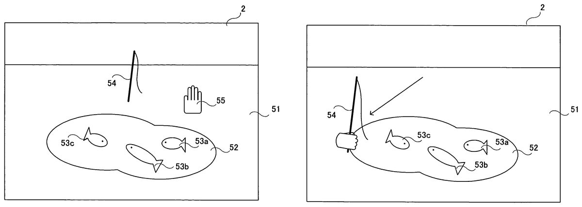
An exemplary video game to be played on a video game system as described above will now be described. The present embodiment is directed to a video game (fishing video game) in which an object (fishing rod) is moved in a virtual three-dimensional game space.FIG. 11shows an exemplary game screen of the present embodiment. InFIG. 11, displayed on the screen of the monitor2is a terrain including a ground51and a pond52. There are fish53ato53cin the pond52. A fishing rod54is displayed above the pond52. The ground51, the pond52, the fish53ato53cand the fishing rod54are objects present in a three-dimensional game space. Also displayed on the screen is a cursor55, being an example of a pointer image representing the position being pointed at by the controller7. In the present video game, the player uses the controller7to move the fishing rod54, being an example of the controlled object, in order to catch the fish53ato53cwith the fishing rod54. Note that the fishing rod54is an example of the controlled object and is also an example of the reference image. It is understood that different images may be used for the controlled object and the reference image. Even if the same three-dimensional object is used for the fishing rod54, different texture colors may be used on the object between when it is used as the controlled object and when it is used as the reference image.
FIG. 11shows the game screen immediately after the start of the game. Immediately after the start of the game, the fishing rod54is displayed at a predetermined position, e.g., near the center of the screen. Note however that, immediately after the start of the game, the player cannot control the fishing rod54. Immediately after the start of the game, the player needs to control the cursor55. The player can move the cursor55by changing the position pointed at by the controller7. Since the cursor55is displayed at the position pointed at by the controller7, the player can check the pointed position by looking at the cursor55. Immediately after the start of the game, the player moves the cursor55until the area of the cursor55includes at least a portion of the fishing rod54(e.g., so that the cursor55overlaps the fishing rod54).FIG. 12shows a game screen where the cursor55overlaps the fishing rod54. After moving the cursor55to a position shown inFIG. 12, the player can control the fishing rod54.
FIG. 13shows a game screen where the player is allowed to control the fishing rod54. After the cursor55overlaps the fishing rod54, the cursor55is erased from the screen as shown inFIG. 13. It is not always necessary to erase the cursor55, but the cursor55may be replaced with another cursor. Then, in order to indicate that the player is allowed to control the fishing rod54, the image of the fishing rod54is switched to another one in which the fishing rod54is shown to be being held by a hand. Then, the player can move the fishing rod54in the three-dimensional game space.FIG. 14shows a game screen after the fishing rod54is moved. The player, using the controller7, can freely move the fishing rod54across the three-dimensional space. The player can move the fishing rod not only in the up/down and left/right directions of the screen, but also in the depth direction of the screen.
FIG. 15shows the three-dimensional game space. As shown inFIG. 15, in the present embodiment, various three-dimensional objects, e.g., a terrain50including the ground51and the pond52, the fishing rod54, fish (not shown), etc., are placed in the world coordinate system being the game space. The terrain50is placed so that the X′Z′ plane of the game space is parallel to the ground51, and the Y′ axis is perpendicular to the ground51. The virtual camera for taking an image of the game space is positioned above the ground51. The viewing direction of the virtual camera is set with an angle of depression so that the virtual camera will look down the ground51(see an arrow56shown inFIG. 15). InFIG. 15, the viewing direction56of the virtual camera is facing the rear side.
After the player is allowed to control the fishing rod54as described above with reference toFIGS. 13 and 14, if the player moves the controller7in the left/right direction with respect to the markers8aand8b(parallel to the direction in which the markers8aand8bare arranged with respect to each other in the present embodiment), the fishing rod54moves in the X′-axis direction. If the player moves the controller7in the up/down direction with respect to the markers8aand8b(the up/down direction perpendicular to the direction in which the markers8aand8bare arranged with respect to each other), the fishing rod54moves in the Y′-axis direction. If the player moves the controller7in the forward/backward direction with respect to the markers8aand8b(the forward/backward direction perpendicular to the direction in which (the markers8aand8bare arranged with respect to each other), the fishing rod54moves in the Z′-axis direction. If the controller7is moved excessively in the left/right direction or in the up/down direction, the markers8aand8bwill be outside the range of the image sensing device40of the controller7. As a result, it is no longer possible to calculate the movement of the controller7, and the player is no longer able to control the fishing rod54.
The three-dimensional game space can be rendered as a two-dimensional game image by perspectively projecting the various objects in the view volume onto a two-dimensional screen plane, which is perpendicular to the viewing direction56of the virtual camera. The screen plane is not parallel to the horizontal plane of the game space. Usually, perspective projection is employed for stereoscopic effect, whereby the two-dimensional image is given perspective distortion. Thus, the position of the fishing rod54, which moves across the three-dimensional space, as displayed on the screen does not always coincide with the position pointed at by the controller7. When the controller7is moved in the forward/backward direction, for example, the pointed position does not change, but the fishing rod54moves in the Z′-axis direction, thereby changing its display position, so that the position pointed at by the controller7no longer coincides with the display position of the fishing rod54.
If the player needs to start controlling the fishing rod54immediately after the start of the game (when the cursor55is not yet displayed on the screen), the player will have to control the fishing rod54without knowing where the pointed position is. Therefore, it is likely that the player will move the controller7beyond the controllable range, whereby a situation frequently occurs where the fishing rod54cannot be controlled. In view of this, in the present embodiment, the player is allowed to check the pointed position using the cursor55before the player starts controlling the fishing rod54. As the player is allowed to move the cursor55according to the pointed position so as to align the cursor55with the fishing rod54, the player can check the pointed position before the player starts controlling the fishing rod54. While the player moves the cursor55, the player is also allowed to check to what extent the player can move the controller7without going outside the controllable range. As the player is allowed to check the pointed position before the player starts controlling the fishing rod54, the player can have some idea of the location of the pointed position while the player is controlling the fishing rod54. Thus, it is unlikely that the player moves the controller7beyond the controllable range, thereby preventing the fishing rod54from frequently becoming uncontrollable. Moreover, since the player can have some idea of the location of the pointed position while the player is controlling the fishing rod54, the controllability of the controller7is improved.
In the present embodiment, if the controller7goes outside the controllable range, the game screen returns to the initial screen immediately after the start of the game (as shown inFIG. 11). Specifically, the fishing rod54returns to its initial position, and can no longer be controlled by the player. Moreover, the cursor55is displayed again on the screen. Thus, if the controller7goes outside the controllable range, the player needs to again move the cursor55to align the cursor55with the fishing rod54. Therefore, when the controller7goes outside the controllable range, the player is allowed to again check the pointed position.
In other embodiments, the player may be allowed to check the pointed position using the cursor55only immediately after the start of the game, or only after the controller7goes outside the controllable range.
The details of the game process performed by the video game device3will now be described. First, important data to be used in the game process will be described with reference toFIG. 16.FIG. 16shows important data to be stored in the main memory13of the video game device3. Referring toFIG. 16, the main memory13stores control data61, reference data62, pointed position calculation data63, depth calculation data64, operation result data65, cursor data66, object data67, control flag data68, etc. In addition to those shown inFIG. 16, the main memory13also stores other data necessary for the game process, such as character data (e.g., the image data and the position data of the fish53ato53c), and game space data (e.g., the terrain data including the ground51, the pond52, etc.).
The control data61is data representing an operation made on the controller7, and is obtained from the controller7. The control data61includes marker position data611. The marker position data611represents the positions of the markers included in the captured image (marker positions). If two marker images are included in the captured image, two sets of coordinates representing the positions of the two marker images are stored as the marker position data611. If only one marker image is included in the captured image, one set of coordinates representing the position of the marker image is stored as the marker position data611. The control data61is obtained from the controller7at regular intervals, as described above, and the control data stored in the main memory13is updated with the newly obtained control data61. Moreover, the control data61includes data representing the status of the control section32(i.e., data indicating whether or not each control switch of the control section32is being pressed) and data representing the detection results from the acceleration sensor37.
The reference data62is data regarding the captured image when the controller7is in a reference state. The reference state of the controller7is determined by the player in the calibration process to be described later. The reference data62includes reference direction vector data621, reference middle point position data622and minimum distance data623. The reference direction vector data621represents a vector (reference direction vector) extending between two marker positions as obtained when the controller7is in the reference state. The reference middle point position data622represents the position of the middle point (reference middle point position) between two marker positions as obtained when the controller7is in the reference state. The minimum distance data623represents the minimum distance between an edge of the captured image and any of the two marker positions as obtained when the controller7is in the reference state (seeFIG. 19to be described later). The minimum distance data623represents two different minimum distances, including the minimum distance with respect to the x-axis direction in the xy coordinate system of the captured image, and the minimum distance with respect to the y-axis direction.
The pointed position calculation data63is data used for calculating the position pointed at by the controller7. The pointed position calculation data63includes first middle point position data631, direction vector data632, rotation angle data633, second middle point position data634and movement vector data635. The first middle point position data631represents the position of the middle point (first middle point position) between two marker positions represented by the marker position data611. The direction vector data632represents a vector (direction vector) extending between two marker positions represented by the marker position data611. The rotation angle data633represents the angle between the current direction vector and the reference direction vector. The second middle point position data634represents a position (second middle point position) obtained by rotating the position of the first middle point position by the angle represented by the rotation angle data633about the center of the captured image. The movement vector data635is a vector (movement vector) representing the difference between the current second middle point position and the reference middle point position. The movement vector is a vector representing how far the current pointed position is with respect to the pointed position in the reference state.
The depth calculation data64is data used for calculating a depth value to be described later. The depth value is an indication of the position of the controller7in the forward/backward direction, and is a value corresponding to the distance from the controller7to the markers8aand8b. The depth calculation data64includes marker image interval data641and actual distance data642. The marker image interval data641represents the distance (marker image interval) between two marker positions represented by the marker position data611. The actual distance data642represents the distance (actual distance) from the controller7to the markers8aand8b.
The operation result data65represents the results of an operation on the controller7, which are obtained from the pointed position calculation data63and the depth calculation data64. The operation result data65includes pointed position data651and depth value data652. The pointed position data651represents the pointed position on the screen. The video game device3calculates the pointed position data651by using the pointed position calculation data63. The depth value data652is calculated by using the depth calculation data64, and represents the depth value.
The cursor data66is data regarding the cursor displayed on the screen (the cursor55shown inFIG. 11, etc.). The cursor data66includes cursor screen position data661. The cursor screen position data661represents the position of the cursor on the screen.
The object data67is data regarding the object controlled by the player (the fishing rod54). The object data67includes object screen position data671and object space position data672. The object screen position data671is two-dimensional coordinates representing the position of the fishing rod on the screen. The object space position data672is three-dimensional coordinates representing the position of the fishing rod in the game space.
The control flag data68is data representing the contents of the control flag. The control flag is a flag indicating whether or not the fishing rod is being controllable. Specifically, the control flag is ON when the fishing rod is controllable, and is OFF otherwise.
Referring now toFIGS. 17 to 32, the details of the game process performed by the video game device3will be described.FIG. 17is a flow chart showing the game process performed by the video game device3. When the power of the video game device3is turned ON, the CPU10of the video game device3executes a boot program stored in a boot ROM (not shown), thus initializing various units such as the main memory13. The video game program stored in the optical disk4is loaded to the main memory13, and the CPU10starts executing the video game program. The flowchart ofFIG. 17shows the game process performed after the completion of the process described above. In the flow charts ofFIGS. 17 to 32, parts of the game process related to the operation of moving the cursor or the fishing rod by using the controller7are shown in detail, and other parts of the game process that are not directly related to the present invention will not be shown in detail.
First, in step S1, a three-dimensional game space is created and displayed on the monitor2. The CPU10creates a game space including the ground51, the pond52, etc. Moreover, the fish53ato53care placed in the pond52, and the fishing rod is placed at its predetermined initial position. The fishing rod is preferably placed so that the fishing rod is displayed near the center of the screen. A game image is produced from the created game space as viewed from the virtual camera in the viewing direction, and the produced game image is displayed on the monitor2.
Then, in step S2, the calibration process is performed. The calibration process is a process of allowing the player to set the reference state of the controller7. Through this process, the reference state of the controller7is determined, and the reference data62is stored in the main memory13. Referring now toFIGS. 18 to 20, the calibration process will be described.
FIG. 18is a flow chart showing the details of step S2shown inFIG. 17. First, in step S31of the calibration process of step S2, the control data61is obtained from the controller7. As described above, the control data61includes the marker position data611. Then, in step S32, it is determined whether or not a marker is detected. Specifically, the CPU10determines whether or not the marker position data611included in the control data61obtained in step S31represents one or two sets of coordinates. If the controller7is outside the controllable range and no marker is being detected, the marker position data611will contain no set of coordinates, indicating that no marker position is being detected. If the controller7is within the controllable range and one or more markers are being detected, the marker position data611will contain one or two sets of coordinates. If it is determined in step S32that a marker is detected, the process proceeds to step S33. If not, the process of step S32is repeated. Thus, the CPU10repeats step S32until a marker is detected.
In step S33, the CPU10displays an image on the screen to prompt the player for a trigger input. A trigger input is made to determine the reference state of the controller7, and is made by pressing the A button32iof the controller7in the illustrated example. Specifically, in step S33, a prompt such as “Aim the controller at the center of the screen, and press A button” is displayed on the screen. In response to this prompt, the player presses the A button while aiming the controller7at the center of the screen. The position and direction of the controller7at the time when the player presses the A button are stored as the reference state.
Then, in step S34, it is determined whether or not a trigger input is detected. Specifically, the CPU10obtains the control data61from the controller7, and determines whether or not there has been a trigger input on the A button32i. If it is determined in step S34that there is a trigger input, the process proceeds to step S35. If not, step S34is repeated. Thus, the CPU10repeats step S34until a trigger input is detected.
In step S35, the CPU10obtains the marker positions at the time of the trigger input. Specifically, the CPU10obtains the marker position data611, which is contained in the control data61indicating that there has been a trigger input on the A button32i.FIG. 19shows a two-dimensional coordinate system of the marker positions obtained at the time of the trigger input. As shown inFIG. 19, each marker position is represented by a set of integer coordinates in the xy coordinate system ranging from (0, 0) to (1024, 768). InFIG. 19, two marker positions Mi1and Mi2are included in the captured image.
Then, in step S36, the CPU10calculates the reference direction vector based on the marker positions obtained in step S35. Specifically, the CPU10obtains, as the reference direction vector, a vector Vi extending between the marker positions Mi1and Mi2, which are obtained in step S35(seeFIG. 19). Which one of the two marker positions Mi1and Mi2is the start or end point of the vector is determined based on a predetermined condition. The predetermined condition is not limited to any particular condition. For example, one of the two marker positions with a smaller x coordinate may be the start point with the other being the end point of the vector. The reference direction vector obtained in step S36is stored in the main memory13as the reference direction vector data621. The reference direction vector data621may be a two-dimensional vector specifying the start point and the end point of the reference direction vector, or may alternatively be a value representing the direction of the reference direction vector.
Then, in step S37, the CPU10calculates the minimum distance from a marker position to an edge of the captured image. Specifically, the CPU10calculates the distance from each marker position to an edge of the captured image for each of the x-axis direction and the y-axis direction. Then, the shortest distance for the x-axis direction and the shortest distance for the y-axis direction are selected as being minimum distances. Referring toFIG. 19, the CPU10calculates, for the x-axis direction, the distance from the marker position Mi1to the right edge of the captured image (x=1024), the distance from the marker position Mi1to the left edge of the captured image (x=0), the distance from the marker position Mi2to the right edge of the captured image (x=1024), and the distance from the marker position Mi2to the left edge of the captured image (x=0). Then, the shortest distance of all the distances calculated (the distance from the marker position Mi2to the right edge of the captured image in the illustrated example) is determined to be the minimum distance Lx for the x-axis direction. Similarly, the minimum distance Ly for the y-axis direction is obtained. The minimum distance for the x-axis direction and that for the y-axis direction are stored in the main memory13as the minimum distance data623.
Then, in step S38, the reference middle point position is calculated based on the marker positions obtained in step S35. Specifically, the CPU10obtains, as a reference middle point position Ci, the position of the middle point between the marker positions Mi1and Mi2obtained in step S35(seeFIG. 19). The reference middle point position obtained in step S38is stored in the main memory13as the reference middle point position data622.
Then, instep S39, the CPU10performs a coordinate system conversion. The coordinate system shown inFIG. 19, where a position can take integer coordinates ranging from (0, 0) to (1024, 768), is referred to as the detection coordinate system. In step S39, the CPU10converts the detection coordinate system to the calculation coordinate system.FIG. 20shows a two-dimensional area on the captured image as represented in the calculation coordinate system. As shown inFIG. 20, the calculation coordinate system is a coordinate system (an x′y′ coordinate system) where the center of the captured image is the origin with each coordinate ranging from −1 to 1 from edge to edge. The x′ axis of the calculation coordinate system is in the same direction as the x axis of the detection coordinate system, and the y′ axis of the calculation coordinate system is in the same direction as the y axis of the detection coordinate system. The CPU10converts the minimum distance calculated in step S37and the value of the reference middle point position calculated in step S38in the detection coordinate system to those in the calculation coordinate system. Then, the reference middle point position data622and the minimum distance data623stored in the main memory13are updated with the converted values. Note that step S39is merely a conversion of coordinate system, and does not change the reference middle point position in the captured image. While the scale of the detection coordinate system varies depending on the resolution of the image capturing means, the calculation coordinate system is irrespective of the resolution of the image capturing means. Thus, by converting the detection coordinate system to the calculation coordinate system in step S39, the operation with the reference middle point position and the minimum distances can be performed independent of the resolution of the image capturing means. After step S39, the CPU10exits the calibration process. The calibration process may be omitted if the reference data62can be provided in advance. Alternatively, the interval between the markers8aand8bor the distance between the markers and the controller may be inputted.
Referring back toFIG. 17, the process proceeds to steps S3to S20after step S2. In steps S3to S20, the player can control the cursor or the fishing rod. The loop through steps S3to S20is iterated once per frame.
First, in step S3, the control data61is obtained from the controller7. As described above, the control data61includes the marker position data611. Then, in step S4, it is determined whether or not a marker is detected. The determination process of step S4is similar to that of step S32described above. If it is determined in step S4that a marker is detected, the process proceeds to step S5. If not, the process proceeds to step S16. Failing to detect a marker here means that the controller7is being outside the controllable range.
In step S5, the CPU10performs a middle point position calculation process. Referring now toFIGS. 21 to 27, the details of the middle point position calculation process will be described.FIG. 21is a flow chart showing the details of step S5shown inFIG. 17.FIG. 22shows the coordinate system (the detection coordinate system) of the marker positions obtained in step S3. The process of step S5will now be described, assuming that marker positions M1and M2as shown inFIG. 22are obtained in step S3.
First, in step S41of the middle point position calculation process of step S5, the CPU10calculates the direction vector based on the marker positions obtained in step S3. Specifically, the CPU10obtains, as the direction vector, a vector V1extending between the marker positions M1and M2obtained in step S3(seeFIG. 22). Which one of the two marker positions M1and M2is the start or end point of the vector is determined based on a predetermined condition. The condition is the same as that used in step S36. The direction vector obtained in step S41is stored in the main memory13as the direction vector data632. The direction vector data632may be a two-dimensional vector specifying the start point and the end point of the direction vector, or may alternatively be a value representing the direction of the direction vector.
Then, in step S42, the CPU10calculates the first middle point position based on the marker positions obtained in step S3. Specifically, the CPU10obtains, as a first middle point position C1, the position of the middle point between the marker positions M1and M2obtained in step S3(seeFIG. 22). The first middle point position obtained in step S42is stored in the main memory13as the first middle point position data631. Then, in step S43, the CPU10converts the first middle point position in the detection coordinate system to that in the calculation coordinate system. Then, the first middle point position data631stored in the main memory13are updated with the converted values.
Then, in step S44, based on the direction vector obtained in step S41and the reference direction vector obtained in step S2, the CPU10calculates the angle (rotation angle) θ between the reference direction vector and the direction vector. Specifically, the CPU10calculates the rotation angle θ by referring to the reference direction vector data621and the direction vector data632stored in the main memory13. The obtained rotation angle θ is stored in the main memory13as the rotation angle data633. The rotation angle θ is an indication of how much the controller7is turned from the reference state about an axis in the forward/backward direction. Therefore, by detecting the rotation angle θ, it is possible to detect the degree of rotation of the controller7about an axis in the forward/backward direction.
Then, in step S45, the CPU10calculates the second middle point position based on the first middle point position obtained in step S43and the rotation angle obtained in step S44.FIG. 23illustrates the process of step S45shown inFIG. 21. As shown inFIG. 23, a second middle point position C2is calculated as being a position obtained by rotating the first middle point position C1by the rotation angle E about the center of the captured image (the origin of the calculation coordinate system). The obtained second middle point position is stored in the main memory13as the second middle point position data634.
Therefore, even if the position pointed at by the controller7stays at the same point, the marker positions may vary depending on the rotation of the controller7about an axis in the forward/backward direction. Thus, it is not possible to calculate an accurate pointed position based on the first middle point position, which is simply calculated from the marker positions. In the present embodiment, through steps S44and S45, the CPU10calculates the second middle point position by correcting the first middle point position while taking into account the rotation of the controller7about an axis in the forward/backward direction. Specifically, the CPU10calculates the degree of rotation of the controller7with respect to the reference state in step S44, and rotates the first middle point position depending on the degree of rotation in step S45, thereby correcting the shift in the middle point position occurring due to the rotation of the controller7.
In step S46, following step S45, the CPU10calculates a vector (difference vector) representing the difference between the reference middle point position and the second middle point position.FIG. 24illustrates the process of step S46shown inFIG. 21. As shown inFIG. 24, a difference vector V2is a vector extending from the reference middle point position Ci to the second middle point position C2. The CPU10calculates the difference vector by referring to the reference middle point position data622and the second middle point position data634stored in the main memory13.
Then, in step S47, the CPU10performs a scaling operation on the difference vector calculated in step S46. Specifically, the CPU10divides the x′-axis component of the difference vector by the minimum distance Lx for the x′-axis direction, and the y′-axis component of the difference vector by the minimum distance Ly for the y′-axis direction.FIG. 25illustrates the process of step S47shown inFIG. 21.FIG. 25shows a variation in the x′y′ coordinate system with the magnitude of the difference vector before the scaling operation and that after the scaling operation being equal to each other. Through the scaling operation, the magnitude of the difference vector is varied so that the area within a dotted-line boundary inFIG. 25is where −1≦x′≦1 and −1≦y′≦1 hold true. Thus, a scaling operation on the difference vector shown inFIG. 24yields a vector V2′ shown inFIG. 26. The CPU10takes the vector V2′ obtained by the scaling operation as the movement vector, and stores the vector V2′ in the main memory13as the movement vector data635. After step S47, the CPU10exits the middle point position calculation process.
FIG. 27shows the relationship between the controllable range and the difference vector. InFIG. 27, a dotted-line area A1represents the range of the pointed position where the controller7is within the controllable range. Moreover, a position P1is the pointed position in the reference state. A one-dot-chain-line area A2represents the range of the pointed position where the movement vector obtained by the scaling operation satisfies −1≦x′≦1 and −1≦y′≦1. It can be seen fromFIG. 27that in the range where the movement vector satisfies −1≦x′≦1 and −1≦y′≦1, the controller7is within the controllable range and the controllable range can be used effectively. Therefore, the controllable range can be used effectively by using the movement vector for controlling an object in the range where −1≦x′≦1 and −1≦y′≦1. In a case where the object moving range is limited, the movement vector and the object moving range can easily be associated with each other by associating the moving range with the range where the movement vector satisfies −1≦x′≦1 and −1≦y′≦1.
Referring back toFIG. 17, in step S6, following step S5, a depth value calculation process is performed. Referring now toFIGS. 28,29A and29B, the details of the depth value calculation process will be described.FIG. 28is a flow chart showing the details of step S6shown inFIG. 17.FIGS. 29A and 29Billustrate the process of step S6shown inFIG. 17.
First, in step S51of the depth value calculation process of step S6, the CPU10calculates a marker image interval mi (seeFIG. 29A) based on the marker positions obtained in step S3. Specifically, the CPU10calculates the distance mi between the two marker positions M1and M2obtained in step S3. The obtained distance is stored in the main memory13as the marker image interval data641.
Then, in step S52, the CPU10calculates the width w (seeFIG. 29B) across which the image sensing device40can take an image, with respect to the positions where the markers8aand8bare installed. Specifically, the CPU10calculates the width w as follows.
w=wi×m/mi
In the expression, m is the interval between the markers8aand8b(e.g., 30 cm), and is a fixed value. Moreover, wi is the width of the captured image of the image sensing device40for the width w, and is also a fixed value. Since the interval m and the width wi are both fixed values, they are stored in advance in the storage means of the video game device3. The interval m may be any suitable value depending on the environment in which the markers8aand8bare installed by the player. The interval between the installed markers8aand8bmay be inputted by the player as the interval m.
Then, in step S53, the CPU10calculates the distance d between the markers8aand8band the image sensing device40(the controller7) based on the width w and the viewing angle θ2of the image sensing device40. Specifically, the CPU10calculates the distance d as follows.
tan(θ2/2)=(w/2)/d=w/2d
Since the viewing angle θ2is a fixed value, it is stored in advance in the storage means of the video game device3. The obtained distance d is stored in the main memory13as the actual distance data642.
Then, in step S54, the CPU10calculates the depth value corresponding to the distance d. The depth value is calculated to be larger as the distance d is larger. There may be an upper limit and a lower limit for the depth value. The obtained depth value is stored in the main memory13as the depth value data652. After step S54, the CPU10exits the depth value calculation process.
Referring back toFIG. 17, in step S7, following step S6, it is determined whether or not the control flag is ON. The determination process of step S7is for determining whether or not the controlled object (fishing rod) is being controllable. Specifically, the CPU10refers to the control flag data68stored in the main memory13to determine whether or not the control flag is ON. If it is determined that the control flag is ON, i.e., if the object is being controllable, the process proceeds to steps S14and S15. If the control flag is OFF, i.e., if the object is not being controllable, the process proceeds to steps S8to S13. Specifically, step S8is performed while the player is controlling the cursor displayed on the screen (FIG. 11), and step S14is performed after the player has aligned the cursor with the object (FIGS. 13 and 14).
First, steps S8to S13will be described. In steps S8to S13, the player moves the cursor on the screen by using the controller7. In step S8, the pointed position calculation process is performed. Referring now toFIGS. 30,31A and31B, the details of the pointed position calculation process will be described.FIG. 30is a flow chart showing the details of step S8shown inFIG. 17.FIGS. 31A and 31Billustrate the process of step S8shown inFIG. 17. Note that it is assumed herein that the coordinate system for representing a position on the screen is an XY coordinate system, as shown inFIG. 31A. The XY coordinate system is a coordinate system where the upper left corner of the screen is the origin, the rightward direction of the screen is the positive X-axis direction, and the downward direction of the screen is the positive Y-axis direction. In the XY coordinate system, a position can take integer coordinates ranging from (0, 0) to (640, 480).
First, referring toFIGS. 31A and 31B, the pointed position calculation process will be outlined.FIG. 31Ashows an example of the movement vector V2′ obtained in step S5. If a movement vector as shown inFIG. 31Ais obtained, the pointed position (Xf,Yf) is calculated to be the position as shown inFIG. 31B. A vector V2″ shown inFIG. 31Bis obtained by V2″=−V2″×320. Thus, the pointed position is obtained by moving from the center of the screen (320, 240) by the vector V2″.
First, in step S56of the pointed position calculation process, the CPU10calculates the X coordinate on the screen based on the x′ coordinate of the movement vector obtained in step S5. Specifically, the CPU10refers to the movement vector represented by the movement vector data635stored in the main memory13, and calculates the X coordinate Xf of the pointed position as follows.
Xf=−xf×320+320
In this expression, xf is the x′ coordinate of the movement vector. The x′ coordinate of the movement vector may take a value smaller than −1 or a value larger than 1 depending on the reference state of the controller7determined in step S2. If the x′ coordinate is smaller than −1, the CPU10calculates the above expression with the x′ coordinate being −1. If the x′ coordinate is larger than 1, the CPU10calculates the above expression with the x′ coordinate being 1.
Then, in step S57, the CPU10calculates the Y coordinate on the screen based on the y′ coordinate of the movement vector obtained in step S5. Specifically, the CPU10refers to the movement vector represented by the movement vector data635stored in the main memory13, and calculates the Y coordinate Yf of the pointed position as follows.
Yf=−yf×240+240
In this expression, yf is they′ coordinate of the movement vector. The calculation is similar to that in step S56. If the y′ coordinate is smaller than −1, the CPU10calculates the above expression with the y′ coordinate being −1. If the y′ coordinate is larger than 1, the CPU10calculates the above expression with the y′ coordinate being 1.
The pointed position (Xf, Yf) is calculated through steps S56and S57as described above. The obtained the pointed position is stored in the main memory13as the pointed position data651. After steps S56and S57, the CPU10exits the pointed position calculation process.
Referring back toFIG. 17, in step S9, following step S8, a game space image is produced where the fishing rod is placed in its predetermined initial position. The CPU10produces the game space image as viewed from the virtual camera. Then, in step S10, the CPU10calculates the display position of the fishing rod on the screen. The display position of the fishing rod is obtained by calculating the position in the three-dimensional game space as being projected onto a projection plane, and then converting the position on the projection plane to a corresponding position on the screen. The position of the fishing rod on the screen is stored in the main memory13as the object screen position data671. In the present embodiment, the position of the fishing rod on the screen is constant at the time of step S10. Therefore, coordinates of the constant position may be stored in advance, and step S10may be skipped.
Then, in step S11, the CPU10places the cursor at the pointed position as obtained in step S9. Specifically, the CPU10updates the cursor screen position data661stored in the main memory13with the pointed position data651. Then, the CPU10produces a game image by laying a cursor image at the pointed position over the game image as produced in step S9. The produced game image is displayed on the screen in the display process to be described later.
Then, in step S12, it is determined whether or not the position of the cursor coincides with the position of the fishing rod on the screen. Specifically, the CPU10refers to the cursor screen position data661and the object screen position data671stored in the main memory13, and determines whether or not the position of the cursor on the screen is within a predetermined distance from the position of the fishing rod on the screen. If so, it is determined that the position of the cursor coincides with the position of the fishing rod on the screen. If it is determined in step S12that the cursor position coincides with the position of the fishing rod on the screen, the process proceeds to step S13. If it is determined that the cursor position does not coincide with the position of the fishing rod on the screen, the process proceeds to step S19, skipping step S13.
Instep S13, the control flag is turned ON. Specifically, the CPU10sets the control flag data68stored in the main memory13so that it indicates ON. Then, after step S13and until the controlled object flag is turned OFF, the player can control the controlled object by using the controller7. After step S13, the process proceeds to step S19to be described later.
Steps S14and S15will now be described. In steps S14and S15, the player uses the controller7to move the object (fishing rod) in the game space. In step S14, the CPU10performs an object position calculation process.
FIG. 32is a flow chart showing the details of step S14shown inFIG. 17. First, in step S61of the object position calculation process, the CPU10calculates the X′ coordinate of the X′Y′Z′ coordinate system (seeFIG. 15) of the game space based on the x′ coordinate of the movement vector obtained in step S5. Specifically, the CPU10refers to the movement vector represented by the movement vector data635stored in the main memory13, and calculates the X′ coordinate Ox of the object position as follows.
Ox=xf×α+a
In this expression, xf is the x′ coordinate of the movement vector, and α and a are each a predetermined constant. As in steps S56and S57, the CPU10may calculate the above expression while limiting the x′ coordinate within the range of −1≦xf≦1. Specifically, the CPU10may calculate the above expression with the x′ coordinate being −1 when it is smaller than −1 and with the x′ coordinate being 1 when it is larger than 1.
Then, in step S62, the CPU10calculates the Y′ coordinate of the X′Y′Z′ coordinate system (seeFIG. 15) the game space based on the y′ coordinate of the movement vector obtained in step S5. Specifically, the CPU10refers to the movement vector represented by the movement vector data635stored in the main memory13, and calculates the Y′ coordinate Oy of the object position as follows.
Oy=yf×β+b
In this expression, yf is the y′ coordinate of the movement vector, and β and b are each a predetermined constant. As in step S61, the CPU10may calculate the above expression while limiting the y′ coordinate within the range of −1≦yf≦1.
Then, in step S63, the CPU10calculates the Z′ coordinate of the X′Y′Z′ coordinate system (seeFIG. 15) of the game space based on the depth value obtained in step S6. Specifically, the CPU10refers to the depth value data652stored in the main memory13, and calculates the Z′ coordinate Oz of the object position as follows.
Oz=zf×γ+c
In this expression, zf is the depth value, and γ and c are each a predetermined constant. The position of the fishing rod in the game space is calculated through steps S61to S63as described above. The obtained coordinates in the X′Y′Z′ coordinate system are stored in the main memory13as the object space position data672.
After step S63, in steps S64to S66, a process for allowing the player to pull up the fishing rod is performed. This action is performed in order to take in a fish being hooked. The player can take in the fish by doing this action while the fish is hooked. In the present embodiment, this action is activated when the position pointed at by the controller7moves in the up/down direction of the screen at a predetermined speed or higher.
In step S64, the CPU10calculates the amount by which the y′ coordinate of the movement vector has changed from the previous value. Specifically, the CPU10calculates the difference between the y′ coordinate of the movement vector in the previous frame and that in the current frame. Then, in step S65, it is determined whether or not the amount of change is greater than or equal to a predetermined value. If so, the process proceeds to step S66. In step S66, the action of pulling up the fishing rod is rendered. A few-frame-long animation of this action is rendered on the screen in the display process to be described later. If the amount of change is smaller than the predetermined value, the CPU10exits the object position calculation process, skipping step S66.
Referring back toFIG. 17, in step S15, following step S14, a game space image is produced where the fishing rod is placed at the position calculated in step S14. The CPU10produces the game space image as viewed from the virtual camera. Then, in the display process of step S19to be described later, the fishing rod will be displayed on the screen as being moved to the position specified by the player using the controller7. Since the cursor is not displayed in steps S14and S15, the cursor will not appear during frames in which steps S14and S15are performed. After step S15, the process proceeds to step S19to be described later.
Steps S16to S18will now be described. Steps S16to S18are performed if the controller7goes outside the controllable range while controlling the cursor or the fishing rod, i.e., if the determination result is negative in step S4. First, in step S16, the control flag is turned OFF. Specifically, the CPU10sets the control flag data68stored in the main memory13so that it indicates OFF. Then, after step S16and until the controlled object flag is turned ON, the player cannot control the controlled object by using the controller7.
Then, in step S17, the fishing rod is placed in its initial position in the game space. Specifically, the CPU10updates the object space position data672stored in the main memory13with the predetermined initial position. Thus, when the controller7goes outside the controllable range, the fishing rod returns to its initial position. Then, in step S18, a game space image is produced where the fishing rod is placed at the position calculated in step S17. After step S18, the process proceeds to step S19.
In step S20, the game image produced in step S11, S15or S19is displayed on the screen of the monitor2. Then, in step S20, the CPU10determines whether or not the game is over. The determination of step S20is based on, for example, whether the player has completed the game (whether the player has taken all the fish) or whether a time limit has elapsed in a case where such a time limit is set in the game. If it is determined in step S20that the game is not over, the process returns to step S3to repeat the loop through steps S3to S20until it is determined that the game is over. If it is determined that the game is over, the CPU10exits the game process shown inFIG. 17.
If there is only one marker position represented by the marker position data obtained in step S3, the first middle point position cannot be calculated in step S5. In such a case, the other marker position is estimated based on the direction vector data632from the previous frame. Specifically, if the detected marker position is (1000, 500) and the direction vector from the previous frame is (100, 0), the other marker position can be estimated to be (1100, 500). Thus, the other, undetected marker position can be calculated with some accuracy. Therefore, even if only one marker is detected by the image capturing/processing section35, it is possible to calculate the first middle point position. However, the marker position estimation is not performed if only one marker position is detected in the current frame and if none was detected in the previous frame. This is because an accurate estimation cannot be done in such a case.
In the present embodiment, it is determined that the position of the marker object in the captured image (the second middle point position in the embodiment) can be calculated if the image capturing/processing section35of the controller7can detect at least one marker. In other embodiments, it may be determined that the position of the marker object can be calculated only if two markers are detected. Specifically, step S5may be performed only if it is determined in step S4that two marker positions are detected.
In the present embodiment, the fishing rod is returned to its initial position when the image capturing/processing section35of the controller7fails to detect the marker. In other embodiments, instead of returning the fishing rod to the initial position immediately after the marker detection first fails, the fishing rod may be returned to the initial position only if the marker detection continues to fail over a predetermined period of time. In the present fishing video game, the player may rapidly jerk the controller7to move the pointed position up and down in order to pull up the fishing rod, in which case the controller7may go outside the controllable range. If the fishing rod is returned to the initial position immediately after the controller7goes outside the controllable range, it will be difficult for the player to do the pull-up action, degrading the controllability for the player. The controllability can be improved if the position of the fishing rod is kept unchanged even when the controller7goes outside the controllable range for a short period of time for the pull-up action.
In the present embodiment, before the player controls the controlled object, the image of the fishing rod being the controlled object is displayed at or near the center of the screen. Then, the player is allowed to move the cursor to align the cursor with the image of the fishing rod so that the player can check the pointed position. In other embodiments, the player may align the cursor with any other suitable image, instead of the controlled object itself, as long as the player can check the pointed position. For example, a symbol image may be displayed at or near the center of the screen, and the player may align the cursor with the symbol image. Moreover, the display position of the symbol image is not limited to the center of the screen, but may be anywhere on the screen. The video game device may erase the symbol image when the cursor reaches a predetermined area including at least a part of the symbol image. Thus, after the player starts controlling the object (fishing rod), the symbol image, which is no longer needed, will not be displayed on the screen, which is preferable for the player.
Where the symbol image is displayed as a target with which the cursor is to be aligned, the fishing rod does not have to be displayed at or near the center of the screen before the player starts controlling the fishing rod. Then, even when the controller7goes outside the controllable range while the player is controlling the fishing rod, the fishing rod does not have to be returned to the center of the screen. For example, the video game device3can leave the fishing rod where it was immediately before the controller7went outside the controllable range. When the fishing rod is uncontrollable, the fishing rod may be visually altered to indicate to the player that the fishing rod is being uncontrollable (e.g., by altering the color or shape of the fishing rod).
In the present embodiment, the three (XYZ) components obtained according to the movement of the controller7are given directly to the coordinates of the object in the game space so as to move the object. Alternatively, the vector V2′ or the vector V2″ described above with reference toFIGS. 26,31A and31B may be used as a direction input of a so-called “analog stick”. In a conventional video game program using an analog stick, the tilt direction and the tilt amount of the analog stick are passed, as an analog stick input, to the video game program. Based on the current position and direction of the character in the game space and based on the received tilt direction and the tilt amount, the video game program determines the distance by which the character is moved and the direction in which it is moved. In the present embodiment, the vector V2″ shown inFIG. 31Bis used, instead of the tilt direction and the tilt amount of the analog stick. Thus, with respect to the current position of the character, the direction in which the character is moved and the amount by which it is moved are determined based on the vector V2″. Therefore, while the controller7is within the controllable range, the player can move the controller7left, right, up and down to move the character in the game space based on a vector calculated according to the movement of the controller7. In this case, however, since the movement of the controller7is used as an analog stick input, the pointed position based on the controller7may not coincide with the display position of the character. Thus, similar problems to those set forth above may occur. Never the less, the present invention can be applied to address the problems.
Specifically, the video game device3displays an alignment marker image, with which the cursor is to be aligned, at or near the center of the screen. Then, the cursor is displayed at the position pointed at by the controller7as described above. The alignment marker image may be an image of the player character itself, or may alternative be another image. When the player has aligned the cursor with the alignment marker image or moved the cursor nearby, the player is allowed to control the player character by using the controller7. Through this operation, the player will know the pointed position before the player starts controlling the player character.
The exemplary embodiment presented herein can be used in a video game system, etc., for improving the controllability of an object using an optical pointing device, or the like.
While the exemplary embodiment has been described in detail, the foregoing description is in all aspects illustrative and not restrictive. It is understood that numerous other modifications and variations can be devised without departing from the scope of the exemplary embodiment.
Claims
- A non-transitory computer-readable physical storage medium having tangibly recorded thereon a video game program to be executed by a computer of a video game device, wherein the video game program obtains control data from a control device including an image capturing unit that captures an image of a marker object, wherein the control data is captured image data obtained by the image capturing unit or data obtained by performing a predetermined operation on the captured image data, wherein the video game program displays a game image on a display device, the game image being an image of a virtual game space in which a controlled object is moved by a game process using the control data, and wherein the video game program instructs the computer to perform: displaying a reference image at a predetermined position on a screen of the display device;displaying a pointer image at a position on the screen pointed at by the control device;not controlling the controlled object when the pointer image has not reached inside a predetermined area including at least a portion of the reference image, and controlling the controlled object to act according to a position of the marker object in the captured image based on the control data after the pointer image reaches inside the predetermined area, wherein: the video game program instructs the computer to further perform detection determination for determining whether or not a position of at least one marker object is in the captured image;and the displaying a reference image and the displaying a pointer image are performed when it is determined that at least one marker position is not detected in the captured image.
- The non-transitory computer-readable physical storage medium according to claim 1 , wherein the video game program instructs the computer to further perform erasing the pointer image when the pointer image reaches inside a predetermined area defined based on a position of the reference image.
- The non-transitory computer-readable physical storage medium according to claim 1 , wherein it is determined in the detection determination that the marker position is not detected when a part or whole of an image of the marker object is not included in the captured image.
- The non-transitory computer-readable physical storage medium according to claim 1 , wherein: the controlled object is displayed as the reference image in the displaying a reference image;and in the controlling the controlled object, a position of the controlled object is controlled so that the controlled object is displayed at the predetermined position when it is determined that at least one marker position is not detected.
- The non-transitory computer-readable physical storage medium according to claim 1 , wherein in the displaying a pointer image, the position on the screen pointed at by the control device is calculated based on a position of the marker object in the captured image.
- The non-transitory computer-readable physical storage medium according to claim 1 , wherein the controlling the controlled object includes: position determination for determining whether or not the pointer image has reached within a predetermined area defined based on a position of the reference image by comparing a position of the pointer image on the screen with the position of the reference image on the screen;and control start for starting to control the controlled object when it is determined in the position determination that the pointer image has reached within the predetermined area defined based on the position of the reference image.
- The non-transitory computer-readable physical storage medium according to claim 1 , wherein: the controlled object is displayed as the reference image in the displaying a reference image;and the controlled object displayed in the displaying a reference image is controlled in the controlling the controlled object.
- The non-transitory computer-readable physical storage medium according to claim 1 , wherein the controlled object is controlled to be moved in a three-dimensional virtual game space in the controlling the controlled object.
- The non-transitory computer-readable physical storage medium according to claim 8 , wherein: the video game program instructs the computer to further perform calculating a distance between two predetermined points in an image of the marker object included in a captured image obtained by the image capturing unit;and in the controlling the controlled object, a movement of the controlled object in the three-dimensional virtual game space with respect to a depth direction of the screen is controlled based on the marker position and the distance.
- The non-transitory computer-readable physical storage medium according to claim 1 , wherein the control device is a handheld device.
- A video game system, comprising: a control device including an image capturing unit that captures an image of a marker object, a video game device for displaying a game image on a display device, the game image being an image of a virtual game space in which a controlled object is moved by a game process using control data, the control data being captured image data obtained by the image capturing unit or data obtained by performing a predetermined operation on the captured image data, the video game system further comprising: reference image display control programmed logic circuitry for displaying a reference image at a predetermined position on a screen of the display device;pointer image display programmed logic circuitry for displaying a pointer image at a position on the screen pointed at by the control device;image erasing programmed logic circuitry for erasing the pointer image when the pointer image reaches inside a predetermined area defined based on a position of the reference image;object control programmed logic circuitry for not controlling the controlled object when the pointer image has not reached inside a predetermined area including at least a portion of the reference image, and for controlling the controlled object to act according to a position of the marker object in the captured image based on the control data after the pointer image reaches inside the predetermined area;detection determination programmed logic circuitry for determining whether or not a position of at least one marker object is in the captured image;and the displaying a reference image and the displaying a pointer image are performed when it is determined that at least one marker position is not detected in the captured image.
- The video game system according to claim 11 , wherein the control device is a handheld device.
Disclaimer: Data collected from the USPTO and may be malformed, incomplete, and/or otherwise inaccurate.