U.S. Pat. No. 7,783,535
VIDEO GAME APPARATUS AND INFORMATION STORAGE MEDIUM FOR VIDEO GAME
AssigneeNintendo Co., Ltd.
Issue DateJanuary 15, 2004
Illustrative Figure
Abstract
A video game apparatus includes a CPU that detects a program control code included in a land object in the vicinity of a player object, and then, the CPU determines a kind of the land object. If the land object is “hole”, the CPU executes a “hole operation” subroutine. Similarly, if the land object is “wall”, “door” or “ladder”, the CPU performs “wall operation”, “door operation” or “ladder” subroutine.
Description
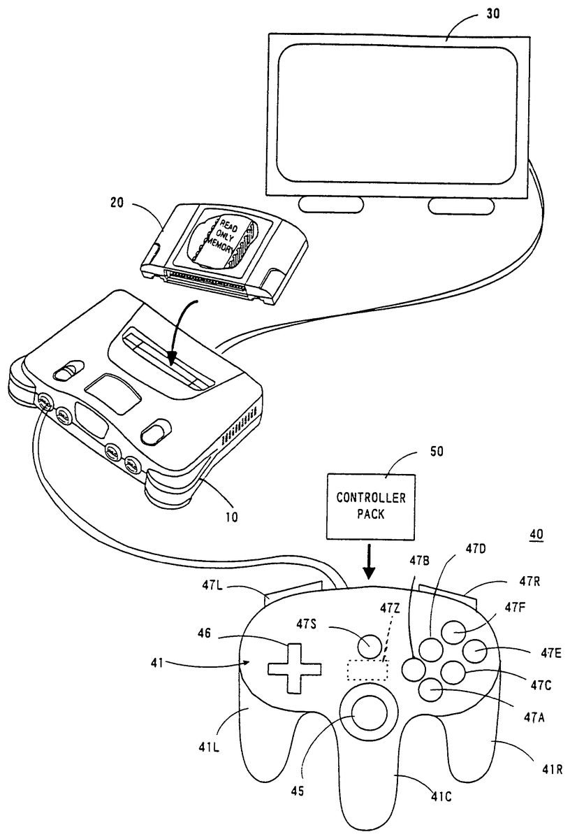
DETAILED DESCRIPTION OF THE PREFERRED EMBODIMENTS Referring toFIG. 1, a video game apparatus in this embodiment includes a video game machine10, a ROM cartridge20as one example of an information memory medium, a display unit30connected to the video game machine10, and a controller40. The controller40is dismountably mounted with a controller pack50. The controller40is structured by a plurality of switches or buttons provided on the housing41in a form graspable by both or one hand. Specifically, the controller40includes handles41L,41C,41R downwardly extending respectively from a left end, a right end and a center of the housing41, providing an operation area on a top surface of the housing41. In the operation area, there are provided an analog-inputtable joystick (hereinafter referred to as “analog joystick”)45at a central lower portion thereof, a cross-shaped digital direction switch (hereinafter called “cross switch”)46on the left side, and a plurality of button switches47A,47B,47D,47E and47F on the right side. The analog joystick45is used to input a moving direction and/or moving speed or moving amount of the player object (object to be operated by a player through a controller) as determined by an amount and direction of joystick inclination. The cross switch46is used to designate a moving direction of the player object, in place of the joystick45. The button switches47A and47B are used to designate a motion of the player object. Button switches47C-47D are used to switch over a visual point of a three-dimension image camera or adjust speed or the like of the player object. A start switch47S is provided almost at a center of the operation area. This start switch47S is operated when starting a game. A switch47Z is provided at a backside of the central handle41C. This switch47Z is utilized, for example, as a trigger switch in a shoot game. Switches47L and47R are provided at upper left and right of ...
DETAILED DESCRIPTION OF THE PREFERRED EMBODIMENTS
Referring toFIG. 1, a video game apparatus in this embodiment includes a video game machine10, a ROM cartridge20as one example of an information memory medium, a display unit30connected to the video game machine10, and a controller40. The controller40is dismountably mounted with a controller pack50.
The controller40is structured by a plurality of switches or buttons provided on the housing41in a form graspable by both or one hand. Specifically, the controller40includes handles41L,41C,41R downwardly extending respectively from a left end, a right end and a center of the housing41, providing an operation area on a top surface of the housing41. In the operation area, there are provided an analog-inputtable joystick (hereinafter referred to as “analog joystick”)45at a central lower portion thereof, a cross-shaped digital direction switch (hereinafter called “cross switch”)46on the left side, and a plurality of button switches47A,47B,47D,47E and47F on the right side.
The analog joystick45is used to input a moving direction and/or moving speed or moving amount of the player object (object to be operated by a player through a controller) as determined by an amount and direction of joystick inclination. The cross switch46is used to designate a moving direction of the player object, in place of the joystick45. The button switches47A and47B are used to designate a motion of the player object. Button switches47C-47D are used to switch over a visual point of a three-dimension image camera or adjust speed or the like of the player object.
A start switch47S is provided almost at a center of the operation area. This start switch47S is operated when starting a game. A switch47Z is provided at a backside of the central handle41C. This switch47Z is utilized, for example, as a trigger switch in a shoot game. Switches47L and47R are provided at upper left and right of a lateral surface of the housing41.
Incidentally, the above-stated button switches47C-47F can also be used to control the motion and/or moving speed (e.g. acceleration or deceleration) of the player object in a shoot or action game, besides for the purpose of switching the camera visual point. However, these switches47A-47F,47S,47Z,47L and47R can be arbitrarily defined in their function depending upon a game program.
FIG. 2is a block diagram of the video game system of theFIG. 1embodiment. The video game machine10incorporates therein a central processing unit (hereinafter referred to as “CPU”)11and a coprocessor (reality coprocessor: hereinafter referred to as “RCP”)12. The RCP12includes a bus control circuit121for controlling buses, a signal processor (reality signal processor; hereinafter referred to as “RSP”)122for performing polygon coordinate transformation, shading treatment and so on, and a rendering processor (reality display processor; hereinafter referred to as “RDP”)46for rasterizing polygon data into an image to be displayed and converting the same into a data form (dot data) memorable on a frame memory.
The RCP12is connected with a cartridge connector13for unloadably loading a ROM cartridge20having an external ROM21incorporated therein, a disc-drive connector197for detachably mounting a disc drive29, and a RAM14. Also, the RCP12is connected with DAC (Digital/Analog Converters)15and16for respectively outputting a sound signal and video signal to be processed by the CPU11. Further, the RCP12is connected with a controller control circuit17to serially transfer operating data on one or a plurality of controllers40and/or controller pack50.
The bus control circuit121included in the RCP12performs parallel/serial conversion on a command supplied in a parallel signal from the CPU via a bus, to thereby supply a serial signal to the controller control circuit18. Also, the bus control circuit121converts a serial signal inputted from the controller control circuit17into a parallel signal, giving an output to the CPU11via the bus. The data representative of an operating state (operating signal or operating data) read out of the controller40A-40D is processed by the CPU11, and temporarily stored within a RAM14, and so on. In other words, the RAM15includes a storage site for temporarily memorizing the data to be processed by the CPU11, so that it is utilized for smoothly reading and writing data through the bus control circuit121.
The sound DAC15is connected with a connector19aprovided at a rear face of the video game machine10. The video DAC16is connected with a connector19bprovided at the rear face of the video game machine10. The connector19ais connected with a speaker31of a display30, while the connector19bis connected with a display30such as a TV receiver or CRT.
The controller control circuit17is connected with a controller connector provided at the front face of the video game machine10. The connector18is disconnectably connected by a controller40through a connecting jack. The connection of the controller40to the connector18places the controller in electrical connection to the video game machine10, thereby enabling transmission/reception or transfer of data therebetween.
The controller control circuit17is used to transmit and receive data in serial between the RCP12and the connector18. The controller control circuit17includes, as shown inFIG. 3, a data transfer control circuit171, a transmitting circuit172, a receiving circuit173and a RAM174for temporarily memorizing transmission and reception data. The data transfer control circuit171includes a parallel/serial converting circuit and a serial/parallel converting circuit in order to convert a data format during data transfer, and further performs write/read control on the RAM174. The serial/parallel converting circuit converts the serial data supplied from the RCP12into parallel data, supplying it to the RAM174or the transmitting circuit172. The parallel/serial converting circuit converts the parallel data supplied from the RAM174or the receiving circuit173into serial data, to supply it to the RCP12. The transmitting circuit172converts the command for reading signals from the controller40and the writing data (parallel data) to the controller pack50, into serial data to be delivered to channels CH1-CH4corresponding to the respective controllers40. The receiving circuit173receives, in serial data, operational state data of the controllers inputted through corresponding channels CH1-CH4and data read from the controller pack50, to convert them into parallel data to be delivered to the data transfer control circuit171. The data transfer control circuit171writes into the RAM174data transferred from the RCP12, data of the controller received by the receiving circuit183, or data read out of the RAM controller pack50, and reads data out of the RAM174based on a command from the RCP12so as to transfer it to the RCP12.
The RAM174, though not shown, includes memory sites for the respective channels CH1-CH4. Each of the memory sites is stored with a command for the channel, transmitting data and/or reception data.
FIG. 4is a detailed circuit diagram of the controller40and the controller pack50. The housing of the controller40incorporates an operating signal processing circuit44, etc. in order to detect an operating state of the joystick45, switches46,47, etc. and transfer the detected data to the controller control circuit17. The operating signal processing circuit44includes a receiving circuit441, a control circuit442, a switch signal detecting circuit443, a counter circuit444, a joyport control circuit446, a reset circuit447and a NOR gate448. The receiving circuit441converts a serial signal, such as a control signal transmitted from the controller control circuit17or writing data to the controller pack50, into a parallel signal to supply it to the control circuit442. The control circuit442generates a reset signal to reset (0), through the NOR gate448, count values of an X-axis counter444X and a Y-axis counter444Y within the counter444, when the control signal transmitted from the controller control circuit17is a signal for resetting X, Y coordinates of the joystick45.
The joystick45includes X-axis and Y-axis photo-interrupters in order to decompose a lever inclination into X-axis and Y-axis components, generating pulses in number proportional to the inclination. The pulse signals are respectively supplied to the counter444X and the counter444Y. The counter444X counts a number of pulses generated in response to an inclination amount when the joystick45is inclined in the X-axis direction. The counter444Y counts a number of pulses generated responsive to an inclination amount when the joystick45is inclined in the Y-axis direction. Accordingly, the resultant X-axis and Y-axis vector determined by the count values of the counters444X and444Y serves to determine a moving direction and a coordinate position of the player object or hero character or a cursor. Incidentally, the counter444X and the444Y are reset, when a reset signal is supplied from the reset signal generating circuit447upon turning on the power or a reset signal is supplied from the switch signal detecting circuit443by simultaneous depression of predetermined two switches.
The switch signal detecting circuit443responds to a switch-state output command supplied at an interval of a constant period (e.g. a 1/30 second interval as a TV frame period) from the control circuit442, to read a signal varying depending upon a depression state of the cross switch46and the switches47A-47Z. The read signal is delivered to the control circuit442. The control circuit442responds to a read-out command signal of operational state data from the controller control circuit17to supply in a predetermined data format the operational state data on the switches47A-47Z and count values of the counters444X and444Y to the transmitting circuit445. The transmitting circuit445converts the parallel signal outputted from the control circuit442into a serial signal, and transfer it to the controller control circuit17via a converting circuit43and a signal line42. The control circuit442is connected with a joystick control circuit446via an address bus and a data bus as well as a port connector46. The joyport control circuit446performs data input/output (or transmission/reception) control according to a command from the CPU11when the controller pack50is connected to the port connector46.
The controller pack50is structured by connecting the RAM51to the address bus and data bus and connecting the RAM51with a battery52. The RAM51is to store backup data in relation to a game, and saves backup data by the application of electric power from the battery52even if the controller pack50is withdrawn from the port connector46.
FIG. 5is a memory map illustrating a memory space of an external ROM21incorporated in the ROM cartridge20(FIG. 1,FIG. 2). The external ROM21includes a plurality of memory areas (may be hereinafter referred merely to as “areas”), i.e., a program area22, an image data area23and a sound memory area24, which are memorized previously and fixedly with various programs.
The program area22is memorized with a program required to process game images, game data suited for a game content, etc. Specifically, the program area22includes memory areas22a-22ito previously, fixedly memorize a CPU11operation program. A main program area22ais memorized with a main routine processing program for a game shown inFIG. 7, etc., hereinafter referred to. A controller data determining program area22bis memorized with a program to process controller40operation data. A land object program area22cis memorized with a program to display and control a land object on or in the vicinity of which the player object is to exist. A player object program area22dis memorized with a program to display and control an object to be operated by a player (referred merely to as “player object”).
The program area22further includes a control code detecting program area22e. On this area22eis installed a program to detect a control code contained in land object image data (hereinafter referred to). A camera control program area22fis memorized with a camera control program to control in which direction and/or position a moving object, including the player object, or background object is to be taken in a three dimensional space. In the embodiment a plurality of virtual cameras are installed in a three dimensional space. Accordingly, the camera control program area22fincludes a first camera control program, second camera control program, . . . , Nth camera control program to individually control respective ones of first to Nth virtual cameras.
An action control program area22gis memorized with a program to read out animation data contained in the player object image data, in order to cause the player object to act according to a control code detected by a control code detecting program. The action control program, concretely, includes various calculation programs. The calculation programs include a moving speed detecting program to detect a moving speed of the player object, a jump distance calculating program to calculate a jump distance of the player object based on a moving speed, and a wall height calculating program to calculate a wall height. This action control program determines an action for the player object according to an action code, control code or calculation program, and reads animation data out of the image data area23depending upon an action. Accordingly, the action control program22gcooperates with the image data area23to thereby constitute an animation data output program.
An image buffer and Z buffer write program area22his memorized with a write program by which the CPU11causes the RCP12to effect writing onto an image buffer and a Z buffer. For example, the write program area22his memorized with a program to write color data to the frame memory area (FIG. 6) of the RAM and a program to write depth data to the Z buffer area204(FIG. 6), as image data based on texture data for a plurality of moving objects or background objects to be displayed on one background scene.
Incidentally, a sound process program area22iis memorized with a program to generate a message through effect sound, melody or voices.
The image data area23includes, as shown inFIG. 5, two memory areas23aand23b. The memory area23ais memorized with image data, such as coordinate data and animation data of a plurality of polygons, on an object-by-object basis, in order to display a player object, and with a display control program to display in a predetermined fixed position or movably an object. The memory area23bis memorized with image data, such as a plurality of ones of polygon data and attribute data, on an object-by-object basis to display a land object, and with a display control program to display a land object. The attribute data includes an action code representative of an action to be performed by the player object (say, jump, wall scramble, door open and close, ladder climb, etc), a kind code representative of a kind of a land polygon (hole, ice, sand, lava, etc), a melody code representative of a kind of BGM, an enemy code representative whether an enemy is existing or not and an enemy kind, and a camera code to instruct switch between cameras. These codes are collectively referred to as “control codes”. The control codes have been previously set within the polygon data of every polygon constituting the land objects to be set. Incidentally, the land objects required are considered to include a land object on which the player object is to exist, and a land object in the vicinity of which the player object is to exist, and so on.
A sound memory area24is memorized with sound data, such as phrases, effect sound and game melody, for each scene to output a message as above in a manner suited for a relevant scene. Specifically, BGM1and BGM2are memorized as a game melody, and sound data such as “outcry” as an effect sound.
Incidentally, the memory medium or external memory may use an arbitrary memory medium, such as a CD-ROM or magnetic disc, in place of or in addition to the ROM cartridge20. In such a case, a disc drive (not shown) should be provided in order to read, or write as required, various ones of data for a game (including program data and image display data) from the optical or magnetic disc-formed memory medium, such as a CD-ROM or magnetic disc. This disc drive reads out data memorized on the magnetic disc or optical disc which is magnetically or optically memorized with similar program data to that of the external ROM21, and transfers the data to the RAM14.
In this manner, the program area22is installed with the programs so that a game image signal can be created by processing the image data set on the image data area23in a manner similar to the conventional video game apparatus, and a sound signal can be produced by processing the sound data installed on the sound memory area24. In this embodiment, furthermore, a program control code is previously set on the image data memorized in the image data area23, say, in the land object image data. When the program control code is detected in dependence upon a position of the player object, the animation for the player object is varied, the virtual camera is switched over and further the sound signal is changed in compliance with a detected program control code. Thus, the program control code serves as a program control factor or program change factor.
Due to this, if when a program code is detected the player object is changed in animation or the camera is switched over, it is possible to provide image change in a manner different from that by the execution of a usual program. Also, if when a program control code is detected the sound signal is switched over, it is possible to cause a different sound change from that by executing an ordinary program.
Incidentally, the control code is explained with greater detail. As mentioned above, the land object data includes attribute data, wherein the control code is included in the attribute data. The attribute data is a predetermined number of bits of data representative of what the present land object is, say, a kind of an object, such as a hole, floor, wall surface, stair, grassy land or the like. Therefore, the CPU11can determine a kind of a land object by detecting attribute data.
The control code is configured by 1 or 2 or more bits in attribute data. The attribute data is included within each polygon to constitute a land object. As a result, the control data is included in each polygon. The control code represents, by 1 or 2 or more bits, a control content, say, “jump”, “climb”, “enter door”, “ladder”, “camera switch”, “sound switch”, etc.
Incidentally, in the above explanation, a kind of a land object was determined by referring to attribute data. However, the method for detecting a land object may be as follows. For example, a land object on which the player object is moving may be detected as a floor object whereby a land object provided at 90 degrees (vertically) with respect to the floor object is detected as a wall or wall surface object. In this case, a land object existing at above the player object will be detected as a ceiling object. That is, a kind of a land object may be determined by a positional relationship, angle or the like relative to the player object.
In either case, a program control code (including a control code, action code, camera code, sound code, and so on) is set in attribute data.
FIG. 6is a memory map illustrating an entire memory space of the RAM14. The RAM14includes various memory areas201-209. For example, the RAM14includes a display list area201, a program area202, a frame memory (or image buffer memory) area203for temporarily memorizing 1 frame of image data, a Z buffer area204for memorizing, dot by dot, depth data of the frame memory area data, an image data area205, a sound memory area206, an area207for memorizing controller operation state data, a working memory area208, and register/flag area209. The memory areas201-209are memory spaces to be accessed through the bus control circuit121by the CPU11or directly by the RCP12, and assigned with an arbitrary capacity (or memory space) by a game used. Meanwhile, the image data area205and the sound memory area206are to temporarily memorize image data or sound data required to execute a program transferred to the program area202, which program is a part of data of game programs for 1 game entire scene (stage) memorized in the memory area22of the ROM21, e.g. a game program required for 1 course or stage. In this manner, if the program required for a certain scene or data part are memorized in the memory areas202,205,206, it is possible to enhance data processing efficiency and hence image processing speed as compared to the processing by directly reading from the ROM21each time the CPU requires.
Specifically, the frame memory area203has a memory capacity corresponding to the number of picture elements (pixels or dots) of the display30(FIG.1)×the number of bits of color data per pixel, to memorize color data dot by dot corresponding to the pixels on the display30. The frame memory area203temporarily memorizes color data dot by dot when displaying a moving object; such as a player object, fellow object, enemy object, boss object etc. or various other objects such as a land object, background (or stationary) object, etc. that are memorized in the image data area105.
The Z buffer area204has a memory capacity corresponding to the number of picture elements (pixels or dots) of the display30× the number of bits of depth data per pixel, to memorize depth data dot by dot corresponding to each pixel on the display30. The Z buffer area204temporarily memorizes depth data dot by dot when displaying a moving and/or stationary object, i.e. a moving object such as a player object, fellow object, enemy object, boss object or the like, and various other objects such as a land object, background (or stationary) object or the like that are memorized in the image data area205.
The image data area205is to memorize coordinate data and texture data for polygons to be constituted in a plurality of sets for each of stationary and/or movable objects for game display memorized in the ROM21, to which 1 course or stage of data, for example, is transferred from the ROM21in advance of their image processing. Incidentally, this image data area205also memorizes animation data that has been read out, as required, from the image data area23of the external ROM21.
The sound memory area206is transferred by part of the sound data (data of phrase, melody and effect sound) memorized in the memory area of the ROM21, and temporarily memorize it as sound data to be produced through a sound producing unit32.
The controller data (operation state data) memory area207temporarily memorizes operation state data representative of an operation state read from the controller40.
The working memory area208temporarily memorizes data such as parameters during execution of a program by the CPU11.
The register/flag area209includes register area209rand flag area209f. The register area209r, though not shown, is formed with a plurality of registers to be individually loaded with data. The register area209r, though not shown, is formed with a plurality of flags to be separately set or reset.
FIG. 7is a main flowchart of the video game system in this embodiment. If a power is turned on, in a first step S1, the CPU11at a start sets the video game machine10in a predetermined initial state. For example, the CPU11transfers a starting program of the game programs memorized on the program area22of the external ROM21to the program area202of the RAM14, and sets parameters to their initial values, executing sequentially steps ofFIG. 7.
The operation of the main flowchart ofFIG. 7is carried out, for example, at an interval of 1 frame ( 1/60th second) or 2 or 3 frames. The steps S2-S12are repeatedly executed until the course has been cleared. If the game comes over without successfully clearing the course, in step S14following step S13a game over process is performed. If the course clear is successful, the process returns from the step S12to the step S1.
That is, in the step S1is displayed a game course screen and/or course selecting screen. However, if the game is started after turning on the power, a screen of first course is displayed. If the first course is cleared, a next course is set up.
In the step S2following the step S1is carried out a controller process. In this process, detection is made on which one was operated of the joystick45of the controller40, cross switch46and switches47A-47Z. The operation state detection data (controller data) is read in, and the controller data thus read is written onto the controller data area141of the RAM14.
In the step S3a land object process is performed. This process, though hereinafter explained in detail with reference to a subroutine ofFIG. 8, includes a calculation of a land object display position and shape based on a program partly transferred from the memory area22cand land object polygon data transferred from the memory area (FIG. 5).
In the step S4a process is executed to determine an action for the player object. Concretely, as explained hereinafter with reference toFIG. 9toFIG. 26, determination is made on an action for the player object according to a control code or action code explained before.
In step S5a process is performed to display a player object. This process is basically a process to cause changes in position, direction, shape and location on the basis of a joystick45operating state (controller data) operated by a player and the presence or absence of enemy attack. For example, the polygon data after change is determined by calculation based on the program transferred from the memory area22e(FIG. 5) of the external ROM21, the player object polygon data transferred from the memory area23a, and the controller data, i.e. joystick45operating state. Colors are given by texture data to a plurality of polygons obtained by the above.
The step S6is a step to carry out a camera determination process. In concrete, it is determined which virtual camera of a plurality of virtual cameras is to be used in taking pictures of an object in a virtual three dimensional space, according to a switch code (control code) contained in land object data explained before. This will be hereinafter explained in detail with reference toFIG. 27toFIG. 36.
In the step S7a camera process is carried out. For example, a coordinate of a visual point to the object is calculated such that a line or field of sight as viewed through a viewfinder of the virtual camera comes to an angle designated through the joystick45by the player.
In the step S8the RSP122performs a rendering process. That is, the RCP12under the control of CPU11performs transformation (coordinate transformation and frame memory rendering) on the image data to display a movable object and stationary object based on the texture data for the movable object, such as an enemy object, player object, or the like, and the stationary object, such as for background, memorized in the image data area201of the RAM14. Specifically, colors are given to a plurality of polygons for each of a plurality of movable objects and stationary objects.
In the step S9, the CPU11performs a sound process based on sound data, such as messages, melody, effect sound, etc. In particular, BGM and the like are switched over according to a melody code (control code) previously set in the land object, as shown in a subroutine ofFIG. 37.
In the next step S10the CPU11reads out image data memorized on the frame memory area203of the RAM14, according to a result of the rendering process of the step S7. Accordingly, a player object, moving object, stationary object and enemy object, and the like are displayed on a display screen of the display30(FIG. 1,FIG. 2).
In the step S11, the RCP12reads out the sound data obtained as a result of the sound processing of the step S18, thereby outputting sound such as melody, effect sound, conversation, etc.
In the step S12whether the course was cleared or not is determined (course clear detection). If the course was not cleared, it is determined in the step S13whether the game is over or not. If not game over, process returns to the step S2to repeat the steps S2-S13until a condition of game over is detected. If a game over condition is detected, i.e. the number of mistakes permitted for the player reaches a predetermined number of times or the life of player object is consumed by a predetermined amount, then in the step S14is effected a game over process, such as a selection of game play continuation or backup data memorization.
Incidentally, in the step S12if a condition of clearing the course (e.g. defeating a boss, etc.) is detected, the course clear process is carried out and thereafter the process returns to the step S1.
FIG. 8is a subroutine of the land object process shown in the step S3ofFIG. 7. In a first step301, the CPU11(FIG. 2) reads out polygon data, or a land object required at that time, transferred from the image data area23(FIG. 5) of the external ROM21to the image data area205(FIG. 6) of the internal RAM14. This polygon data has a control code previously set as required therein, as was explained before. Accordingly, if the step S301is executed, the same control data is simultaneously read out. Incidentally, the read polygon data containing a control code (action code, camera switch code, sound code or the like) is temporarily held in a display list area201of the internal RAM14.
In step S302texture data is read out which corresponds to the land object and transferred to the image data area205of the internal RAM14. In step S303camera data is similarly read out of the image data area205which corresponds to that land object. These texture data and camera data are memorized on the display list area201, similarly to the polygon data.
Then, in step S304the land object is memorized in the display list area201. It is determined in step S305whether the process of from the step S301to the step S304has been executed on all the land objects or not. If the determination is “NO”, the process is again executed from the step S301. If all the land objects has been completed of the process, i.e. if “YES” is determined, the subroutine ofFIG. 8is ended and the process returns to the main routine.
The action determination process in the step S4ofFIG. 7is carried out, concretely, according to a flowchart shown inFIG. 9. That is, in the first step S401the CPU11(FIG. 2) detects a state of the player object. That is, whether the player object is in any action or not is detected. If the player object is in a course of an action, “YES” is determined in step S402, and the process advances to the succeeding step S403.
In the step S403the CPU11makes reference to the register/flag area209of the RAM14shown inFIG. 6, and detects a control code or action code contained in the object data of a land object existing at the foot of the player object. The control code or action code, as was explained before, has been previously set within the land object area23bof the external ROM21shown inFIG. 5, and previously transferred to the image data area205. The land object data is read onto the display list area201every frame. Consequently, the CPU11detects an action code in the display list area201.
Subsequently, the CPU11in step S404detects whether the player object is in falling or not. That is, the player object is determined in action in the preceding step S402, and it is determined that the action is “fall” action or not.
If the player object is in falling, then the CPU11in the next step S405detects a height of the player object at that time from the land object. The CPU11in step S406determines that the player object should make a landing when the height of the player object from the land object is at a predetermined height, i.e. the height is sufficiently low. At this time, the CPU11in the next step S407causes the player object to begin a landing action.
That is, the CPU11in this step S407causes the player object to chance in form based on landing-action animation data memorized in the player object data area23aof the external ROM201, and control the RCP12to write color data to the frame memory area203. Incidentally, this animation data is data representative of movement in skeleton of player object. The player object is to be displayed by a combination of the animation data and the polygon data, similarly to the objects. Accordingly, even with same polygon data if animation data is different, the player object changes in action. Due to this, in this step S407by reading out animation data for “landing action” the player object can be caused to make a landing action.
If it is determined in the previous step S402that the player object action state is not “in the course of an action”, the CPU11in step S408detects a control code or action code for a land object existing nearby (in front or at the foot of) the player object from the display list area201, similarly to the step S403. In the next step S409, the CPU11makes reference to the attribute data of the land object at the foot of the player object, thereby determining whether the land object is a “hollow” or “hole”. Alternatively, the land object at that time is a hollow or hole may be determined from that there is a floor object located at zero degree (parallel or horizontal) with respect to a moving direction of the player object and the floor object is formed with a downward step.
Where the land object is a “hollow” or “hole”, the CPU in the succeeding step S410executes a “hole action” subroutine shown inFIG. 10. If “NO” is determined in the step S409, then it is determined in step S411whether the land object is “wall surface or not by the attribute code. However, as stated before, a wall surface object may be detected by an angle (90 degrees) with respect to the player object advancing direction or the floor object. If the land object is a “wall surface”, the CPU11in the succeeding step S412executes a “wall surface action” subroutine shown inFIG. 16. If “NO” is determined in the step S411, then it is determined in step S413whether the land object is a “door” by the attribute code or an angle to the floor object. Where the land object is a “door”, CPU in the succeeding step S414executes a “door action” subroutine shown inFIG. 23. If “NO” is determined in the step S413, then it is determined in step S415whether the land object is a “ladder” or not by the attribute code or by an angle to the floor object. Where the land object is a “ladder” the CPU11in the succeeding step S416executes a “ladder action” subroutine shown inFIG. 25.
Explanation is herein made on a “hole action” with reference toFIG. 10as well asFIG. 11toFIG. 15related thereto. In the first step S417ofFIG. 10, reference is made to the display list area201(FIG. 6) to detect an action code or control code for the land object at the foot of the player object in front of the hole. More specifically, if the attribute data of a floor object constituting a “hole” includes 1 or 2 bits or more of a control code and the control code is “0”, the control code is set as default to “jump”. Meanwhile, the control codes of a floor object constituting a hole includes, besides this, “bottomless pit”, “scene switching”, “not-fall”, “step off” and so on.
If the control code or action code detected in step S418is not a “not-fall” code, i.e., where the control code or action code is “jump”, “NO” is determined in the step S418. The CPU11in the next step S419determines a height of the player object at that time from a land object, in a similar manner to the previous step S405.
It is determined in step S420whether the calculated height of the player object is lower than a predetermined height, e.g. “200 cm”, or not. It is noted that “cm” is by a virtual length unit within a virtual three dimensional space, as applied to the hereunder. If “NO” is determined in this step S420, the CPU11in the next step S421calculates a moving speed of the player object at that time. In step S422the CPU11calculates a distance over which the player object is to jump based on the height calculated in the step S419and the speed calculated in the speed S421. In the next step S423the action of a jump is started according to the jump distance.
FIG. 11shows one example of such a jump action that the player object can jump across a hole to an opposite bank because of a short distance L1of the hole.FIG. 12shows one example of such a jump action that because the hole is somewhat long in distance L2the player object cannot jump across the hole but can lay his hand on the opposite bank.FIG. 13shows one example of such a jump that the hole distance L3is too long for the player object to jump across the hole or to lay his hand on the opposite bank resulting in fall into the hole. In any of the cases, a jump action required is automatically effected according to a jump code contained in a land object existing thereon.
The distance that the player object can jump across is correlated to a moving speed of the player object. That is, if the player object is running fast, it can jump across a large hole alike the distance L. However, when the player object is moving by walk, there may be a case that the player object cannot jump across the hole even if the control code “jump” has been set. Consequently, when the player object is walking, the player object may not jump across but fall into the hole or may be going to fall into a hung position with only the hand laid on the opposite cliff.
Such jump actions can be achieved by reading corresponding animation data from the player object data area23aof the external ROM221, as was explained before.
Incidentally, if “YES” is determined in the step S418, i.e. if the control code or action code of a land object in front of the hole is a “not-fall” code, the CPU11in step S424causes the player object to begin an action of not-fall. In this case, the player object is going to fall into the hole but assumes a position of being hung down with only the hand laid on the opposite cliff.
Meanwhile, if in step S420the height of the player object is determined less than 200 cm, it is determined that no jump should be effected. In step S425the CPU11starts the player object to make an action to fall. That is, if the height or depth of the hole is greater than 200 cm (virtual length), a jump action as mentioned above is executed. If less than 200 cm, the player object is caused to move walking into the hole as it is without jump as shown inFIG. 14.
If “NO” is determined in the step S409, in step S411attribute data or an angle is referred to, thereby determining a kind of a land object is a “wall surface” or not. If “YES” is determined in this step S411, the CPU11in step S412starts an action “wall surface action” which is to be made when the player object is faced with a wall surface. This wall surface action is executed, concretely, according to a flowchart shown inFIG. 15.
In the first step S426ofFIG. 15, the CPU11determines whether or not a control code or action code contained in a land object “wall surface” existing nearby the player object is “forbid” that is to forbid the player object from getting over a wall surface. If a “forbid” code, the process returns to the main routine.
When a control code or action code contained in each polygon constituting the wall surface is “climb”, the CPU11in step S428causes the player object to perform a wall-surface climbing action, as shown inFIG. 16. In theFIG. 16example, the player object if brought into contact with a wall is put onto the wall surface whereby it is moved over the wall surface in response to player's joystick45operation. Turning upward the joystick45causes the player object to climb up the wall surface, while turning it downward cause the player object to move down. If the player object moves up to a wall surface position where the control code “climb” is not set, the player object can no longer lie on the wall surface resulting in fall down. That is, if the wall surface object faced with the player object is set with an action code “climb”, the player object automatically makes an action of climbing up the wall surface. Nevertheless, the moving direction of the player object can be determined through the joystick45.
Where the control code or action code of the wall surface object is not “forbid” and not “climb” and further a floor object in front of a wall surface object is set as default with control code “jump”, the CPU11in step S429calculates a wall surface height. Thus the player object automatically performs its optimal action in accordance with the calculated wall surface height, as hereinafter described.
At first, the CPU11determines in step S430whether or not the calculated wall surface height lies within a range of from 0 to 25 cm, i.e., 0<H≦25 or not. The height in this range means very low wall surface. In this case, the player object can get over the wall surface as if it went up stairs. Consequently, in the next step S431the CPU11reads required animation data out of the external ROM21, or RAM14, for the player object to begin an action “going up stairs” shown inFIG. 17. In theFIG. 17example, the wall surface to get over is small in height. Accordingly, the player object can get over the stairs as a wall surface by an action of treading the stairs step by step according to the control code “jump” set in the floor object. In this case, the control code “jump” has previously been set in the floor object in front of the wall surface object, or stairs, as shown inFIG. 17.
The CPU11, in the succeeding step S432, determines whether or not the wall surface height is in a range of from 25 cm to 50 cm, i.e. 25<H≦50 or not. This range of height means a low wall surface. In this case, the player object can get over the wall surface by jumping. Accordingly, the CPU11in the next step S433reads required animation data out of the ROM21, or RAM14, to cause the player object to begin an action “jump” shown inFIG. 18. InFIG. 18example, the player object jumps at the front of the wall surface to land thereon, thus getting over the wall surface. In also this case, a control code “jump” has previously been set in a land object, or floor object, in front of the wall surface object, as shown inFIG. 18.
In step S434, the CPU11determines whether or not the wall surface height is in a range of from 50 cm to 100 cm, i.e., 50<H≦100 or not. This range of height means a comparatively high wall surface. In this case, the player object can get over the wall surface by light climbing. Accordingly, in the next step S435the CPU11reads out required animation data to cause the player object to begin an action “light climb” shown inFIG. 19. In theFIG. 19example of “light climb”, the player object puts his hands on the wall surface as an object so that the body is pushed up atop the wall surface through a hand's chinning force and a foot's jump force. In this case, a control code “jump” has previously been set in a floor on this side of the wall surface, as shown inFIG. 19.
In step S436, the CPU11determines whether or not the wall surface height is in a range of from 100 cm to 150 cm, i.e. 100<H≦150 or not. This range of height means a high wall surface. In this case, the player object can get over the wall surface by usual climbing. Accordingly, the CPU11in the next step S437reads out required animation data to cause the player object to begin an action “middle climb” shown inFIG. 20. In theFIG. 20example of “middle climb”, the player object responds to a “jump” code contained in a floor object in front of the floor, and lightly jumps at the front of the objective wall surface put his hand on a wall surface top end. The player object at that time is in floating at feet so that the body is lifted to the wall top end only through a hand's chinning force.
In step S438, the CPU determines whether or not the wall surface height is in a range of from 150 cm to 250 cm, i.e. 150<H≦250 or not. This range of height means a extremely high wall surface. In this case, the player object can get over the wall surface by hard climbing. Accordingly, the CPU11in the next step S439causes the player object to begin an action “hard climb” shown inFIG. 21. In theFIG. 21example of “hard climb”, the player object responds to a control code “jump” in a floor object in front of the objective wall surface, and makes a high jump to put its hand on a wall top end. The player object at feet is in floating so that the body is lifted to a top wall end through only a hand's chinning force.
In this manner, the CPU11detects a control code or action code contained in the object data of a land object at or in the vicinity of which the player object is existing, whereby the player object is caused to make an action in accord with the control code or action code, i.e. wall getting over in the embodiment. It should be noted that, where the control code or action code contained in the wall surface object is “climb”, getting over the wall surface is by “climbing” instead of “jumping” as was explained before. Meanwhile, if a “forbid” code is embedded in the wall surface object, the player object is not allowed to get over the wall surface.
FIG. 22shows a subroutine for “door action” shown in step S414ofFIG. 9. In the first step S440ofFIG. 22, the CPU11makes reference to the controller data area207of the RAM14and determines whether the A button47A (FIG. 1) is being operated by the player or not. If the A button47A is not being operated, the player is determined not having an intention to cause the player object enter the door, the process being returned as it is to the main routine.
If “YES” is determined in the step S440, the CPU11in the next step S441makes reference to the image data area205(FIG. 6) and detects a door position from a coordinate position of a polygon constituting the door. In the next step S442, the player object is corrected in position so that the player object is correctly positioned in a position to open the door, based on the door position as detected in the step S441. The corrected player object position is recorded in the image data area205. Thereafter, in step S443a door action is carried out. That is, the CPU11reads required polygon data or animation data from the image data area205, to make the player object perform a series of door actions (i.e. to grip a knob, open the door, enter the door, and close the door).FIG. 23illustrates a state that in this door action the player object is going to enter a door. That is, in the “door action” to be executed in the step S413ofFIG. 9, the player object is automatically caused to make a door opening and closing action according to a “door code” previously set in a land object shown inFIG. 23.
Incidentally, in the above embodiment explanation was made that the “door” is set as a control code or action code in a floor object immediately in front of the door. Contrary to this, the “door” code may be set on the door object.
FIG. 24shows a detail of an action “ladder” to be executed in step S416ofFIG. 9. In the first step S444ofFIG. 24, the image data area205(FIG. 6) is referred to detect a ladder position from a coordinate position of a polygon constituting the ladder. In the next step S445, the player object is corrected in position such that player object is positioned at the foot of the ladder, based on a ladder position detected by the step S444. The corrected player object position is recorded in the image data area205. Thereafter, in the step S446a ladder action is carried out. That is, the CPU11reads required polygon data or animation data from the image data205, and causes the player object to perform a series of a ladder-climbing action, i.e. to put hands and feet on the ladder and alternately move left and right hands and feet on the ladder.FIG. 25illustrates a state that the player object goes up the ladder to a midway thereof. That is, for the “ladder action” to be executed in step S416ofFIG. 9, the player object is automatically caused to perform a ladder climbing according to a “ladder” code previously set in a land object shown inFIG. 25, i.e. wall surface object.
Explaining in greater detail, in theFIG. 25embodiment no control code “step off” has been set in the floor object in front of the wall surface object constituting the ladder. Accordingly, the player object can make a “ladder climb” action according to a control code “ladder” for the wall surface object. That is, there is no affection on the ladder climb action unless the control code in the floor object is on “step off”. If a “ladder” code is set on the wall surface, the player object when facing the wall surface with the ladder automatically grips the ladder. Thereafter, the player object goes up the ladder if the player tilts the joystick45(FIG. 1) up, and comes down if it is tilted down. If the player object reaches an uppermost position of the ladder, the player object automatically steps on a floor close thereto. Meanwhile, if the player object comes from the upper floor to the ladder an “enter ladder” code set in a wall surface object on the back of the ladder is detected so that the player object can go down the ladder according to the code.
In this manner, according to this embodiment, it is possible to cause the player object to automatically make a different action depending upon a control code or action code previously contained in a land object where the player object exists. Accordingly, program setting is very easy to control the action of the player object.
Incidentally, a flowchart shown inFIG. 26represents a player object processing operation for the step S5of the main routine ofFIG. 7. In the first step S501, the CPU11determines whether the player object is in a course of action or not. If in a course of action, a position and pose of the player object are determined so that the player object continues its action. The pose is determined by animation data as was explained before.
If the player object is not in a course of action, the CPU11in the following step S503detects an operation state of the joystick45(FIG. 1,FIG. 4) included in the controller40. Subsequently, a moving direction, moving speed and position and pose of the player object are determined respectively in steps S503, S504and S505, according to an operation state of the joystick45. In step S507, the player object is registered to the display list area201(FIG. 6) of the RAM14, similarly to the case after passing through the step S502. In response, the player object is to be displayed depending upon the joystick45operation state.
The camera determination process in the step S6of theFIG. 9main routine is explained in detail with reference toFIG. 27as well as the related figures. In the first step S601ofFIG. 27, the CPU11makes reference to the data in the image data area205, and detects a control code (camera code) previously set in the object data of a land object existing underneath the player object. In each of steps S602, S604, S606, S608and S610, it is determined whether the detected control code is a first camera code, second camera code, third camera code fourth camera code or fifth camera code.
Explanation is made herein on a first camera, second camera, third camera, fourth camera, and fifth camera which have been placed in the virtual three dimensional space in the embodiment, based onFIG. 28. In an example ofFIG. 28, a longitudinal wall is provided in almost a center of a space that is rectangular in plan, wherein a door is formed on one part of the wall. A third camera is fixedly set up on one side of the door (on side of door opening) which is directed to the door. On an opposite side to the door, a fourth camera is set up. This fourth camera is provided as a zoom camera to take a player object that is going to open and enter the door. Furthermore, a second camera and fifth camera are individually, fixedly set up at two respective corners in the space. The first camera is provided as a movable camera which is allowed to move following the player object. Camera control is explained below on an assumption of this embodiment having the five virtual cameras in the three dimensional space as above. However, it is needless to say that the number, arrangement and function or roll (fixing, moving, zooming, etc.) can be appropriately modified as required.
Note that inFIG. 28the terms “first camera”, “second camera”, . . . , “fifth camera” given in blocks (rectangular lattices) respectively represent control codes, or camera codes, previously having been set in the land objects of this three dimensional space. Consequently, when the player object is existing in one block, the player object will be taken by a camera corresponding to a camera code having been set on that block.
Referring back toFIG. 27, if a first camera code is detected in step S602, then in the following step S603a first camera control program is selectively set. The camera control program, as explained before, is set in the camera control program area22f(FIG. 5) of the external ROM21, which is transferred as required to the program area202of the internal RAM14. Accordingly, the CPU11in step S603reads a first camera control program out of the program area202(FIG. 6).
The first camera control program is a control program for the first camera, and the first camera is arranged to move following the player object as described before. In the first camera control program detailed inFIG. 29, in step S612the data in the image data area205(FIG. 6) is first referred to detect a position of the player object. In the next step S613, the CPU11determines a position of the first camera such that the distance from the player object to the first camera becomes constant. In step S614the first camera is directed of picture taking direction to the player object. Accordingly, the first camera is to take a player object-back view with a constant distance.
In a second camera control program to be executed in step S605(FIG. 27), in the first step S615a position of the player object is detected as shown inFIG. 31, similarly to the former step S612(FIG. 29). Then, in step S616, the second camera is directed of picture taking direction to the player object. That is, the second camera is to take the player object from a fixed position shown inFIG. 28.
Incidentally, because the fifth camera is a fixed camera likewise the second camera, a fifth camera control program to be selected in step S611is similar to the second camera control program ofFIG. 31.
The third camera is fixedly set up in front of the door as was shown inFIG. 28. Accordingly, the third camera is to merely take the player object entering or exiting the door from a constant distance point. Due to this, the third camera control program of step S607(FIG. 27) includes the step S617ofFIG. 32. In this step S617the third camera is directed of picture taking direction to the door. Accordingly, the manner the player object is entering or exiting the door will be taken by the third camera, as shown inFIG. 33.
FIG. 34shows a detail of a fourth camera control program to be executed in step S609ofFIG. 27. The fourth camera is chosen, as will be well understood fromFIG. 28, when detected is a fourth camera code having been set on a block to which the player object has entered. In the first step S618ofFIG. 34, the number of frames is detected after detecting a fourth camera code and step S609is entered, i.e. after camera change over. This is because there are two ways in which the fourth camera takes the player object. If the number of the frames is less than a predetermined number, i.e. when immediately after camera change over, “YES” is determined in step S619. In this case, the CPU11in step S620controls the fourth camera such that the fourth camera takes, from a predetermined position, the player object entering the door. The player object taken by the fourth camera in the step S620is illustrated inFIG. 35. As will be understood fromFIG. 35, the fourth camera fixedly provided at the position shown inFIG. 28, in the step S620wherein at immediately after camera change over, takes as a distant view the player object entering the door. That is, the fourth camera takes a comparatively wide range including the player object. Consequently, where the player object is entering the door as in this embodiment, from overall-view display the player can readily understand where the player object as a hero is now existing.
Before elapsing a predetermined number of frames or time from the camera change over but not immediately after that camera change over, “NO” is determined in step S621. In this case, in the following step S622the CPU11causes the fourth camera to zoom up in order to take as a close-range view the player object, as shown inFIG. 36. That is, the picture taking is in a comparatively narrow range but including the player object.
If a predetermined number of frames has elapsed, “YES” is determined in the step S621. In this case, the CPU11switches from the fourth camera over to the first camera, as shown in step S623.
In this manner, according to this embodiment, it is possible to automatically switch over the camera to take the player object and its function depending upon a control code, or camera code, previously contained in a land object where the player object is existing. Consequently, even where troublesome camera switching is necessary, it is very easy for a program to set up therefor. Meanwhile, where the camera is switched depending upon a position of the player object (X-Y coordinate position), camera switching if same in X-Y coordinate is effected similar irrespective of a Z coordinate, or height. On the contrary, in the method of this embodiment the camera switching codes are embedded in the land objects. Accordingly, in the case of in a same X-Y plane but different in height (Z), it is possible to set a different land object, i.e. camera code, and hence a different camera. That is, in the embodiment, camera switching is feasible in a three dimensional fashion.
Incidentally, after ending any of the steps S620, S622and S623, the process returns to the main routine.
Referring toFIG. 37, the explanation is made in detail on the step S9of theFIG. 7main routine, i.e. sound processing. This sound processing utilizes the control codes explained before. Consequently, in the first step S624ofFIG. 37, reference is made to the image data area205to detect a control code, or melody code, set on a land object where the player object is existing thereon. In step S625, it is determined whether the control code, or melody code, is on BGM1or not. The melody code BGM1is a code to select a first BGM (Back-Ground). Consequently, after “YES” is determined in step S625, the CPU11in step S626reads melody or sound data for the first BGM out of the sound memory area206shown inFIG. 6, and output it to the bus control circuit121(FIG. 2).
If “NO” is determined in step S625, it is determined in step S627whether or not the control code or melody code, is for BGM2. The melody code BGM2is a code to select a second BGM. Accordingly, after “YES” is determined in step S627, the CPU11in step S628reads melody or sound data for the second BGM out of the sound memory area206, and outputs to the bus control circuit121.
After “NO” is determined in both steps S625and S627, the CPU11in step S629determines whether the control code, or melody code, is for “outcry” or not. The melody code “outcry” is a code to generate a effect sound of outcry. Consequently, after “YES” is determined in the step S629, the CPU11in step S630reads sound data for “outcry” out of the sound memory area206, and outputs it to the bus control circuit21.
Incidentally, when the control code or melody code or sound code is different from the ones described above, then in step S631another one of sound data is set up.
In this manner, according to this embodiment, it is possible to automatically switch the sound to generate it in accordance with a control code, or sound code, contained in a land object where the player object exists. Accordingly, even where troublesome control is necessary for switching sound, it is easy for a program to set up therefor.
Although the present invention has been described and illustrated in detail, it is clearly understood that the same is by way of illustration and example only and is not to be taken by way of limitation, the spirit and scope of the present invention being limited only by the terms of the appended claims.
Claims
- A video game apparatus for generating, and supplying to a display, an image signal for displaying a player object and a land object existing at the foot of the player object in a virtual three dimensional space by processing image data for the player object and the land object according to a program, said video game apparatus comprising: a player object image data generator that generates player object image data to display a player object, said player object being at least partially controllable by a user;a land object image data generator that generates land object image data to display a land object including one of a hollow and a hole, said land object image data containing a jump code;a jump code detector that detects the jump code included in the land object image data for displaying the land object in the vicinity of said player object;a moving speed detector for detecting a moving speed of the player object being controlled by the user;jump distance calculating programmed logic circuitry for calculating a jump distance of the player object based on the moving speed;and animation data output programmed logic circuitry outputting animation data to cause the player object to automatically jump over one of said hollow and said hole formed by the land object image data according to said jump distance when the jump code is detected.
- A video game apparatus according to claim 1 , wherein said land object image data generator also contains a sound switching code, and said video game apparatus further comprising: a sound switching code detector that detects the sound switching code included in the land object image data for displaying the land object in the vicinity of said player object;a sound data generator to generate sound data for a plurality of ones of sound;and sound switching programmed logic circuitry to automatically switch the sound data depending upon said detected sound switching code.
- A video game apparatus according to claim 1 , said game apparatus for also supplying a sound signal to sound output programmed logic circuitry by processing sound data according to a program, wherein said land object image data also contains a sound switching code, and said video game apparatus further comprising: a sound switching code detector that detects the sound switching code included in the land object image data, a sound data generator to generate sound data for a plurality sounds;and a sound switching program to automatically switch the sound data depending upon the sound switching code.
- A video game apparatus for generating, and supplying to a display, an image signal for displaying a player object and a land object existing at the foot of the player object in a virtual three dimensional space by processing image data for the player object and the land object according to a program, said video game apparatus comprising: a player object image data generator that generates player object image data to display a player object, said player object being at least partially controllable by a user;a land object image data generator that generates land object image data to display a land object including a wall surface, said land object image data containing a climb code;a climb code detector that detects the climb code included in the land object image data for displaying the land object in the vicinity of said player object being controlled by the user;wall surface height calculating programmed logic circuitry that calculates a height of the wall surface displayed by the land object image data;said animation data output programmed logic circuitry outputting such animation data that the player object automatically climbs in accordance with the height of the wall surface when the climb code is detected.
- A video game apparatus for generating, and supplying to a display, an image signal for displaying a player object and a land object existing at the foot of the player object in a virtual three dimensional space by processing image data for the player object and the land object according to a program, said video game apparatus comprising: a player object image data generator that generates player object image data to display a player object, said player object being at least partially controllable by a user;a land object image data generator that generates land object image data to display a land object, said land object image data containing a camera switching code;a camera switching code detector that detects the camera switching code included in the land object image data for displaying the land object in the vicinity of said player object being controlled by the user;a plurality of virtual cameras;camera switching programmed logic circuitry to automatically switch between said plurality of virtual cameras dependent upon said camera switching code detected by said camera switching code detector.
- A video game apparatus for generating, and supplying to a display, an image signal to display a player object and a land object existing at the foot of the player object in a virtual three dimensional space by processing image data for the player object and land object according to a program, and further supplying a sound signal to sound output programmed logic circuitry by processing sound data according to a program, said video game apparatus comprising: a player object image data generator that generates player object image data to display a player object, said player object being at least partially controllable by a user;a land object image data generator that generates land object image data to display a land object including one of a hollow and a hole, said land object image data containing a jump code;a jump code detector that detects the jump code included in the land object image data for displaying the land object in the vicinity of said player object;a moving speed detector for detecting a moving speed of the player object being controlled by the user;jump distance calculating programmed logic circuitry for calculating a jump distance of the player object based on the moving speed;and animation data output programmed logic circuitry outputting animation data to cause the player object to automatically jump over one of said hollow and said hole formed by the land object image data according to said jump distance when said jump code is detected.
- A video game apparatus for generating, and supplying to a display, an image signal to display a player object and a land object existing at the foot of the player object in a virtual three dimensional space by processing image data for the player object and land object according to a program, and further supplying a sound signal to sound output programmed logic circuitry by processing sound data according to a program, said video game apparatus comprising: a player object image data generator that generates player object image data to display a player object, said player object being at least partially controllable by a user;a land object image data generator that generates land object image data to display a land object including a wall surface, said land object image data containing a climb code;a climb code detector that detects the climb code included in the land object image data for displaying the land object in the vicinity of said player object being controlled by the user;wall surface height calculating programmed logic circuitry that calculates a height of the wall surface displayed by the land object image data;an animation data output program outputting such animation data that the player object automatically performs an optimal action depending upon the wall height when the climb code is detected.
- A video game apparatus for generating, and supplying to a display, an image signal to display a player object and a land object existing at the foot of the player object in a virtual three dimensional space by processing image data for the player object and land object according to a program, and further supplying a sound signal to sound output programmed logic circuitry by processing sound data according to a program, said video game apparatus comprising: a player object image data generator that generates player object image data to display a player object, said player object being at least partially controllable by a user;a land object image data generator that generates land object image data to display a land object including a wall surface, said land object image data containing a camera switching code;a camera switching code detector that detects the camera switching code included in the land object image data for displaying the land object in the vicinity of said player object being controlled by the user;a plurality of virtual cameras;and a camera switching program to automatically switch between said plurality of virtual cameras dependant upon said camera switching code detected by said camera switching code detector.
Disclaimer: Data collected from the USPTO and may be malformed, incomplete, and/or otherwise inaccurate.