U.S. Pat. No. 7,758,424
GAME CONTROLLER WITH INTERCHANGEABLE CONTROLS
AssigneeMattel, Inc.
Issue DateMay 11, 2004
Illustrative Figure
Abstract
The present invention relates to a game controller that has a body, a first input location, a second input location and a first input device. The first input device is adapted to be removably coupled to the body at both the first input location and the second input location.
Description
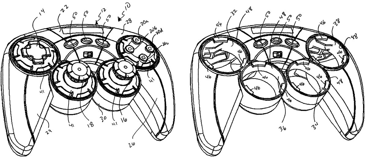
DETAILED DESCRIPTION OF THE INVENTION Referring toFIGS. 1-5, a video game controller10in accordance with the present embodiment generally includes a control pad or body12, a directional pad14, a right analog or tension stick16, a left analog or tension stick18and four action buttons20a-20d. Controller10is preferably used with a game system, such as, the PLAYSTATION, the PLAY STATION 2, the XBOX or the GAME CUBE; but can be used with any game system or computer system desired. Control pad12preferably has the general appearance and/or configuration of a conventional controller for a game system, such as the PLAY STATION 2, the XBOX or the GAME CUBE; however, the control pad can have any shape or configuration desired. The control pad preferably includes a body portion22, a first handle portion24and a second handle portion26, and is formed of an upper or top plastic housing28and a lower or bottom plastic housing30. Each portion of the controller12(including the control devices) is preferably molded plastic, but each individual portion formed from any suitable material. FIGS. 1 and 2illustrate the top plastic housing28, wherein the first handle generally supports directional control pad14, the second handle supports action buttons20a-20dand the body portion supports both the right analog stick (or joystick)16and the left analog stick (or joystick)18. However, as noted above, this positioning is not necessary and the control devices can be positioned in any manner desired. Furthermore, the game controller10can have any number of control devices disposed thereon. In other words, this invention is not limited to the specific number of action buttons, analog sticks and directional pads noted above, the present invention can have as many control devices (or as few) as desired and in any combination desired. The directional pad is preferably a substantially cross shaped pad that allows on screen directional movement along and x and ...
DETAILED DESCRIPTION OF THE INVENTION
Referring toFIGS. 1-5, a video game controller10in accordance with the present embodiment generally includes a control pad or body12, a directional pad14, a right analog or tension stick16, a left analog or tension stick18and four action buttons20a-20d. Controller10is preferably used with a game system, such as, the PLAYSTATION, the PLAY STATION 2, the XBOX or the GAME CUBE; but can be used with any game system or computer system desired.
Control pad12preferably has the general appearance and/or configuration of a conventional controller for a game system, such as the PLAY STATION 2, the XBOX or the GAME CUBE; however, the control pad can have any shape or configuration desired. The control pad preferably includes a body portion22, a first handle portion24and a second handle portion26, and is formed of an upper or top plastic housing28and a lower or bottom plastic housing30. Each portion of the controller12(including the control devices) is preferably molded plastic, but each individual portion formed from any suitable material.
FIGS. 1 and 2illustrate the top plastic housing28, wherein the first handle generally supports directional control pad14, the second handle supports action buttons20a-20dand the body portion supports both the right analog stick (or joystick)16and the left analog stick (or joystick)18. However, as noted above, this positioning is not necessary and the control devices can be positioned in any manner desired. Furthermore, the game controller10can have any number of control devices disposed thereon. In other words, this invention is not limited to the specific number of action buttons, analog sticks and directional pads noted above, the present invention can have as many control devices (or as few) as desired and in any combination desired.
The directional pad is preferably a substantially cross shaped pad that allows on screen directional movement along and x and a y axis and/or a combination thereof. However, the directional pad does not necessarily need to control direction on a screen and control any function desired or no function. Each of the analog sticks16and18are substantially similar and has a relatively narrow neck portion and a thumb or finger portion21. The analog sticks also can control movement in an x and y axis and/or a combination thereof, if desired; however as with the directional pad, the analog sticks do not necessarily need to control direction on a screen and control any function desired or no function. Additionally, the analog sticks can be adjustable tension sticks, if desired. The action buttons generally comprise four separate buttons that can control any on screen function or any function desired or no function. The actions buttons20a-dcan have individual markings thereon, if desired (e.g., a triangle, circle square, cross, etc.). It is noted that there does not need to be four action buttons, there can be as many action buttons (or as few) as desired. For example, there can be at least one action buttons or more, if desired.
The control pad12can have additional control devices extending through the lower housing30, such as triggers (not shown) disposed on the handle portions24and26.
As illustrated specifically inFIGS. 3 and 4, each of the control devices is removably coupled to the control pad12.FIG. 3shows the control pad12with each of the above described control devices removed therefrom. The control pad12has four substantially circular input control slots or positions32,34,36and38. As generally shown inFIGS. 1-3, control slot32has control device14positioned therein, control slot34has control device16positioned therein, control slot36has control device18disposed therein and control slot38has control devices20a-20ddisposed therein.
As shown inFIG. 3, each slot or input location32,34,36and38is preferably substantially circular and has three protrusions or locking mechanisms46. The protrusions are equally spaced around the inner wall or perimeter48, such that each protrusion is equidistant from both adjacent protrusions.
As shown inFIGS. 9-11, each control or module slot access the electrical circuitry with the control pad12and has eight electronic contacts or pins40a-hthat electrically connect or communicate with the electrical contacts on each specific control device. Electrical contacts40a-hare electrically connected to a printed circuit board (PCB) module43and a main printed circuit board (PCB)45. Through the main PCB45, the contacts are electrically coupled to a circuit or microprocessor42(FIG. 8) that is able to identify which specific control device is coupled or positioned in which specific slot.
Two contacts, such as40a-b, are connected to power ground and VCC, and the remaining 6 contacts,40c-h, are general purpose I/O pins. These general purpose I/O pins are preferably configured as analog to digital input or digital I/O pins. Contacts40c-fare preferably used as analog to digital input contacts and contacts40g-hare preferably used for reading module identification and can also be used for data communication if desired. These two contacts40g-hare preferably the control device specific identification tag. In other words, the microprocessor is able to determine which specific control device is in a control slot based on the unique identification on a specific control device. However, it is noted that this is only a preferred configuration and these contacts can be used in any suitable manner.
Below is a table that illustrates the preferred configuration of the contacts:
ModuleContactContactContactContactContactContactContactContactname40a40b40c40d40e40f40g (ID0)40h (ID1)Left stickVCCGNDX-axisY-axisL3LowHigh18Right StickVCCGNDX-axisY-axisR3HighHigh16D-Pad 14VCCGNDRightLeftUpDownHighLowActionVCCGNDTriangleCircleCrossSquareLowLowButtons20a-d
The microcontroller will read contacts40g-hof a module, thereby identifying the specific module, and will then have different handling methods for the analog values from contacts40c-eaccordingly. As noted in the table above, each contact is used to communicate specific information or control instructions to the microcontroller.
As shown inFIG. 8, each of the four modules is in electrical communication with an Analog-Digital & digital I/O bi-directional multiplexer44, along with fixed position analog buttons49, such as trigger buttons. The multiplexer then combines the signals sent from each module and transmits a single signal over one communications channel to a microprocessor or microcontroller42. Additionally, the signals from digital buttons50(for example, start, select and modes buttons) are transmitted directly to the microcontroller42. Each of these signals is processed in the microcontroller, which then sends the appropriate control signal to the game console57and/or a signal to the vibrating mechanism53in the controller and an LED indicator55in the controller. It is noted that it is not necessary to have a vibrating mechanism and/or an LED indicator in the controller. Additionally, it is noted that the controller does not necessarily need to use a microcontroller. The controller can use any electrical circuitry or any other system suitable.
Each control device has a substantially circular module41that couples into a respective control slot and holds and secures the control device in its proper position relative to the respective control slot. Each control device module has an electronic identification that communicates to the microprocessor, through the contacts40a-hin a respective control slot, which control device is coupled in which slot.
Each module41has an outer surface50that has approximately the same diameter as the diameter of the slots32,34,36and38, and is sized and configured to fit therewithin. Each module41has three protrusions52extended from outer surface50. Protrusions52are each equidistant from each other such that each protrusion is an equal distance form both of the adjacent protrusions. Protrusions52are sized and configured to couple and frictionally lock with each of the protrusions46in the slots38. The coupling mechanism between the module41and slots32-38is preferably a twist and lock connection, but it can be any suitable connection.
Operation
As shown inFIGS. 1-7a first control device, for example directional pad14(or the action buttons or the left and right analog sticks) and its respective module41is removed from a slot, for example32by twisting the module relative to the slot and disengaging the protrusion52on the module with the protrusions46on the slot. As stated above, it is not necessary to have a twist and lock coupling mechanism as described herein. The coupling mechanism can be any method or mechanism suitable. For example, the mechanism can be simple friction, a latching mechanism, a magnetic connection, or any other connection desired.
A second or additional control device, for example right and left analog sticks16and18and action buttons20a-d, and their respective modules41, can be removed or disengaged from their respective slots in the same manner as above. Each of these modules can then be placed in a different random or preselected position (i.e., each of the four input or control devices can be removably coupled to each or any of the four input slots or locations). For example, right analog stick16can be positioned in slot38and directional control pad14can be placed in slot34, as shown inFIG. 12Each of these modules are inserted into the selected slot and then twisted to lock in place, such that protrusion52frictional engages protrusion46.
The contacts on the individual control device module relay the specific control device information (i.e., the proper identification and the control input from the user) and electrically couple to the contacts40a-hin a slot, thus allowing communication with the microprocessor, which in turn communicates with the game system or other portions of the controller.
Once each module is positioned in the selected slot, the respective controls operate in their normal prescribed manner, that is the analog stick that is meant to operate a specific function, still operates that function, the directional control pad that was meant to operate a certain function still operates that game specific function, etc. The placement of the specific controls merely changes, not their intended usage. This change of placement allows the user to specifically set up the controls to a preferred location. It is noted however, that that it is not necessary for each control to have its specific function follow it to a new location. In other words, it is possible that the on screen function remain at a specific location or with a specific slot or that the on screen function can be programmed to any slot desired, independent of the module inserted therein.
It should be understood that various changes and modifications to the presently preferred embodiments described herein will be apparent to those skilled in the art. Such changes and modifications can be made without departing from the spirit and scope of the present invention and without diminishing its intended advantages. It is therefore intended that such changes and modifications be covered by the appended claims.
Claims
- A game controller, comprising: a body configured to be hand-held;a first input location;a second input location, wherein the first and second input locations are substantially symmetrically disposed on the body;a first finger actuatable control device configured to be removably coupled to the body and adapted to be identified by at least one of the first input location and the second input location and configured such that finger actuation of the device controls game activity;and an electrical circuit coupled to and configured to determine an identity of the control device.
- A game controller according to claim 1 , further including a second finger actuatable device adapted to be removably coupled to the body at both first input location and said second input location.
- A game controller according to claim 1 , wherein said first finger actuatable device is selected from the group consisting of a joystick, a directional control pad and at least one action button.
- A game controller according to claim 1 , wherein said first finger actuatable device is an adjustable tension stick.
- A game controller according to claim 1 , wherein said first finger actuatable device includes an identification tag that enables at least one of the first and second input locations to identify the first finger actuatable device.
- A game controller according to claim 1 , wherein said first and second input locations include electrical contacts adapted to couple to said first finger actuatable device.
- A game controller according to claim 1 , wherein the electrical circuit includes a microprocessor.
- A game controller according to claim 1 , wherein the electrical circuit includes a microcontroller.
- A game controller according to claim 2 , wherein said first finger actuatable device is selected from the group consisting of a joystick, a directional control pad and at least one action button.
- A game controller according to claim 2 , further including a third input location;a fourth input location;a third finger actuatable device;and a fourth finger actuatable device;wherein each of said first, second, third and fourth finger actuatable devices is adapted to be removably coupled to said body in each of said first, second, third and fourth input locations.
- A game controller according to claim 9 , wherein said second finger actuatable device is selected from the group consisting of a joystick, a directional control pad and at least one action button.
- A device for controlling actions in an electronically based medium, comprising: a hand-held control pad having electrical circuitry therein;a first slot in said control pad configured to allow access to said electrical circuitry;a second slot in said control pad configured to allow access to said electrical circuitry, wherein the first and second slots are substantially symmetrically disposed on the control pad;a first device configured to couple to said electrical circuitry and identified by insertion into at least one of said first input slot or said second input slot and configured to be associated with controlling actions in the electronically based medium;a second device configured to couple to said electrical circuitry by insertion into at least one of said first input slot or said second input slot and configured to be associated with controlling actions in the electronically based medium;and a microprocessor configured to couple to the electrical circuitry and to determine an identity of the first control device.
- A device according to claim 12 , wherein said first device is a joystick;and said second device is a directional pad.
- A device according to claim 12 , wherein said first device is an adjustable tension stick.
- A device according to claim 12 , wherein said first device includes an identification tag that enables at least the first slot to identify the first device.
- A device according to claim 12 , wherein said first and second slots include electrical contacts adapted to couple to said first and second devices.
- A game controller according to claim 12 , further including a third slot;a fourth slot;a third device;and a fourth device;wherein each of said first, second, third and fourth devices is adapted to be removably coupled to said body in each of said first, second, third and fourth slots.
- A method for using a hand-held game controller having a first input device, a second input device, a first input location and a second input location, wherein the first and second input locations are substantially symmetrically disposed on the game controller, comprising: removing the first input device from the first input location;inserting the first input device to the second input location;inserting the second input device to the first input location;identifying with an electrical circuit at least the first input device by insertion into at least one of the input locations;and manipulating each of said first and second input devices to affect game activity.
- A method according to claim 18 , wherein the first input device is a joystick;and the second input device is a directional control pad.
- A method according to claim 18 , further including the step of: for each of said input devices, identifying the input device using an associated identification tag if the input device is inserted into one of the input locations.
- A method according to claim 18 , further including the step of using electrical contacts in the first and second input locations adapted to couple the first input device to the first or second input location.
- A method according to claim 18 , further including the step of removing the second input device from the second input location.
- The method of claim 18 , wherein the electrical circuit includes a microprocessor.
- The method of claim 18 , wherein the electrical circuit includes a microcontroller.
- A method according to claim 19 , wherein the first input device is selected from the group consisting of a joystick and a directional control pad;and the second input device is at least one action button.
- A game controller, comprising: a hand-held body having electrical circuitry therein;a first device having a first unique identification tag, wherein the first device is located at a first location on said body and electrically coupled to said electrical circuitry;and a second device having a second unique identification tag, wherein the second device is located at a second location on said body, and wherein the first and second locations are substantially symmetrically disposed on the body, wherein the electrical circuitry is adapted to allow selective control of a specific function between said first device and said second device, and wherein at least one of the first and second devices is adapted to be identified by the electrical circuit by the unique identification tag of the device in at least one of the first and second locations.
- The game controller of claim 26 , wherein the electrical circuit includes a microprocessor.
- The game controller of claim 26 , wherein the electrical circuit includes a microcontroller.
- A game controller, comprising: a hand-held body having electrical circuitry therein;at least one input button module positioned on said body and electrically coupled to said electrical circuitry;a microprocessor coupled to the electrical circuitry;and at least one joystick having a unique identification tag, wherein said joystick is positionable in a first location and a second location relative to said at least one input button, wherein the at least one joystick is adapted to be identified by the microprocessor by its unique identification tag in at least one of the first and second locations, and wherein the first and second locations are substantially symmetrically disposed on the body.
- A game controller according to claim 29 , wherein said at least one input button module is subdivided into at least four separate input buttons.
- A game controller according to claim 29 , wherein said at least one joystick is electrically coupled to said electrical circuitry.
- A game controller according to claim 29 , wherein said at least one joystick is electrically coupled to said electrical circuitry using electrical contacts.
- A device for controlling a game system, comprising: a body configured to be hand held and having an electrical circuit;an opening in said body having contacts for the electrical circuit;a first finger actuatable device configured to couple to said electrical circuit;and a second finger actuatable device configured to couple to said electrical circuit, wherein said opening is configured to allow selective use of either said first finger actuatable device or said second finger actuatable device, wherein each of the finger actuatable devices includes a substantially circular housing configured to be insertable and rotatably lockable to and removable from the body, and wherein at least one of the first and second finger actuatable devices is adapted to be identified in the opening of the body by the electrical circuit.
- A device according to claim 33 , wherein said first finger actuatable device is at least one button;and said second finger actuatable device is a joystick.
- The device of claim 33 , wherein the first finger actuatable device has a first unique identification tag, wherein the second finger actuatable device has a second unique identification tag, and wherein the electrical circuit includes a microprocessor configured to identify at least one of the first and second finger actuatable devices by its identification tag.
- A module for use with a multimedia controller, comprising: a body configured to be finger actuatable and including a substantially circular housing configured to be insertable and rotatably lockable to and removable from the multimedia controller;an identification tag coupled to the housing that enables the multimedia controller to identify the module;and an electrical circuit coupled to the multimedia controller, wherein the electrical circuit is configured to identify the module based on its identification tag.
- A module according to claim 36 , wherein the module is configured to control multimedia activity based on finger actuation.
- A module according to claim 36 , wherein said module is selected from the group consisting of a joystick, a directional control pad and at least one action button.
- The module of claim 36 , wherein the electrical circuit includes a microcontroller.
- The module of claim 36 , wherein the electrical circuit includes a microprocessor.
Disclaimer: Data collected from the USPTO and may be malformed, incomplete, and/or otherwise inaccurate.