U.S. Pat. No. 7,753,788
GAME CONTROLLER THAT CONVERTS BETWEEN WIRELESS OPERATION AND WIRED OPERATION
AssigneeMicrosoft Corporation
Issue DateJanuary 30, 2004
Illustrative Figure
Abstract
A game controller operates in both a wired mode and a wireless mode, and is able to switch between these two modes without permanent disruption to an ongoing game. During a transition from one mode to another, a host gaming system detects when the controller is physically disconnected (for wired mode to wireless mode) or connected (for wireless mode to wired mode). Upon detection, the host gaming system stores the game data and user information and the game controller stores an identifier in its nonvolatile memory. The host gaming system and game controller then establish a new communication link. The game controller retrieves the identifier and submits it to the host gaming system, which uses the identifier to reassociate the game data and user information with the game controller as it begins operating in the new mode. This allows the player to continue game play without interruption.
Description
DETAILED DESCRIPTION The following disclosure describes a game controller that can be operated in both a wired mode and a wireless mode. The game controller can switch easily between the two modes without disrupting continued play of the game. For discussion purposes, the game controller is described in the context of a multi-purpose game controller for a console-based gaming system. However, the game controller may be configured in many different ways and with a wide variety of functionality, including specialty controllers. Gaming System FIG. 1shows an exemplary console-based gaming system100. It includes a game console102and up to four controllers, as represented by two controllers104(1) and104(2). Each controller104is coupled to the game console102via a wire or wireless interface and utilizes a suitable data protocol, such as USB (Universal Serial Bus). One controller104(2) is illustrated as operating in two different modes: a wired mode and a wireless mode. In the wired mode, the controller104(2) is connected to the game console102via a cable106. The controller derives power from the game console through the cable106. In the wireless mode, the controller104(2) is connected to the game console102via a wireless link108. The wireless link may be implemented using any one of many different technologies including, for example, infrared, Bluetooth, or RF technologies. In the wireless mode, the controller104(2) draws from its own power source, such as a battery. The cable106may optionally be detached from the controller to offer more freedom of movement. The player can switch between wireless operation and wired operation by connecting the serial cable106to, or disconnecting it from, the game console102. Mode-switching may occur during game play without interrupting the game. For example, if a game controller is in wireless mode and the battery runs low during game play, the player may switch to wired mode by plugging the cable106into the game ...
DETAILED DESCRIPTION
The following disclosure describes a game controller that can be operated in both a wired mode and a wireless mode. The game controller can switch easily between the two modes without disrupting continued play of the game. For discussion purposes, the game controller is described in the context of a multi-purpose game controller for a console-based gaming system. However, the game controller may be configured in many different ways and with a wide variety of functionality, including specialty controllers.
Gaming System
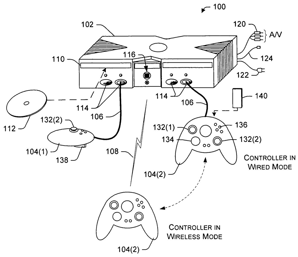
FIG. 1shows an exemplary console-based gaming system100. It includes a game console102and up to four controllers, as represented by two controllers104(1) and104(2). Each controller104is coupled to the game console102via a wire or wireless interface and utilizes a suitable data protocol, such as USB (Universal Serial Bus). One controller104(2) is illustrated as operating in two different modes: a wired mode and a wireless mode. In the wired mode, the controller104(2) is connected to the game console102via a cable106. The controller derives power from the game console through the cable106. In the wireless mode, the controller104(2) is connected to the game console102via a wireless link108. The wireless link may be implemented using any one of many different technologies including, for example, infrared, Bluetooth, or RF technologies. In the wireless mode, the controller104(2) draws from its own power source, such as a battery. The cable106may optionally be detached from the controller to offer more freedom of movement.
The player can switch between wireless operation and wired operation by connecting the serial cable106to, or disconnecting it from, the game console102. Mode-switching may occur during game play without interrupting the game. For example, if a game controller is in wireless mode and the battery runs low during game play, the player may switch to wired mode by plugging the cable106into the game console102and game play continues without interruption. While in wired mode, the game controller is powered by the game console and the controller battery is recharged.
The game console102is equipped with a portable media drive110and an optional internal hard disk drive. The portable media drive supports various forms of portable storage media as represented by an optical storage disc112. Examples of suitable portable storage media include DVD, CD-ROM, game discs, game cartridges, and so forth.
The game console102has four slots114on its front face to support up to four controllers, although the number and arrangement of slots may be modified. In the wired mode, the game controllers104are assigned to the physical slots114for controlling various characters/features of the video game. In wireless mode, however, the game controllers104(1)-104(4) are assigned to virtual slots.
In one implementation, virtual slots are assigned, without prompting the user, in sequential order to reduce complexity for the user. Thus, the first virtual slot is assigned to the first wireless game controller introduced to the host game console102; the second virtual slot is assigned to the second wireless game controller, and so on. Alternatively, the user can choose a virtual slot via a user interface presented on the display. Actuation of a pre-designated button on the console invokes a slot assignment pane from which the player can select an available virtual slot.
Control buttons116are positioned on the front face of the game console102. Control buttons116include, for example, a power button that switches power to the game console and an eject button that alternately opens and closes a tray of the portable media drive110to allow insertion and extraction of the storage disc112.
The game console102connects to a television or other display (not shown) via A/V interfacing cables120. A power cable122provides power to the game console. The game console102may be further equipped with internal or externally added network capabilities, as represented by the cable or modem connector124to facilitate access to a network, such as a local area network (LAN) or the Internet.
Each controller104may be equipped with any of a wide variety of user interaction mechanisms. As illustrated inFIG. 1, each controller104is equipped with two thumbsticks132(1) and132(2), a directional or D-pad134, surface buttons136, and two triggers138. These mechanisms are merely representative, and other known gaming mechanisms (e.g., shoulder buttons) may be substituted for or added to those shown inFIG. 1.
A memory unit (MU)140may be inserted into the controller104to provide additional and portable storage (as illustrated) or alternatively into the game console102. Portable memory units enable users to store game parameters and transport them for play on other consoles. In the illustrated implementation, each controller is configured to accommodate two memory units140, although more or less than two units may be employed in other implementations. In other implementations, the game console may support one or more memory units per player.
FIG. 2shows functional components of the gaming system100in more detail. The game console102has a central processing unit (CPU)200and a memory controller202that facilitates processor access to various types of memory, including a flash ROM (Read Only Memory)204, a RAM (Random Access Memory)206, a hard disk drive208, and the portable media drive106. The CPU200is equipped with a level 1 cache210and a level 2 cache212to temporarily store data and hence reduce the number of memory access cycles, thereby improving processing speed and throughput.
The CPU200, memory controller202, and various memory devices are interconnected via one or more buses, including serial and parallel buses, a memory bus, a peripheral bus, and a processor or local bus using any of a variety of bus architectures. By way of example, such architectures can include an Industry Standard Architecture (ISA) bus, a Micro Channel Architecture (MCA) bus, an Enhanced ISA (EISA) bus, a Video Electronics Standards Association (VESA) local bus, and a Peripheral Component Interconnect (PCI) bus.
As one suitable implementation, the CPU200, memory controller202, ROM204, and RAM206are integrated onto a common module214. ROM204is configured as a flash ROM that is connected to the memory controller202via a PCI (Peripheral Component Interconnect) bus and a ROM bus (neither of which are shown). RAM206is configured as multiple DDR SDRAM (Double Data Rate Synchronous Dynamic RAM) modules that are independently controlled by the memory controller202via separate buses (not shown). The hard disk drive208and portable media drive106are connected to the memory controller via the PCI bus and an ATA (AT Attachment) bus216.
A 3D graphics processing unit220and a video encoder222form a video processing pipeline for high speed and high resolution graphics processing. Data is carried from the graphics processing unit220to the video encoder222via a digital video bus (not shown). An audio processing unit224and an audio codec (coder/decoder)226form a corresponding audio processing pipeline with high fidelity and stereo processing. Audio data is carried between the audio processing unit224and the audio codec226via a communication link (not shown). The video and audio processing pipelines output data to an A/V (audio/video) port228for transmission to the television or other display. In the illustrated implementation, the video and audio processing components220-228are mounted on the module214.
Also implemented on the module214are a USB host controller230and a network interface232. The USB host controller230is coupled to the CPU200and the memory controller202via a bus (e.g., PCI bus) and serves as host for the peripheral controllers104(1)-104(4). The network interface232provides access to a network (e.g., LAN, Internet, etc.) and may be any of a wide variety of various wired or wireless interface components including an Ethernet card, a modem, a Bluetooth module, a cable modem, and the like.
The game console102has two dual controller support subassemblies240(1) and240(2), with each subassembly supporting up to two of the game controllers104(1)-104(4). A front panel I/O subassembly242supports the functionality of the control buttons116, as well as any LEDs (light emitting diodes) or other indicators exposed on the outer surface of the game console. A controller wireless interface244is also provided to support wireless communication with the game controllers. The wireless interface244may use any one of many technologies, including IR, Bluetooth, and RF technologies. The subassemblies240(1),240(2), and242and controller wireless interface244are coupled to the module214, and particularly the USB controller230, via one or more cable assemblies246.
Eight memory units140(1)-140(8) are illustrated as being connectable to the four controllers104(1)-104(4), i.e., two memory units for each controller. Each memory unit140offers additional storage on which games, game parameters, and other data may be stored. When inserted into a controller, the memory unit140can be accessed by the memory controller202. It is noted that, in other implementations, the memory units140may be inserted into compatible slots in the game console102.
A system power supply module250provides power to the components of the gaming system100and to the game controllers104when operating in the wired mode. A fan252cools the circuitry within the game console102.
The game console102may further implement a cryptography engine to perform common cryptographic functions, such as encryption, decryption, authentication, digital signing, hashing, and the like. The cryptography engine may be implemented as part of the CPU200, or in software stored in memory (e.g., ROM204, hard disk drive208) that executes on the CPU, so that the CPU is configured to perform the cryptographic functions.
Game data260generated during game play is stored in memory at the game console, such as in hard disk drive208(although other storage may be used). The type and quantity of game data is game specific and can be essentially anything that a game developer would like to track. Examples of game data might include skid marks or fuel level in a racing game, weapon selection or life count in shooter games, and so forth.
The game data260is stored in relation to a controller ID262. When a player switches between wired and wireless mode of operation, the controller passes in the controller ID and the console tries to match it with any controller IDs stored on hard disk drive208in relation to saved game data260. If a match is found, the game console reassociates the corresponding game data with the controller.
FIG. 3shows functional components of the game controller104in more detail. The controller104has a central processing unit (CPU)302and memory, including ROM304, RAM306and EEPROM308. In the illustrated implementation, the CPU302, ROM304, and RAM306are integrated onto a common module310and are interconnected via one or more bussing structures. EEPROM308is separate from, but interfaced with, the module310.
The game controller104further includes motor drives312to provide tactile feedback to the player and a PWM (pulse width modulation) output314to provide the control signals for the motor drives. Player actions received via variable-input actuators316(e.g., thumbsticks132and triggers138) are converted by analog-to-digital converter (ADC)318to provide player input to the CPU302. ADC318can be implemented, for example, as an eight channel 10-bit or 12-bit converter. Other player actions received through dual-state switches320(e.g., buttons136and D-pad134) are passed through I/O322to CPU302.
As noted above, the game controller104supports both wired operation and wireless operation. The game controller104includes a USB interface330and USB connector332for the wired mode of operation. In the illustrated implementation, the game controller104is configured to support wireless operation using RF (radio frequency) technologies. An RF module334(e.g., 2.4 GHz RF module), a radio baseband unit336, and DMA (Direct Memory Access) channels unit338support the wireless mode of operation. In other implementations, the game controller can be designed to utilize alternative wireless technologies, such as IR (infrared), Bluetooth, UWB (UltraWide Band), and so forth.
The game controller104is equipped with its own power source to enable wireless operation. In the illustrated implementation, a battery350supplies power to the electronic modules and components of the game controller104. A battery power controller352monitors the battery350and detects when power is low. Upon detection, a low power condition can be conveyed to the player (e.g., illumination of a light indicator on the controller or display of a warning while the game is being played). The player can then switch to wired mode by plugging in the cable to the game console. The battery power controller352also monitors charging behavior of the battery, such as how long it takes to charge and detection of when it is fully charged. In wired mode, the game controller104receives power from the game console. A battery charging circuit354recharges battery350while the controller is connected via the cable. A reset circuit358and power on reset circuitry360allow the game controller to be reset during operation or when power is initially provided. A power management module356generates voltages for the different components on the module310and dynamically manages power consumption of those components.
As part of the power management, the console maintains battery life data including, for example, the total life expectancy of the battery, how much power has been drawn during wireless play, and the amount of time left before the battery supply is effectively depleted. The controller sends the battery life data to the console and the console can utilize the data to instruct the player when to switch from wireless play to wired play so that the controller can be recharged. For instance, the console may flash a warning light on the console or present a pop up message on the display to inform the player of low battery conditions and suggest that the player plug the controller cable into the console for continued play.
A voice module370may be optionally included in the game controller104to receive oral commands or speech from the player. The game controller104also has timing components to provide timing functionality, including a general purpose timer374(e.g., 16-bit timer), a watchdog timer376, an oscillator378, and a crystal380.
One or more identifiers390are stored in EEPROM308. In particular, the EEPROM308stores a session ID that is used to facilitate switching between wired mode and wireless mode without causing permanent disruption to game play. The session ID includes an active game ID that identifies the current virtual slot being used by the controller and a device ID that identifies the controller itself. After a mode transition occurs (i.e., from wired mode to wireless mode, or vice versa) and a new connection is established, the game controller104passes the session ID to the game console. The game console extracts the controller ID portion and looks to match it with any controller ID stored on the game console in relation to saved game data. If a match is found, the game console reassociates the corresponding game data with the controller. In this manner, game play can continue uninterrupted during transition from wireless mode to wired mode.
Mode Switching Operation
FIG. 4shows a process400for switching a game controller from a wireless mode of operation to a wired mode of operation. The process400is illustrated as a collection of blocks in a logical flow graph, which represent a sequence of operations that can be implemented in hardware, software, or a combination thereof. In the context of software, the blocks represent computer instructions that, when executed by one or more processors, perform the recited operations.
The process includes operations performed by both the game controller and a host gaming system. For discussion purposes, the process400is described with reference to the controller104and game console102described above with respect toFIGS. 1-3. It is noted that the process400may be implemented by other types of controllers that are designed for both wired and wireless communication, and for other types of gaming systems, such as PCs.
At block402, the game controller104is operated in a wireless mode. In this mode, the game controller104draws power from the battery350and transmits user commands via the RF module334to the game console104. During operation in wireless mode, the game controller104monitors for conditions that might suggest a switch in operation from wireless mode to wired mode (block404). One example of a condition is where battery power controller352detects that battery350is running low. Another example condition occurs when a number of packets are lost or otherwise contain incorrect data during the wireless exchange between the controller104and console102, perhaps due to a noisy RF environment or other interference. If no such conditions arise (i.e., the “No” branch from block404), the game controller remains in wireless mode.
When a transition condition is detected (i.e., the “Yes” branch from block404), the game controller104determines whether the session ID is saved in memory resident at the controller (block406). The session ID includes an active game ID that identifies the current virtual slot being used by the controller and a device ID that identifies the controller. If the session ID is not saved (i.e., the “No” branch from block406), the game controller104saves the session ID in nonvolatile memory resident at the controller, such as EEPROM308(block408).
Once the session ID is saved on the controller, the host (e.g., game console102) determines whether the cable106is connected to one of the physical slots114(block410). If not (i.e., the “No” branch from block410), the game controller104continues to be operated in wireless mode. It may continue in this mode until the cable is attached or the battery ceases to supply sufficient power. When the cable is connected (i.e., the “Yes” branch from block410), the game console102performs USB enumeration to establish a USB connection via the cable106(block412).
Once the connection is established, the game controller104retrieves the session ID from nonvolatile memory and sends it to the game console (block414). The game console uses the session ID to locate any saved game data and reassociates that game data with the controller (block416). More particularly, as game data260is generated during play, it is stored at the game console102in relation to a controller ID262associated with the game controller. The controller ID may be unique to the controller itself or it may represent a connection slot currently being used by the controller. When a mode transition occurs (i.e., from wired mode to wireless mode, or vice versa), the game console uses the controller ID from the session ID received from the newly attached game controller and looks to match it with any controller ID stored on the game console. If a match is found, the game console reassociates the game data for the active game identified in the session ID with the controller. In this manner, game play can continue uninterrupted during transition from wireless mode to wired mode. At block418, the game controller104continues in wired mode.
FIG. 5shows a process500for switching a game controller from a wired mode of operation to a wireless mode of operation. The process includes operations performed by both the game controller and a host gaming system, and once again will be described with reference to the controller104and game console102described above with respect toFIGS. 1-3.
At block502, the host (e.g., game console102) performs USB enumeration to establish a USB connection with the game controller104via the cable106. Once a connection is established, the game controller104is operated in the wired mode (block504). At block506, the game controller104determines whether the session ID is saved in controller memory. If the session ID is not saved (i.e., the “No” branch from block506), the game controller104saves the session ID in nonvolatile memory, such as EEPROM308(block508).
Once the session ID is saved on the controller, the game controller104determines whether the cable106remains connected to one of the physical slots114of the game console (block510). If it is still connected (i.e., the “Yes” branch from block510), the game controller104continues to be operated in wired mode. When the cable is disconnected (i.e., the “No” branch from block510), the game controller104performs a discovery process to become part of a wireless network and establish a wireless connection between the game controller and the game console (block512).
Once a wireless connection is established, the game controller104retrieves the session ID from its nonvolatile memory and sends it to the game console so that any on-going game data can be reassociated with the controller (block514). At block516, the game controller104continues to operate in wireless mode.
The described mode switching processes400and500also accommodate the situation where a new player joins a game. A new player can connect his/her game controller to an available physical slot for wired operation or begin operation directly in wireless mode using the discovery process. The game console first attempts to match the session ID with a current list of session IDs. When a match is not found, the game console associate that device ID with the physical or virtual slot through which it communicates. It can then begin storing game data in relation to that device ID.
CONCLUSION
The above-described game controller facilitates both wired and wireless operation and the ability to switch between wired and wireless operation without interrupting an ongoing game. Although the invention has been described in language specific to structural features and/or methodological acts, it is to be understood that the invention defined in the appended claims is not necessarily limited to the specific features or acts described. Rather, the specific features and acts are disclosed as exemplary forms of implementing the claimed invention.
Claims
- A video game controller comprising: a processor;a memory coupled to the processor;a first module to support communication over a cable for wired operation;a second module to support communication over a wireless link for wireless operation;a battery to supply power to the processor, the memory, and the second module when the video game controller is in wireless operation;and a power management module to maintain battery life data to be communicated to a host game system, the battery life data including: a total life expectancy of the battery;power used during wireless operation;and an amount of time left before battery supply is depleted;wherein the memory stores an identity of the video game controller;and when transitioning between the first and second modules in order to support communication, the video game controller passes the identity to the host game system for use in maintaining an association between the video game controller and game data of a video game currently being played to facilitate continued play of the video game, wherein the video game controller and the game data are associated with one another both before and after the transition.
- A video game controller as recited in claim 1 , wherein the second module comprises an RF module to support RF communication.
- A video game controller as recited in claim 1 , further comprising charging circuitry to charge the battery when the video game controller is in wired operation.
- A video game controller as recited in claim 1 , wherein the host name system comprises one of a game console or a personal computer.
- A video game controller as recited in claim 1 , comprising: a serial cable to connect the host game system;and a wireless interface to communicate with the host game system when the cable is detached from the host game system.
- A method implemented by a host game system comprising: during play of a video game, receiving an identifier associated with a video game controller;associating the identifier with game data of the video game, wherein the game data of the video game is specific to the video game controller;detecting when conditions of the video name controller suggest switching from a wireless mode of operation to a wired mode of operation based on monitoring maintenance of battery life data, the battery life data including: a total life expectancy of a battery;power used during the wireless mode of operation;and an amount of time left before battery supply is depleted;conveving a low power indication based on the suggestion;switching the video game controller from the wireless mode of operation to the wired mode of operation;and continuing to facilitate uninterrupted play of the video game by communicating with the video game controller via the wired mode of operation, such that the identifier, which is associated with the video game controller and which is also associated with the game data of the video game that is specific to the video game controller, is used to maintain the association between the game data and the video game controller while the video game controller transitions from the wireless mode of operation to the wired mode of operation.
- For use with a video game system, a storage medium having instructions that, when executed on the video game system, performs acts comprising: receiving instructions for controlling a video game from one of a plurality of video game controllers, the instructions being transmitted over a cable in a wired mode of operation and the instructions being transmitted over a wireless link in a wireless mode of operation;storing game data for the video game in association with an identity of each of the plurality of video game controllers, the game data being associated with a particular one of the plurality of video game controllers representing a particular game entity controlled by the particular one of the plurality of video game controllers;detecting when conditions of the particular one of the plurality of video game controllers suggest switching from the wireless mode of operation to the wired mode of operation based on monitoring maintenance of battery life data, the battery life data including: a total life expectancy of a battery;power used during the wireless mode of operation;and an amount of time left before battery supply is depleted;conveying a low power indication;facilitating transition from the wireless mode of operation to the wired mode of operation;and using the identity of the particular one of the plurality of video game controllers to switch from the wireless mode of operation the wired mode of operation to reassociate the game data, enabling ongoing play of the video game.
- A storage medium as recited in claim 7 , wherein the detecting comprises sensing when the cable is disconnected from the video game system.
Disclaimer: Data collected from the USPTO and may be malformed, incomplete, and/or otherwise inaccurate.