U.S. Pat. No. 7,704,146
MULTIPLY INTERCONNECTABLE ENVIRONMENTALLY INTERACTIVE CHARACTER SIMULATION MODULE METHOD AND SYSTEM
AssigneeMattel, Inc.
Issue DateApril 7, 2008
U.S. Patent No. 7,704,146: Multiply interconnectable environmentally interactive character simulation module method and system

Summary:
The ‘146 patent describes a hand held game much like the Tamagotchi toys that were popular over the past ten years. The system described here involves two systems which can be electrically connected to each other. The first character has different traits than the second one. The two characters have their own screens (operated by different players), but when the two systems are connected both characters appear and interact on the same screen.
Abstract:
The present invention relates to a game, including a first module having a housing, a processor, a display operably coupled to the processor and an electrical contact positioned such that access is available to the electrical contact of the first module through the first module housing, and a second module having a housing, a processor, a display operably coupled to the processor and an electrical contact positioned such that access is available to the electrical contact of the second module through the second module housing, the electrical contact of the second module configured to contact the electrical contact of the first module, allowing the processor of the first module to communicate with the processor of the second module. Wherein when the processor of the second module is in communication with the processor of the first module, the first module display and the second module display are configured to each display a portion of a the game, each such portion configured to not overlap each other such portion.
Illustrative Claim:
1. A game, comprising: a first module having a first electrical contact, a first processor and a first display, the processor configured to display a first character on the display, the character having a first set of traits; and a second module having a second electrical contact, a second processor and a second display, the processor configured to display a second character on the display, the character having a second set of traits; wherein the first electrical contact and second electrical contact are configured to electrically couple in two or more interconnection configurations, each interconnection configuration allowing the first and second processors to communicate, wherein the processor is programmed to display a first animation sequence if the first module and the second module are arranged in a first interconnection configuration, and wherein the processor is programmed to display a second animation sequence if the module and the second module are arranged in a second interconnection configuration, the second interconnection configuration being different from the first interconnection configuration, the second animation sequence being different from the second animation sequence.
Illustrative Figure
Abstract
The present invention relates to a game, including a first module having a housing, a processor, a display operably coupled to the processor and an electrical contact positioned such that access is available to the electrical contact of the first module through the first module housing, and a second module having a housing, a processor, a display operably coupled to the processor and an electrical contact positioned such that access is available to the electrical contact of the second module through the second module housing, the electrical contact of the second module configured to contact the electrical contact of the first module, allowing the processor of the first module to communicate with the processor of the second module. Wherein when the processor of the second module is in communication with the processor of the first module, the first module display and the second module display are configured to each display a portion of a the game, each such portion configured to not overlap each other such portion.
Description
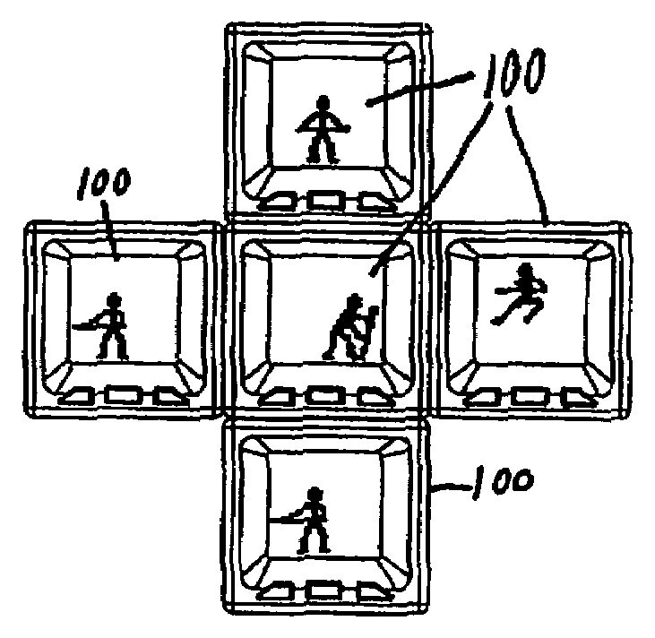
DETAILED DESCRIPTION In one embodiment of the present invention, a character simulation module is interconnectable with one or more other character simulation modules. Preferably, the module is directly interconnectable with up to four other character modules and indirectly interconnectable with an unlimited number of other modules, but the limit for directly and indirectly interconnected modules can be any suitable number. As illustrated byFIGS. 1A and 1B, the character simulation module100is preferably substantially cube-shaped; however, the module can be any suitable shape. Further, the module100is preferably suitably sized to be hand-held (e.g., 40 mm×40 mm×40 mm, or 47 mm×47 mm×47 mm), but can be any suitable size. At least one surface110(e.g., a front surface) of the module100includes a display120. The display120is preferably a 32×32 pixel dot matrix liquid crystal display (LCD) approximately 25 mm×25 mm in size, but the display120can be of any suitable type, resolution and size. Further, the module100has input devices130that enable a user to interact with the module100. Communication devices140are located on one or more surfaces150(e.g., a top, left, right and bottom surface) that enable the module100to interconnect with other modules. Preferably, the communication devices140and the display120are not on the same surface; however, communication devices140can be positioned on the same surface as the display120. When another module is interconnected with the module100, communication devices140preferably form a physical connection with the communication devices of the other module. Communication devices140are preferably flat metal connectors, but can be either male or female connectors which both connect two modules and help hold those modules in an interconnected position. Alternatively, communication devices140can communicate wirelessly (e.g., via IR, RF, other light or sonic transmissions), and can be located on the interior of the module100rather than at any surface. As shown inFIG. 2, modules100can be interconnected. Preferably, modules can only be connected in certain configurations. ...
DETAILED DESCRIPTION
In one embodiment of the present invention, a character simulation module is interconnectable with one or more other character simulation modules. Preferably, the module is directly interconnectable with up to four other character modules and indirectly interconnectable with an unlimited number of other modules, but the limit for directly and indirectly interconnected modules can be any suitable number.
As illustrated byFIGS. 1A and 1B, the character simulation module100is preferably substantially cube-shaped; however, the module can be any suitable shape. Further, the module100is preferably suitably sized to be hand-held (e.g., 40 mm×40 mm×40 mm, or 47 mm×47 mm×47 mm), but can be any suitable size. At least one surface110(e.g., a front surface) of the module100includes a display120. The display120is preferably a 32×32 pixel dot matrix liquid crystal display (LCD) approximately 25 mm×25 mm in size, but the display120can be of any suitable type, resolution and size. Further, the module100has input devices130that enable a user to interact with the module100.
Communication devices140are located on one or more surfaces150(e.g., a top, left, right and bottom surface) that enable the module100to interconnect with other modules. Preferably, the communication devices140and the display120are not on the same surface; however, communication devices140can be positioned on the same surface as the display120. When another module is interconnected with the module100, communication devices140preferably form a physical connection with the communication devices of the other module. Communication devices140are preferably flat metal connectors, but can be either male or female connectors which both connect two modules and help hold those modules in an interconnected position. Alternatively, communication devices140can communicate wirelessly (e.g., via IR, RF, other light or sonic transmissions), and can be located on the interior of the module100rather than at any surface.
As shown inFIG. 2, modules100can be interconnected. Preferably, modules can only be connected in certain configurations. For example, a top side of one module can be connectable only to a bottom side of another module and not any other side of that module.FIGS. 3A and 3Bshow examples of correct and incorrect, respectively, module100interconnection when modules100are only connectable in certain configurations. InFIG. 3A, each of the illustrated interconnection configurations is permitted. In contrast, inFIG. 3B, none of the interconnections configurations illustrated are permitted.
Alternatively, modules can be interconnected in any configuration, if desired. For example, any side of one module can be connected to any side of another module. Further, modules are preferably secured in place when interconnected by magnets; however modules can be secured in any other suitable manner, or modules can be unsecured and free to move relative to each other.
One or more, possibly all, input devices130are preferably disabled or ignored when the module100is interconnected with another module; however, input devices130can remain active and continue to provide a user with the ability to provide the module100and/or other interconnected modules with input. The housing160can have any suitable color, decoration or design. Preferably, the housing160appearance for a particular module is created through injected plastic colors, paint or pad print; however, the appearance can be created through any other suitable manner. Further, the housing160is preferably substantially opaque as shown inFIG. 1A; however, the housing160can be translucent as shown inFIG. 1Bor transparent, if desired.
As illustrated inFIG. 4, a character simulation module (e.g., module100) also includes a processor400, memory unit410, power source420, display430, one or more input devices440and one or more communication devices450. The processor400, memory unit410, display430, input devices440and communication devices are connected by a bus450, but these components can be connected in any suitable manner (e.g., each component being directly connected to the processor). The processor400and memory unit410are separate, but the memory unit410can alternatively be included as part of the processor400. Similarly, power source420supplies power directly to each component, but power can be provided from the power source420to the other components in any suitable manner. Further, power source420is preferably a battery, but can be a DC or AC connection to a standard household power line or automobile cigarette lighter slot or any other suitable source of electric power.
Processor400and memory unit410control and store a simulated character. One or more images associated with the simulated character can be shown on display430. Preferably, display430is a virtual window into the simulated character's world. The behavior of the simulated character can be influenced by signals from the input devices440and/or the communication devices460.
Different simulated character modules can contain simulated characters that differ in their visual representation, behavior, or other characteristics. As a result, simulated characters can be distinguished by their associated images or by their animated behavior. As illustrated byFIGS. 5A-B, simulated characters can have genders. An image500resembling the general shape of a man is shown on display510ofFIG. 5A, and an image520resembling the general shape of a woman wearing a dress and having a bow in her hair is shown on display530ofFIG. 5B. Alternatively, simulated characters, such as the one represented by the stick figure image540shown on display550ofFIG. 5C, or the one represented by the stick figure image560carrying a cane, staff or stick shown on display570ofFIG. 5Dcan be genderless. Further, as illustrated byFIG. 5E, a simulated character can be an animal, such as the image580resembling a dog shown on display590.
Two similar, or even identical, appearing simulated characters can be distinguished by animations of their behavior. For example, one character hops around and another walks on its hands. Further distinguishing characteristics include, but are not limited to, dancing a disco move, turning a cartwheel, doing a back flip, performing a somersault, flexing muscles, passing gas, belching, dancing with a cane, wearing a top hat, carrying a sword, shooting an arrow, firing a gun, using a lasso, winking, blowing a kiss, changing size, flying, swinging, having a beard, having long hair, having a Mohawk, having a moustache, wearing a skirt, being some kind of animal, being a plant and reading a book.
Simulated Character Mobility Between Modules
AsFIGS. 6A-Iillustrate, a simulated character image600can leave one simulated character module and enter another. Thus, the virtual world of the character is expanded to include the interconnected modules. The image600associated with a character simulation can move between any interconnected modules. The identifying characteristics of the simulated character typically enable a viewer to track the image600as it moves from module to module. However, in some circumstances, the display of one or more modules can be cluttered, thus hampering the ability to track the image600for a particular simulated character.
Simulated character modules602,604,606,608,610,612,614,616and618are interconnected in a square pattern, similar to an apartment complex, but can be arranged in any suitable configuration. Initially, for the sake of example, the character simulation associated with character image600is maintained in simulated character module610and the image is displayed inFIG. 6Eon simulated character module610. The image600can move to any of the interconnected modules. If the simulated character climbs, jumps, tunnels, teleports or otherwise goes through the ceiling of module610, the image600is displayed in module604, as illustrated inFIG. 6B.
Similarly, if the simulated character walks, hops, runs, jumps, tunnels, teleports or otherwise goes through the left wall of module610, the image600is displayed in module608, as illustrated inFIG. 6D. If the simulated character instead goes through the right wall or the floor, the image is displayed in module612as inFIG. 6For module616as inFIG. 6H, respectively. Preferably, the image600can move directly between any two modules that are directly interconnected. However, some circumstance (e.g., the rules of a game or a particular module) could prevent the image600from moving directly between two directly interconnected modules.
Preferably, the image600cannot move directly to a module connected only indirectly to the module currently displaying the image600. For example, image600could not move directly to module602. Instead, to reach module602as illustrated inFIG. 6A, the image600must first pass through either module604or608. Likewise, the image600must move from either module604or module612to reach module606, as illustrated inFIG. 6C. Similarly, if the image600is in module616, it could move to module614or module618, as illustrated inFIGS. 6G and 6I, respectively.
Alternatively, the image600is able to move directly to module602from module610even though the two modules are only connected indirectly. Image600could move directly between two indirectly connected modules that are even further apart (e.g., the modules do not share a side or even a corner). For example, in the alternative configuration of modules700illustrated inFIG. 7, the image600could move directly from module705to module710. In such an event, preferably an amount of time would pass between the image600leaving module705and appearing on module710. Preferably, the amount of time is approximately equal to the amount of time it would typically take the image600to move through the empty space715if it were filled by one or more modules700. However, the amount of time can be any length or there can be no delay at all. Further, if the image600teleports from module705to module710, the amount of time can be substantially the same as passes when the image600teleports between any other two modules.
Preferably, when a character's image moves between modules, information for the character remains in the memory of the original module. Further, the character continues to be controlled by the processor of the original module. The module to which the character's image has moved transmits information about itself (e.g., other simulated objects displayed by the module, properties or rules of the module, etc.) to the module controlling the character. That module's processor determines the character's next action and transmits the information to the module displaying the character. The information can be transmitted directly to that module's display or to the displaying module's processor.
Alternatively, when a character's image moves to a new module, information for the character is transmitted to the new module's memory and the new module's processor takes over control of the character's actions. Preferably, a copy of the character's information is permanently stored on the original module, and in the event that the original module is separated from the module containing the character, the character can be reinitialized in the original module. Preferably, the character will continue to exist in the non-original module until some event (e.g., a power failure) causes the character to cease to exist; however, the character can cease to exist as a direct result of its original module being separated from the module it is in.
Alternatively, the original module can delete the character from memory and not retain a permanent copy. As a result, in the event that the initial module is separated from the character, the character cannot be reinitiated in the original module.
Orientation Sensor
As illustrated byFIGS. 8A-D, a character simulation module800is preferably, but not necessarily, equipped with an orientation sensor805. The orientation sensor800includes electrical connectors810,815,820,825,830,835,840and845, as well as a mobile, electrically conductive member850. Eight is the preferred number of connectors, but any suitable number of connectors greater than or equal to two can be present. When the character simulation module800is resting as illustrated inFIG. 8A, gravity causes the electrically conductive member850to contact electrical connectors830and835, enabling a signal to pass between the two connectors. Thus, the orientation sensor805detects its orientation.
If the module800and orientation sensor805are rotated ninety degrees counter-clockwise, as illustrated inFIG. 8B, gravity causes the electrically conductive member850to contact electrical connectors840and845, enabling a signal to pass between the two connectors. Similarly, if the module800and orientation sensor805are again rotated ninety degrees counter-clockwise, as illustrated inFIG. 8C, the electrically conductive member850is again moved by gravity and now contacts electrical connectors810and815, enabling a signal to pass between the two connectors. Another ninety degree counter-clockwise rotation places the module800and orientation sensor805in the position illustrated byFIG. 8D. The electrically conductive member850contacts electrical connectors820and825, enabling a signal to pass between the two connectors.
The electrically conductive member850is preferably a metal disk or sphere, but any suitable material (e.g., a conductive liquid such as mercury) can be used. Further, the electrically conductive member850preferably only contacts two electrical connectors at a time at most. Alternatively, the electrically conductive member830can contact, and thus electrically couple, more than two electrical connectors at one time.
The orientation sensor805enables the simulated character to react to changes, or the lack thereof, in the orientation of the module800. For example, if the module800is tilted to the left, an animation showing the simulated character falling to the left and then standing up again is displayed. Similarly, if the module800is tilted to the right, an animation showing the simulated character clinging to the left side of the display to prevent slipping to the right is shown. Further, sequences of changes in the module's800orientation can trigger different animations. For example, rotating the module three hundred sixty degrees causes an animation of the simulated character acting dizzy to be shown. It should be noted that orientation sensor805, having eight electrical connectors, can be capable of distinguishing different orientation categories, the four substantially similar to those illustrated and four additional orientations substantially similar to orientations reached by rotating any of the illustrated orientations forty-five degrees. Other orientation sensors can resolve orientation to different resolutions.
In addition to, or instead of, triggering an animation, orientation changes or sequences of orientation changes can trigger games, change properties of the simulated world, disable one or more input devices, cause input from one or more input devices to be ignored, turn off a module display, or initiate any other suitable reaction. Further, the reaction triggered by a sequence of one or more orientation changes can vary depending on the state of the module, the simulated world, the number of interconnected modules, the configuration of the interconnected modules and/or any other suitable condition. It should be noted that different characters can react differently to identical conditions.
Sound Sensor
Preferably, a simulated character module has a sound sensor that provides the processor with audio input from the module's environment; however a sound sensor is not necessary to a module. The sound sensor enables a simulated character to react to noises. For example, if music is playing (e.g., from a radio, a stereo system, a computer, a musical instrument, finger tapping on a table, etc.), the character begins to dance, preferably in sync with the music; however, a character can dance without being in sync with the music.
In addition to, or instead of, causing a character to dance, audio input (e.g., a spoken word, a clapping sound, a whistle, a tone, etc.) can trigger games, change properties of the simulated world, disable one or more input devices, cause input from one or more input devices to be ignored, turn off a module display, or initiate any other suitable reaction. Further, the reaction triggered by an audio input can vary depending on the state of the module, the simulated world, the number of interconnected modules, the configuration of the interconnected modules and/or any other suitable condition. It should be noted that different characters can react differently to identical conditions.
FIG. 9shows a process of operating a simulated character module that has a sound sensor. At step900, it is determined whether the sound sensor detects a sound. If the sound sensor does not detect a sound, the process repeats at step900. If the sound sensor detects a sound, at step910, it is determined whether the sound is associated with a simulated character module action. Simulated character module actions include, but are not limited to, causing a character to exhibit a behavior, triggering a game, changing a property of the simulated world, disabling one or more input devices, causing input from one or more input devices to be ignored, turning off a module display or any other suitable reaction. If the sound is not associated with a simulated character module action, the process repeats at step900. If the sound is associated with a simulated character module action, at step920, the action is executed and the process repeats at step900.
Preferably, a simulated character module has a sound generating device such as a piezo buzzer or a speaker; however, a module can have any other suitable sound generating device, any suitable vibration device or no sound generation capability. Preferably, a simulated character module can detect and react to one or more sounds made by another simulated character module.
Light Sensor
Similarly, a simulated character module preferably has a light generating device such as an LED, a flash bulb or a laser; however, a module can have any other suitable light generating device or no light generation capability. A simulated character module can preferably detect and react to light emitted by another simulated character module.
Preferably, a simulated character module has a light sensor that provides the processor with visual input from the module's environment; however a light sensor is not necessary to a module. Preferably, the light sensor detects the level of light and/or brightness in the module's environment; however, the light sensor can be more complex (e.g., a video camera) or any other suitable light detecting input device. The light sensor enables a simulated character to react to visual input from the environment. For example, if the light is bright (e.g., daytime or the room lights are on), the character becomes active and if the light is dim or off (e.g., nighttime or room lights are off), the character goes to sleep. It should be noted that the character can engage in any other suitable behavior as a result of the input provided by the light sensor. Further, different characters can react differently to identical conditions.
Further, input from the light sensor can trigger games, change properties of the simulated world, disable one or more input devices, cause input from one or more input devices to be ignored, turn off a module display, or initiate any other suitable reaction. Also, the reaction triggered by input from the light sensor can vary depending on the state of the module, the simulated world, the number of interconnected modules, the configuration of the interconnected modules and/or any other suitable condition.
FIG. 10shows a process of simulating a character that reacts to light levels. At step1000, a light sensor detects a light level from the environment around a simulated character module. At step1010, it is determined whether the light level is associated with a simulated character behavior. Simulated character behaviors include, but are not limited to, sleeping, playing, praying, dancing, eating, singing, working, mating, bathing, showering, grooming, dressing, flinching, shielding the character's eyes, changing a facial expression or any other suitable reaction. If the light level is not associated with a simulated character behavior, the process repeats at step1000. If the light level is associated with a simulated character behavior, at step1020, the behavior is executed and the process repeats at step1000.
Preferably, simulated character module can also react to the rate of change and/or frequency of change of the light level. For example, if the light level increases rapidly (e.g., a light is turned on in a dark room containing the module), the module can cause a simulated character to rub its eyes or execute any other suitable reaction. Similarly, if the light level drops rapidly, the module can cause a simulated character to stumble around blindly or execute any other suitable reaction. If the light level fluctuates erratically (e.g., the only source of light is lightning flashes in a thunderstorm), the module can cause simulated rain to occur in the simulated world or execute any other suitable reaction. Similarly, if the light level fluctuates regularly (e.g., the source of light is a strobe light), the module can cause the simulated character to dance or execute any other suitable reaction.
Input from the light sensor can preferably be used together with other input sensors to produce more complex module and/or simulated character reactions; however, the light sensor can be used alone to produce any suitable module and/or simulated character reactions if desired. For example, if the light level suddenly increases when a time device of the module indicates that it is night time, the module can cause the simulated character to pull down a simulated shade or close simulated blinds on the display or execute any other suitable reaction. Similarly, other input devices can be used alone or together to produce any suitable module and/or simulated character reactions if desired.
Time Device
Preferably, a simulated character module has a time device or clock that provides the processor with chronological information; however a time device is not necessary to a module. Preferably, the time device is a standard clock that can be set and keeps track of the time and/or date; however, the time device can be more complex (e.g., a clock set by signals from the atomic clock) or any other suitable time device. The light sensor enables a simulated character to react to the time of day and/or time of year. For example, at night the character becomes socially active and in the day the character goes to work. Similarly, on July Fourth, the character can set off fireworks, or on New Year's Eve, the character can wear a lamp shade on its head and dance all night. It should be noted that the character can engage in any suitable behavior as a result of the time of day and/or time of year. Further, different characters can react differently to identical conditions.
Further, input from the time device can trigger games, change properties of the simulated world, disable one or more input devices, cause input from one or more input devices to be ignored, turn off a module display, or initiate any other suitable reaction. Also, the reaction triggered by input from the time device can vary depending on the state of the module, the simulated world, the number of interconnected modules, the configuration of the interconnected modules and/or any other suitable condition.
FIG. 11shows a process of simulating a character that reacts has different behaviors depending upon the time or date. At step1100, a time device provides the processor with chronological information. At step1110, it is determined whether the time or date are associated with a simulated character behavior. Simulated character behaviors include, but are not limited to, sleeping, playing, praying, dancing, eating, singing, working, mating, bathing, showering, grooming, dressing, singing, drinking, setting off fireworks, waving a flag, wearing a lamp shade as a hat, wearing a costume, fasting, attending a religious service, marrying, playing an instrument and/or a song (e.g., taps), giving a gift, parading, grilling or any other suitable reaction. If neither the time nor the date is associated with a simulated character behavior, the process repeats at step1100. If time or date is associated with a simulated character behavior, at step1120, the behavior is executed and the process repeats at step1100
Simulated Character Interaction
Preferably, two or more simulated characters from different interconnected modules are able to interact. For example, two characters can participate in a game, dance, fight, race, exchange information, engage in a competition, exchange virtual goods or services, become friends, date, give each other gifts, produce offspring, or engage in any other suitable interaction. The type of interaction is preferably influenced by characteristics of the simulated characters, configuration of the modules, characteristics of one or more modules, and/or environmental input; however, the type of interaction can be determined in any suitable manner.
Preferably, a user can control or influence the interaction by providing input to the modules. A user can provide input by using one or more buttons, making a sound, flashing a light, changing the modules' orientation, adding or removing modules, or any other suitable means of providing input to the modules. However, a user can also be unable to influence or control the interaction.
Game interactions can be any suitable type of game. For example, when two or more simulated character modules are connected, the simulated characters can play against each other in a game (e.g., checkers, chess, a race, card games, fighting games, or any other suitable game). Alternatively, the characters can be pieces in a game played by one or more users.
For example, users can connect, directly or indirectly, two modules, and the simulated characters of those modules can compete. Preferably, the losing character is transferred to the winning character's module, or some other module owned by the same player; however, the losing character can simply be deleted from its module and the winning player can be rewarded in another manner (e.g., by improving the competitive worth of the winning character) or any other suitable set of actions can execute. The module of the loser is preferably able to reinitiate a simulated character; however, the module can be unable to reinitiate a simulated character. Such a module would remain empty until another simulated character is transferred to it. The outcome of the competition between characters can be deterministic, but preferably there is a random or pseudorandom element to the outcome. The objective of such a game would be to amass a valuable collection of simulated characters.
In another game, each player can have more than one simulated character as a piece in the game. For example, the modules can be used to play a game similar to fantasy or other theme-based card games (e.g., Magic the Gathering, Illuminati, etc.). Preferably, players take turns adding one or more modules to the interconnected group. Game play is preferably influenced by the characters in the modules added, the location to which the modules are added, a random or pseudorandom number generator, input from the players (e.g., via buttons or other sensors) and/or input from the environment (e.g., orientation, sound, light, etc.). However, game play can be conducted in any suitable manner.
FIG. 12shows a process for playing a game in which simulated characters are pieces of the game in accordance with one embodiment of the present invention. The game is preferably a two player game, as illustrated; however, the game can have more than two players, if desired. At step1200, a simulated character module of Player A is connected to a simulated character module of Player B. The modules are configured such that their connection initiates play of the game. Preferably, no other modules are connected to either the module of Player A or the module of Player B when they are connected; however, game play can be conducted such that one or more other modules are connected to one or both of the modules of Player A or Player B when the modules are connected.
Preferably, the game includes turns during which players can take actions; however, the game can include rounds, simultaneous play and/or any other suitable system for advancing game play. At step1205, it is determined whether it is Player A's turn. If it is Player A's turn, at step1210, Player A can connect another module to the group of interconnected modules. At step1215, one or more of Player A's simulated characters can act. The simulated character actions can be directed by Player A (e.g., through instructions input through input devices on one or more modules; however, the simulated character actions can be determined by the configuration of the interconnected modules, by a random or pseudo-random event or in any other suitable manner. The actions can include attacking Player B's simulated characters, defenses or game points, building defenses for Player A, maneuvering, waiting, casting spells or any other suitable action. Preferably, some actions can result in the simulated character moving between modules and interacting with (e.g., fighting with or attacking) other characters.
At step1220, it is determined whether a game ending event has occurred. If a game ending condition has occurred, at step1225, the game is over. If not, the process repeats at step1205.
If, at step1205, it is determined that it is not Player A's turn, at step1230, it is determined whether it is Player B's turn. If it is not Player B's turn, the process repeats at step1205. If it is Player B's turn, at step1235, Player B can connect another module to the group of interconnected modules. At step1240, one or more of Player B's simulated characters can act and the process continues at step1220. Preferably, once a module is connected to the group of interconnected modules, the module is not removed until game play ends; however, modules can be removed at any suitable time during game play if desired.
The game can also be a simulation. The user can connect two or more modules and simply observe the simulated characters actions and interactions in their simulated world, similar to watching interconnected ant farms or hamster habitats. Modules can be added to introduce new characters into the world and/or to provide new interaction options. For example, one module can enable characters in the simulated world to dance, another module can enable characters to reproduce, and other modules could give characters the ability to engage in other suitable interactions.
Simulated Character Generation
Preferably, a user can influence or control character attributes that are present when the character is created or generated; however, character attributes present at character generation can alternatively be uninfluenced by a user. Attributes present at character generation can include the way the character looks, communicates or acts in the simulated environment. Further, a character is preferably normally displayed in stick form, but when the character wants to communicate to the world outside of the simulated environment, it brings its head to the full screen. As a result, facial features, expressions or movements can be displayed in greater detail. Such facial features, expressions and movements can be attributes that a user can influence or control upon character generation. Further still, the simulated character can communicate with the real world (e.g., the user) via text. The text is preferably displayed in cartoon bubbles when the character brings its head to the full screen; however, the text can be presented in any suitable manner at any suitable time.
Preferably, the character that is generated as a result of the user influencing one or more character attributes (e.g., appearance, temperament, language, dialect, education level, etc) can move to other users' modules. The character can then cohabit in the host module and interact with the host module's characters. Preferably, the module includes a “clone” function which enables a user to keep his or her creation on one module and have one or more copies travel to other modules. Preferably, the amount of memory necessary to store a character is relatively small compared to the total available memory for a module. As a result, many simulated characters can coexist in the same module.
Preferably, a simulated character attributes generator enables efficient usage of the system uC volatile memory resources with regards to character generation and storage. Attributes are preferably formed in elements and built up into a character profile, similar to police “photo fit” systems. Character profiles can be generated in accordance with random and/or user input. Alternatively a character profile can be a default profile.
Preferably, one or more attributes are represented as memory addressed pixel patterns in the uC ROM; however, attributes can be represented in any suitable manner and in any suitable device. Further, characters are preferably treated as sprites, enabling simple internal code commands move them around the screen; however, characters can be displayed as any type of graphical representation and can be manipulated in any suitable manner.
Preferably, firmware forms a “Virtual World” generator engine, which has a number of interaction routine libraries available; however, the generator engine can be hardware or software and need not include any libraries, if desired. Preferably, the attributes of a particular character (e.g., character personality/behavior weights or values) further modify these routines, thereby providing changing play-patterns.
Generated characters can be stored in system registers/RAM, or preferably in flash memory, where they could survive a long term power-down; however, characters can be stored in any suitable storage device.
Character attributes can be any suitable variable or fixed size. As an example, each attribute can be an 8-bit element (1 byte). Using such attributes, an exemplary unique character can be stored using 5 bytes, though, it should be understood that unique characters could be stored using more or fewer bytes, depending upon the size and number of attributes. Byte1of the exemplary character represents hair style/head gear (e.g., hat) information. Byte2represents facial information. Byte3represents body information. Byte4represents arm and leg type information, with the lower four bits representing the arm type and the upper four bits representing the leg type. The lower four bits of Byte5represent vocabulary, dialect and/or language abilities of the character. The upper four bits of Byte5represent Character personality/behavior information.
Preferably, geographic territories can use specific parts of the bytes for their own regional attribute variations. For example, bits00hto64hof the facial information byte can represent facial features with American/English characteristics. Similarly, bits65hto C8hcan represent facial features with Asian characteristics. As a result, a module distributed to an American/English user (or a user in a predominantly American/English geographic region) is preferably unable to generate oriental characters; however, modules can be configured to allow any type of character to be configured in any suitable region, if desired. Preferably, characters from other territories can still be seen, stored upon and pass through all modules, and only the character generator functionality does not give access to the library attributes specific to other territories. As a result, characters that cannot be generated in one territory may become valuable and/or sought after within that territory as rare, difficult to acquire characters.
It should be understood that various changes and modifications to the presently preferred embodiments described herein will be apparent to those skilled in the art. Such changes and modifications can be made without departing from the spirit and scope of the present invention and without diminishing its intended advantages. It is therefore intended that such changes and modifications be covered by the appended claims.
Claims
- A game, comprising: a first module having a first electrical contact, a first processor and a first display, the processor configured to display a first character on the display, the character having a first set of traits;and a second module having a second electrical contact, a second processor and a second display, the processor configured to display a second character on the display, the character having a second set of traits;wherein the first electrical contact and second electrical contact are configured to electrically couple in two or more interconnection configurations, each interconnection configuration allowing the first and second processors to communicate, wherein the processor is programmed to display a first animation sequence if the first module and the second module are arranged in a first interconnection configuration, and wherein the processor is programmed to display a second animation sequence if the module and the second module are arranged in a second interconnection configuration, the second interconnection configuration being different from the first interconnection configuration, the second animation sequence being different from the second animation sequence.
- The method of claim 1 , wherein each of said modules is operable to affect play of the game.
- The method of claim 1 , wherein play of the game is at least partly conducted by connecting additional modules to the first and second modules.
- The method of claim 3 , wherein the connected modules are operable to simulate movement of a simulated character from one connected modules to another connected module.
- The method of claim 4 , wherein at least one of the connected modules includes a orientation sensor operably coupled to a processor.
- The method of claim 4 , wherein at least one of the connected modules includes a light sensor operably coupled to a processor.
Disclaimer: Data collected from the USPTO and may be malformed, incomplete, and/or otherwise inaccurate.