U.S. Pat. No. 7,697,015
STORAGE MEDIUM AND GAME DEVICE STORING IMAGE GENERATING PROGRAM
AssigneeNintendo Co., Ltd.
Issue DateApril 8, 2004
U.S. Patent No. 7,697,015: Storage medium and game device storing image generating program

Summary:
The ‘015 patent attempts to fix a common problem experienced by most gamers. In past games when the camera is placed directly behind a character, the player had a hard time seeing friends or enemy players unless they were in front of the character. The current invention describes a method that allows a player to spot other players or enemies with greater ease. The system gives weight to each character in a game and then attempts to balance out the weights so that all characters can be shown on the screen. The user-controlled character is given the most weight and the camera will attempt to place him in the center of the screen when possible. Friendly characters (controlled by other users) are given the second most weight and the camera angle will attempt to fit them into the screen at all times as well. Lastly, enemy (computer-controlled) characters are given the least amount of weight and the camera will place them in the view if possible, but will not drastically change the angle to accommodate them. Under this invention the camera should make playing with friends easier and should help make them game more enjoyable.
Abstract:
In accordance with a level of importance of a character, a weight is provided for the character. For example, a character operated by a player is provided with a weight heavier than those provided for other characters, and other characters are provided with the respective weights lighter than that provided for the character operated by the player. Based on the weights and positions of the characters placed in a predetermined area, a position of a sight point of a virtual camera is determined. Thus, it is possible to generate a display image in which a plurality of characters in a virtual space are placed on a screen in a balanced manner.
Illustrative Claim:
1. A storage medium for storing an image generating program which causes a computer to generate a display image used for displaying a plurality of objects placed in a two-dimensional or three-dimensional virtual space, wherein the image generating program causes the computer to perform: storing weighted values of the objects; storing positions of the objects in the virtual space; determining a barycenter of the objects based on the weighted values and the positions of the objects; and generating a display image in which the barycenter lies in approximately a center of the display image, wherein a heaviest weighted value is assigned to a player character which is operable by a player, and wherein a weighted value equal to or greater than a sum of weighted values of objects other than the player character is dynamically assigned to the player character.
Illustrative Figure
Abstract
In accordance with a level of importance of a character, a weight is provided for the character. For example, a character operated by a player is provided with a weight heavier than those provided for other characters, and other characters are provided with the respective weights lighter than that provided for the character operated by the player. Based on the weights and positions of the characters placed in a predetermined area, a position of a sight point of a virtual camera is determined. Thus, it is possible to generate a display image in which a plurality of characters in a virtual space are placed on a screen in a balanced manner.
Description
DESCRIPTION OF THE ILLUSTRATIVE EMBODIMENTS Hereinafter, an illustrative embodiment will be described with reference to the drawings. A case where the illustrative embodiments are applied to a game system will be described, but the example embodiment presented herein is not limited to game systems. FIG. 1is an external view of the game system, andFIG. 2is a block diagram thereof. As shown inFIGS. 1 and 2, the game system includes a TV monitor10, a main unit20, a DVD-ROM30, an external memory card40, a controller50, and a loudspeaker60. The DVD-ROM30and the external memory card40can be removably mounted on and inserted into the main unit20. The controller50is connected to any one of a plurality of (inFIG. 1, four) controller port connecters, which are provided for the main unit20, via a communication cable. The TV monitor10and the loudspeaker60are connected to the main unit20via an AV cable, etc. Note that communication between the main unit20and the controller50may be by radio communication. Hereinafter, with reference toFIG. 2, each component of the game system will be described in detail. The DVD-ROM30fixedly stores a game program (including an image generating program) and game data, etc. When a player plays a game, the DVD-ROM30is mounted on the main unit20. Note that, as means for storing a game program, etc., other external storage medium such as a CD-ROM, an MO, a memory card, or a ROM cartridge, for example, may be used in place of the DVD-ROM30. The external memory card40, which is a rewritable storage medium such as a flash memory, etc., stores data such as saving data of the game. The main unit20reads the program stored in the DVD-ROM30, and performs a process in accordance with the read program. The controller50, which is an input device by which the player performs a game operation, has a plurality of ...
DESCRIPTION OF THE ILLUSTRATIVE EMBODIMENTS
Hereinafter, an illustrative embodiment will be described with reference to the drawings. A case where the illustrative embodiments are applied to a game system will be described, but the example embodiment presented herein is not limited to game systems.
FIG. 1is an external view of the game system, andFIG. 2is a block diagram thereof. As shown inFIGS. 1 and 2, the game system includes a TV monitor10, a main unit20, a DVD-ROM30, an external memory card40, a controller50, and a loudspeaker60. The DVD-ROM30and the external memory card40can be removably mounted on and inserted into the main unit20. The controller50is connected to any one of a plurality of (inFIG. 1, four) controller port connecters, which are provided for the main unit20, via a communication cable. The TV monitor10and the loudspeaker60are connected to the main unit20via an AV cable, etc. Note that communication between the main unit20and the controller50may be by radio communication. Hereinafter, with reference toFIG. 2, each component of the game system will be described in detail.
The DVD-ROM30fixedly stores a game program (including an image generating program) and game data, etc. When a player plays a game, the DVD-ROM30is mounted on the main unit20. Note that, as means for storing a game program, etc., other external storage medium such as a CD-ROM, an MO, a memory card, or a ROM cartridge, for example, may be used in place of the DVD-ROM30.
The external memory card40, which is a rewritable storage medium such as a flash memory, etc., stores data such as saving data of the game.
The main unit20reads the program stored in the DVD-ROM30, and performs a process in accordance with the read program.
The controller50, which is an input device by which the player performs a game operation, has a plurality of operation switches. The controller50outputs operation data to the main unit20in response to depression, for example, of the operation switch exerted by the player.
The TV monitor10displays image data, which is output from the main unit20, on a screen. The loudspeaker60, which is typically built into a TV monitor500, outputs audio of the game output from the main unit20.
Next, the structure of the main unit20will be described. InFIG. 2, a CPU202and a memory controller220connected thereto are provided for the main unit20. In the main unit20, the memory controller220is connected to a graphics processing unit (GPU)204, a main memory214, a DSP216, and various interfaces (I/F)222,224,226,228, and232. The memory controller220controls data transfer between the above-described components.
When the game is started, a disk drive230first drives the DVD-ROM30mounted on the main unit20. The game program stored in the DVD-ROM30is read into the main memory214via the disk I/F232and the memory controller220. The game is started when the program on the main memory214is executed by the CPU202. After the game is started, the player performs the game operation, etc., for the controller50using the operation switches. In accordance with the input by the player, the controller50outputs operation data to the main unit20. The operation data output from the controller50is supplied to the CPU202via the controller I/F222and the memory controller220. The CPU202performs a game process in accordance with the input operation data. The GPU204and the DSP216are used when, for example, image data is generated in the game process. Also, a sub-memory218is used when the DSP216performs a process.
The GPU204, which includes a geometry unit206and a rendering unit208, is connected to a memory dedicated to image processing. The memory dedicated to image processing is used, for example, as a color buffer210and a Z buffer212. The geometry unit206performs calculation processing for coordinates of a three-dimensional model (for example, an object composed of polygons) of an object and a graphic form placed in a game space, which is a virtual three-dimensional space. The geometry unit206performs, for example, rotation, scaling, and transformation of the three-dimensional model, and converts coordinates given in a world coordinate system to a viewpoint coordinate system or a screen coordinate system. The rendering unit208writes color data (RGB data) of each pixel, into the color buffer210, based on a predetermined texture with respect to the three-dimensional model projected onto the screen coordinates, thereby generating a game image. Also, the color buffer210is a memory area reserved for storing the game image data (RGB data) generated by the rendering unit208. The Z buffer212is a memory area reserved for storing depth information from a viewpoint, which is lost when three-dimensional viewpoint coordinates are converted to two-dimensional screen coordinates. The GPU204generates image data to be displayed on the TV monitor10using these buffers, and appropriately outputs the image data to the TV monitor10via the memory controller220and the video I/F224. Note that audio data, which is generated by the CPU202when the game program is executed, is output from the memory controller220to the loudspeaker60via the audio I/F228. Note that, in this embodiment, a memory dedicated to image processing is additionally included in the hardware structure, but a method (UMA: Unified Memory Architecture) utilizing a portion of the main memory214, for example, as a memory dedicated to image processing may be used.
Next, with reference to a flowchart ofFIG. 3, an operation of the present game system will be described.
When the game is started, the CPU202first places a topographic object at initial coordinates of the world coordinate system, which defines a three-dimensional game space (S102). Then, the CPU202places a player character, a virtual camera, and a sight point of the virtual camera at initial coordinates of the world coordinate system (S104).
Next, the CPU202determines whether or not there is an input from the controller50(S106). If there is an input, the CPU202executes a player character position updating process (S108) and a virtual camera position updating process (S110), and proceeds to step S112. On the other hand, if there is no input from the controller50, the CPU202directly proceeds to step S112. Note that details of the player character position updating process and the virtual camera position updating process will be described below.
Then, the CPU202converts the coordinates of the player character, etc., given in the world coordinate system to a camera coordinate system based on the virtual camera (S112), and further converts the coordinates given in the camera coordinate system to a projection plane coordinate system (S114). Then, the CPU202appropriately performs image processing such as texture mapping or shading, for example, and generates a game image representing a scene taken by the virtual camera (S116). Based on the generated game image, the TV monitor10displays a game screen (S118).
In step S120, the CPU202determines whether or not the game is ended. If the game is ended, the CPU202ends the game process. On the other hand, if the game is continued, the CPU202goes back to step S106.
Next, with reference to a flowchart ofFIG. 4, the player character position updating process performed in step S108ofFIG. 3will be described.
When the player character position updating process is started, the CPU202first obtains data indicating a tilting direction of a stick of the controller50, and calculates an orientation of the player character based on the obtained data (S202). The CPU202further obtains data indicating an amount of tilting of the stick, and calculates a traveling distance of the player character based on the obtained data (S204). Based on the orientation and the traveling distance of the player character obtained as described above, the CPU202updates the position of the player character, which is stored in the main memory214(S206), and ends the player character position updating process.
Next, with reference to a flowchart ofFIG. 5, the virtual camera position updating process performed in step S110ofFIG. 3will be described.
When the virtual camera position updating process is started, the CPU202first obtains positions of the characters (the player character and a friend character, etc.) placed in the game space (S302). Note that the positions of the characters in the game space are stored in the main memory214as shown inFIG. 6. Thus, the CPU202can read these data from the main memory214in step S302. The positions of the characters, which are stored in the main memory214, are appropriately updated in accordance with the game progress.
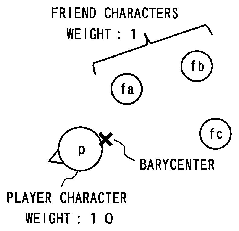
Then, the CPU202obtains weights of the characters placed in the game space (S304). The weights of the characters, which are previously decided and stored in the DVD-ROM30, are read from the DVD-ROM30, and stored in the main memory214as shown inFIG. 6. Thus, the CPU202can read these data from the main memory214in step S304. In the example shown inFIG. 6, the weight of the player character is set to 10, the weights of the friend characters fa, fb, fc, . . . are set to 1, and the weights of the enemy characters ea, eb, ec, . . . are set to 3.
Note that the DVD-ROM30does not necessarily need to store the weights of the characters. For example, if data indicating levels of importance (A, B, C) of the characters are stored in the DVD-ROM30as shown inFIG. 7, the weight of each character may be obtained in step S304as follows: the level of importance of each character is first obtained, and the level of importance of the character is converted to a weight using a conversion table as shown inFIG. 8, for example.
Next, based on the positions of the characters, which are obtained in step S302, and the weights of the characters, which are obtained in step S304, the CPU202calculates a barycenter of the characters (S306). The above calculation is performed as follows, for example.
Let us assume that the player character, the friend characters fa and fb, and the enemy character ea are placed in the game space. In this case, coordinates (Xb, Yb, Zb) of the barycenter are calculated as follows.
“X-coordinate of the barycenter”={(“x-coordinate of the player character”דweight of the player character”)+(“x-coordinate of the friend character fa”דweight of the friend character fa”)+(“x-coordinate of the friend character fb”דweight of the friend character fb”)+(“x-coordinate of the enemy character ea”דweight of the enemy character ea”)}/(“weight of the player character”+“weight of the friend character fa”+“weight of the friend character fb”+“weight of the enemy character ea”). That is, the x-coordinate of the barycenter is calculated by the following equation:
Xb={(Xp×10)+(Xfa×1)+(Xfb×1)+(Xea×3)}/(10+1+1+3)
As is the case with the x-coordinate, the y- and z-coordinates of the barycenter are calculated, respectively, as follows:
Yb={(Yp×10)+(Yfa×1)+(Yfb×1)+(Yea×3)}/(10+1+1+3)
Zb={(Zp×10)+(Zfa×1)+(Zfb×1)+(Zea×3)}/(10+1+1+3)
As such, in step S306, the barycenter is calculated by averaging the characters' coordinate values with values weighted by the characters' weights.
In a following step S308, the CPU202sets the sight point of the virtual camera to the barycenter calculated in step S306, and ends the virtual camera position updating process. As shown inFIG. 9, an orientation of the virtual camera is determined in accordance with the sight point. That is, as shown inFIG. 10, the sight point lies in a center of the image generated by using the virtual camera. As described above, the sight point of the virtual camera is set to the barycenter in step S308. Thus, the barycenter calculated in step S306lies in a center of the image generated in step S116ofFIG. 3.
Hereinafter, the embodiment will be described in further detail using a more specific example.
As shown inFIG. 11, for example, in the case where the player character leads a party of three friend characters fa to fc in the game space, the barycenter lies near the player character, whereby an image as shown inFIG. 12, whose center coincides with the barycenter, is generated.
Also, as shown inFIG. 13, for example, in the case where friend characters fd to fi are added to the party shown inFIG. 11, the barycenter comes closer to a center of the party compared toFIG. 11(see an arrow inFIG. 13). As a result, as shown inFIG. 14, the player character and the friend characters are displayed in a balanced manner. If the barycenter remained in the position as shown inFIG. 11, the friend characters fe, fi, and fj would not be displayed on the screen.
In the case where the position of the barycenter changes from the position as shown inFIG. 11to the position as shown inFIG. 13, the sight point of the virtual camera has to be changed accordingly. In this case, the virtual camera may be moved parallel to a moving direction of the barycenter as shown inFIG. 15, only the orientation of the virtual camera may be changed as shown inFIG. 16, or other arbitrary methods may be used. In this case, it is preferable to adjust the sight point to the barycenter by bringing the sight point closer to the barycenter at a constant rate (corresponding to 30 percent of a distance between the sight point and the barycenter, for example) or at a constant speed, rather than immediately setting the sight point to the barycenter. As a result, even if the position of the barycenter substantially changes due to a sudden emergence of a heavy character, for example, a display area does not drastically change, and the center of the screen comes gradually closer to the emerged character. Thus, it is possible to always display an easily viewable screen.
Furthermore, as shown inFIG. 17, in the case where there are four friend characters behind the player character, and two enemy characters ahead of the player character, the barycenter lies ahead of the player character, even as the friend characters outnumber the enemy characters, due to a weight difference. As a result, both of the enemy characters are displayed as shown inFIG. 18, and the player character can fight with the enemy characters ea and eb while viewing their movements. As such, setting is previously performed so that an object to be displayed preferentially has a heavier weight than other characters, whereby it is possible to arbitrarily control priority based on which of the characters are displayed.
If the player character operated by the player moves outside the display area, the player has difficulty in operating the player character. Thus, it is preferable to assign the heaviest weight to the player character so that it is always displayed on the screen. However, if there are a great number of other characters, the barycenter moves away from the player character and comes closer to other characters, even if the heaviest weight is assigned to the player character. In order to avoid such a problem, the weight of the player character may be determined dynamically. For example, if the sum of the weights of the characters other than the player character is dynamically assigned to the player character as its weight, the weight of the player character is 10 inFIG. 19, and the weight thereof is 27 inFIG. 20. Thus, even if the number of other characters is substantially increased, the barycenter does not so much move away from the player character. In order to realize the above-described process, the weights of the characters other than the player character are obtained based on each character's weight obtained in step S304ofFIG. 5, for example, and the sum of the weights can be used as the weight of the player character in a barycenter calculating process in step S306.
The present embodiment can be easily applied to a case of displaying a scene viewed from a player character's viewpoint. In this case, as shown inFIG. 21, a barycenter is determined based on a character other than the player character. As a result, as shown inFIG. 22, an image viewed from a first person viewpoint is generated such that a barycenter lies in a center thereof.
As shown inFIG. 23, a weight of a character outside a predetermined area may be ignored (that is, a barycenter calculating process is not performed for the above weight; in other words, the above weight is assumed to be zero). For example, in the case where some other characters are located far away from the player character in the game space, the barycenter is set in an unexpected position due to an influence of these characters. Therefore, as shown inFIG. 23, only a weight of a character within a reasonably limited area is taken into consideration, whereby it is possible to avoid the above-described problem. In order to realize the above process, a process for extracting characters located within a predetermined area is added as a previous stage of step S302ofFIG. 5, for example, and a barycenter calculating process in steps S302to S306is performed for the extracted character. By this additional process, a calculating process for characters outside the predetermined area can be omitted.
InFIG. 23, it is assumed that a predetermined area is a closed area whose outer edge is at a predetermined distance from the player character, but it is not limited thereto. The predetermined area may be arbitrarily set. For example, the predetermined area may be a rectangular area whose center is at a predetermined distance from a front of the player character, or may be a closed area whose outer edge is at a predetermined distance from the sight point.
In order to ensure that the player character is always displayed, as shown inFIG. 24, a sight point may be limited within a predetermined allowable limit which is centered around the player character. For example, as shown inFIG. 24, in the case where a barycenter lies outside the allowable limit, an intersection point of a line segment connecting the barycenter and the player character and an outer edge of the allowable limit is set as a sight point. In order to realize the above-described process, for example, a process performed in step S308ofFIG. 5may be replaced with a process in which determination is made whether or not the barycenter lies within the allowable limit. If the determination is made that the barycenter lies within the allowable limit, a sight point is set to a position of the barycenter. On the other hand, if the determination is made that the barycenter lies outside the allowable limit, a sight point is set to an intersection point of a line segment connecting the barycenter and the player character and an outer edge of the allowable limit.
In the case where a distance between the virtual camera and the sight point changes, it is preferable that the weight of the player character changes in accordance with the above distance. Hereinafter, the above-described case will be described with reference toFIGS. 25 to 28.
Here, as shown inFIG. 25, a case in which the virtual camera can be placed in one of three relative positions (first to third positions) based on the sight point will be described. In this case, the weight of the player character is set in accordance of a position of the virtual camera. As shown inFIG. 26, the closer the distance between the sight point and the virtual camera becomes, the heavier the player character becomes. In place of preparing a table as shown inFIG. 26, the weight of the player character may be calculated using the distance between the sight point and the virtual camera as an argument.
FIG. 27is an illustration showing a position of a barycenter in the case where the virtual camera is placed in a first position, and a display area whose center corresponds to the barycenter. If the virtual camera changes its position from the first position to the third position whereas the player character maintains the same weight (that is, 10), the player character is pushed off the display area because the image is zoomed in on using the barycenter as shown inFIG. 27as a center point. However, if the weight of the player character changes from 10 to 50 when the position of the virtual camera changes from the first position to the third position, the barycenter comes closer to the player character as shown inFIG. 28, whereby the player character is reliably displayed.
In order to realize the above-described process, the main memory214stores the table as shown inFIG. 26by reading the table from the DVD-ROM30, for example, and determination is made on whether the virtual camera is placed in the first, second or third position when the weight of each character is obtained in step S304ofFIG. 5. Based on the above determination, the weight of the player character can be obtained by referring to the table ofFIG. 26.
Note that, in one illustrative embodiment, a case of displaying the characters placed in the three-dimensional game space has been described. The same can be easily applied to a case of displaying the characters placed in a two-dimensional game space. In this case, a barycenter is calculated based on the position and the weight of each character, and an image in which the calculated barycenter lies in approximately the center thereof is generated.
Also, in one illustrative embodiment, a case of displaying the player character, the friend character, and the enemy character, which are placed in the game space, has been described. However, it is also possible to display other objects in a similar manner. For example, it is possible to assign a weight to a stationary object such as a tree.
While the example embodiment presented herein has been described in detail, the foregoing description is in all aspects illustrative and not restrictive. It is understood that numerous other modifications and variations can be devised without departing from the scope of the example embodiment.
Claims
- A storage medium for storing an image generating program which causes a computer to generate a display image used for displaying a plurality of objects placed in a two-dimensional or three-dimensional virtual space, wherein the image generating program causes the computer to perform: storing weighted values of the objects;storing positions of the objects in the virtual space;determining a barycenter of the objects based on the weighted values and the positions of the objects;and generating a display image in which the barycenter lies in approximately a center of the display image, wherein a heaviest weighted value is assigned to a player character which is operable by a player, and wherein a weighted value equal to or greater than a sum of weighted values of objects other than the player character is dynamically assigned to the player character.
- The storage medium according to claim 1 , wherein the player character, as one of the objects, is displayed preferentially by virtue of having assigned to it the heavier weighted value than other objects.
- The storage medium according to claim 1 , wherein a level of importance is previously provided for each object, and the image generating program further causes the computer to perform assigning a heavier weighted value to the player character, as one of the objects, for which a higher level of importance is provided compared to other objects.
- The storage medium according to claim 1 , wherein, in the determining a barycenter, the image generating program causes the computer to determine a barycenter of objects placed within a predetermined area, which is a portion of the virtual space.
- The storage medium according to claim 1 , wherein, if a barycenter determined by the determining a barycenter lies outside a predetermined allowable limit which is centered around specific one object of the plurality of objects, the image generating program causes the computer, in the generating a display image, to generate a display image in which an intersection point of a line segment, connecting the barycenter and the specific one object, and an outer edge of the allowable limit lies in approximately a center of the display image.
- The storage medium according to claim 1 , wherein, the virtual space is a three-dimensional virtual space, and the display image generating further includes generating a display image using a virtual camera whose sight point is the barycenter.
- The storage medium according to claim 6 , wherein a weighted value of a specific one object of the plurality of objects changes in accordance with a position of the virtual camera.
- The storage medium according to claim 7 , wherein the closer a distance between the virtual camera and the sight point becomes, the heavier a weighted value of the specific one object becomes.
- The storage medium according to claim 1 , wherein the virtual space is a three-dimensional space, and the generating a display image further includes generating a display image by bringing the sight point of a virtual camera closer to the barycenter determined by the determining a barycenter at a constant rate.
- A game device for generating a display image used for displaying a plurality of objects placed in a two-dimensional or three-dimensional virtual space, comprising: weight storage locations for storing weighted values of the objects;position storage locations for storing positions of the objects in the virtual space;barycenter determination programmed logic circuitry for determining a barycenter of the objects based on the weighted values and the positions of the objects;and display image generating programmed logic circuitry for generating a display image in which the barycenter lies in approximately a center of the display image, wherein a heaviest weighted value is assigned to a player character which is operable by a player, and wherein a weighted value equal to or greater than a sum of weighted values of objects other than the player character is dynamically assigned to the player character.
- A method of displaying a virtual environment containing a plurality of virtual objects comprising: storing a weighted value for at least two of the virtual objects;storing a position value for the at least two virtual objects;determining an average position between the at least two virtual objects based at least in part on the stored weighted values and positions for each of the at least two virtual objects;and displaying a virtual environment wherein a displayed center of the displayed environment depends at least in part on the position determined by the determining an average position, wherein a heaviest weighted value is assigned to a player character which is operable by a player, and wherein a weighted value equal to or greater than a sum of weighted values of objects other than the player character is dynamically assigned to the player character.
- The method of claim 11 , wherein the virtual environment is a two-dimensional environment.
- The method of claim 11 , wherein the virtual environment is a three-dimensional environment and the displaying a virtual environment further includes displaying a virtual environment wherein the sight point of a virtual camera is the displayed center.
Disclaimer: Data collected from the USPTO and may be malformed, incomplete, and/or otherwise inaccurate.