U.S. Pat. No. 7,682,250
METHOD AND APPARATUS FOR SIMULATING INTERACTIVE SPINNING BAR GYMNASTICS ON A 3D DISPLAY
AssigneeNintendo Co., Ltd.
Issue DateAugust 14, 2006
U.S. Patent No. 7,682,250: Method and apparatus for simulating interactive spinning bar gymnastics on a 3D display

Summary:
The ‘250 patent describes a 3Dhand-held game where the user can use a stylus to control his character and have the character perform gymnastic actions during gameplay. The invention allows a player to instruct his character to grab onto an elongated metal bar. Once the character is attached, the player may use the stylus to have his character perform gymnastic moves on the bar. These types of moves include handstands, spinning around the bar, and a variety of dismounts. A player may tap the screen while his character is spinning on the bar to activate a dismount sequence whereby the character lets go of the bar and flies in the air.
Abstract:
The video or other computer graphics display shows, on a touch screen, a spinnable bar having a control wheel affixed to an end thereof. Strokes of a stylus applied to the surface of the wheel controls the direction and/or rate of spin of the wheel and bar. An animated game character holding on to the spinning bar may spin with the bar and perform acrobatic acts in response to other touch screen or other types of control inputs.
Illustrative Claim:
1. A method for modeling a gymnastic exercise comprising: displaying an animated game character holding on to an elongated object, the animated game character being moveable independently of said elongated object; detecting user manipulation of a control input device; determining, in response to said detected user manipulation, whether said user in manipulating said control input device has supplied a gesture simulating touch imparting a push to said elongated object; using animation to cause said displayed elongated object to appear to spin with an angular momentum so that repeated gestures simulating pushes in the direction of spin increase the apparent rate said virtual object spins; using animation to make the displayed elongated object appear to impart spin to said independently-movable animated game character so that said animated game character appears to spin with the spinning elongated object; and changing the rate of the spin of said elongated object in response at least in part to the detected control input.
Illustrative Figure
Abstract
The video or other computer graphics display shows, on a touch screen, a spinnable bar having a control wheel affixed to an end thereof. Strokes of a stylus applied to the surface of the wheel controls the direction and/or rate of spin of the wheel and bar. An animated game character holding on to the spinning bar may spin with the bar and perform acrobatic acts in response to other touch screen or other types of control inputs.
Description
DETAILED DESCRIPTION Exemplary Video Game Platform InFIG. 1A, an exemplary illustrative non-limiting game apparatus1includes two liquid crystal displays (LCDs)11and12, which are accommodated in a housing18so as to be located at predetermined positions. Specifically, in the case where the first liquid crystal display (hereinafter, referred to as the “LCD”)11and the second LCD12are accommodated in a vertically stacking manner, the housing18includes a lower housing18aand an upper housing18b. The upper housing18bis pivotably supported by a part of an upper surface of the lower housing18a. The upper housing18bhas a planar shape slightly larger than a planar shape of the first LCD11, and has an opening for exposing a display screen of the first LCD11on one main surface thereof. The lower housing18ahas a planar shape longer in the horizontal direction than the planar shape of the upper housing18b, and has an opening for exposing a display screen of the second LCD12at approximately the center of the lower housing18bin the horizontal direction. One of two side sections of the lower housing18ainterposing the second LCD12has speaker holes of a speaker15, and each of the two side sections has an operation switch section14. The operation switch section14includes an operation switch (button A)14aand an operation switch (button)14bwhich are attached to one main surface of the side section of the lower housing18awhich is to the right of the second LCD12as seen inFIG. 1. The operation switch section14also includes a direction indication switch (cross key)14c, a start switch14d, and a select switch14ewhich are attached to one main surface of the side section of the lower housing18ato the left of the second LCD12as seen inFIG. 1. The lower housing18afurther includes side surface switches14fand14g, which are respectively provided on the upper surfaces of the side sections of the lower housing18ato the left and to the right of the second LCD12. When necessary, further ...
DETAILED DESCRIPTION
Exemplary Video Game Platform
InFIG. 1A, an exemplary illustrative non-limiting game apparatus1includes two liquid crystal displays (LCDs)11and12, which are accommodated in a housing18so as to be located at predetermined positions. Specifically, in the case where the first liquid crystal display (hereinafter, referred to as the “LCD”)11and the second LCD12are accommodated in a vertically stacking manner, the housing18includes a lower housing18aand an upper housing18b. The upper housing18bis pivotably supported by a part of an upper surface of the lower housing18a. The upper housing18bhas a planar shape slightly larger than a planar shape of the first LCD11, and has an opening for exposing a display screen of the first LCD11on one main surface thereof. The lower housing18ahas a planar shape longer in the horizontal direction than the planar shape of the upper housing18b, and has an opening for exposing a display screen of the second LCD12at approximately the center of the lower housing18bin the horizontal direction. One of two side sections of the lower housing18ainterposing the second LCD12has speaker holes of a speaker15, and each of the two side sections has an operation switch section14.
The operation switch section14includes an operation switch (button A)14aand an operation switch (button)14bwhich are attached to one main surface of the side section of the lower housing18awhich is to the right of the second LCD12as seen inFIG. 1. The operation switch section14also includes a direction indication switch (cross key)14c, a start switch14d, and a select switch14ewhich are attached to one main surface of the side section of the lower housing18ato the left of the second LCD12as seen inFIG. 1. The lower housing18afurther includes side surface switches14fand14g, which are respectively provided on the upper surfaces of the side sections of the lower housing18ato the left and to the right of the second LCD12. When necessary, further operation switches may be provided, or unnecessary operation switches may be removed.
On an upper surface (the surface entirely shown inFIG. 1) of the second LCD12, a touch panel13(surrounded by the dashed line inFIG. 1) is provided. The touch panel13is of, for example, any of a resistance film system, an optical (infrared) system, and a static capacitance coupling system. When a stylus16(or a finger) presses, moves on, or touches an upper surface of the touch panel13, the coordinate position of the stylus16is detected and the coordinate data is output.
In the vicinity of a side surface of the upper housing18b, an accommodation hole (an area represented by the two-dot chain line inFIG. 1) is formed when necessary for accommodating the stylus16for operating the touch panel13. In a part of one surface of the lower housing18a, a cartridge insertion section (an area represented by the one-dot chain line inFIG. 1) is formed, for detachably accepting a game cartridge17(hereinafter, referred to simply as the “cartridge17”) having a built-in memory (e.g., a ROM) which stores a game program. The cartridge17is a memory medium storing a game program, and is, for example, a nonvolatile semiconductor memory such as a ROM or a flash memory. A part of the lower housing18binner to the cartridge insertion section has a built-in connecter (seeFIG. 2) to be electrically connected with the cartridge17. The lower housing18a(or the upper housing18b) accommodates an electronic circuit board having various electronic components such as a CPU and the like mounted thereon. The memory medium for storing the game program is not limited to the nonvolatile semiconductor memory, but may be a CD-ROM, a DVD, or a similar optical disc-shaped memory medium.
Next, with reference toFIG. 1B, an internal structure of the game apparatus1will be described.FIG. 1Bis a block diagram showing the internal structure of the game apparatus1.
InFIG. 1B, an electronic circuit board accommodated in the housing18has a CPU core21mounted thereon. The CPU core21is connected to the connector28, to be connected to the cartridge17, via a predetermined bus, and the CPU core21is also connected to an input/output interface (I/F) circuit27, a first graphic processing unit (first GPU)24, a second graphic processing unit (second GPU)26, and a working RAM (WRAM)22.
To the connecter28, the cartridge17is detachably connectable. As described above, the cartridge17is a memory medium for storing a game program. Specifically, the cartridge17has a ROM171storing the game program and a RAM172rewritably storing backup data mounted thereon. The game program stored in the ROM171in the cartridge17is loaded on the WRAM22, and the game program loaded on the WRAM22is executed by the CPU core21. Temporary data and data for generating an image which are obtained by the CPU core21through execution of the game program are stored in the WRAM22.
As described above, the ROM171stores a game program, which is a group of instructions and a group of data in the format executable by the computer of the game apparatus1, especially by the CPU core21. The game program is read into and executed by the WRAM22when necessary. In this embodiment, the game program and the like are recorded in the cartridge17, but the game program and the like may be supplied by another medium or via a communication network.
The I/F circuit27is connected to the touch panel13, the operation switch section14, and the speaker15. The speaker15is located at a position just inside the speaker holes described above.
The first GPU24is connected to a first video RAM (hereinafter, referred to the “VRAM”)23, and the second GPU26is connected to a second VRAM25. In accordance with an instruction from the CPU core21, the first GPU24generates a first game image based on data for generating an image stored in the WRAM22and draws the first game image in the first VRAM23. In accordance with an instruction from the CPU core21, the second GPU26generates a second game image based on data for generating an image stored in the WRAM22and draws the second game image in the second VRAM25.
The first GPU24is connected to the first LCD11, and the second GPU26is connected to the second LCD12. In accordance with an instruction from the CPU core21, the first GPU24outputs the first game image drawn in the first VRAM23to the first LCD11. The first LCD11displays the first game image which is output from the first GPU24. In accordance with an instruction from the CPU core21, the second GPU26outputs the second game image drawn in the second VRAM25to the second LCD12. The second LCD12displays the second game image which is output from the second GPU26.
The I/F circuit is a circuit for exchanging data between external input/output devices such as the touch panel13, the operation switch section14, the speaker15and the like, and the CPU core21. The touch panel13(including a device driver for the touch panel13) has a coordinate system corresponding to a coordinate system of the second VRAM25, and outputs coordinate position data corresponding to the position which is input (indicated) by the stick16or the like. The resolution of the display screen of the second LCD12is, for example, 256 dots×192 dots, and the detection precision of the touch panel13is 256 dots×192 dots in correspondence with the resolution of the display screen of the second LCD12. The precision detection of the touch panel13may be lower or higher than the resolution of the display screen of the second LCD12.
Exemplary Character Rotation and Movement
According to one exemplary non-limiting illustrative embodiment shown inFIG. 2A, videogame software stored on memory card28or otherwise provided to videogame system10(e.g., via a wireless download) controls system10to display a game character101(e.g., a gymnast) grasping a bar129.
In one exemplary illustrative non-limiting implementation, bar127may model a competition high bar of the type used by gymnasts throughout the world. Such “high bar” equipment may comprise for example a stainless steel bar mounted using a double cable tensioning system at a sufficient height above the floor to provide sufficient room for acrobatic moves. In some exemplary illustrative non-limiting implementations, the bar127need not exactly model a real world high bar, but may instead model unusual “spinning” bar equipment where the bar127is rotatable mounted on supports so that it spins and is capable of causing a game character holding on to it to spin along with it. In this example implementation, the bar129can spin relative to a 3D world. Meanwhile, game character101can spin with bar129. The bar129thus, in the exemplary illustrative non-limiting implementation, only roughly models a real gymnastic high bar on which a gymnast can perform feats of gymnastic skill. In other exemplary illustrative non-limiting implementations, however, the modeling can be made more accurate to a real world high bar or other piece of gymnastic or other equipment.
The exemplary illustrative non-limiting implementation simulates a physically rotatable horizontally oriented bar129having fixed thereto a wheel127that the game player can manipulate to control the spin of the bar. By touching the area of touch-sensitive display22immediately over the depiction of wheel127with a vertical upward or downward stroke, the game player can cause the bar to rotate in a clockwise or counterclockwise direction. An upwardly-directed stroke may for example cause the bar to rotate in a clockwise direction (as one looks at the wheel axially), and a downward stroke directed to the wheel may cause the bar to rotate in a counterclockwise (with reference to an axial end view of the wheel). In the exemplary illustrative non-limiting implementation, the touch screen22cannot detect force but only touch, so that the exemplary illustrative non-limiting implementation uses repetitive strokes to allow the game player to apply rotational force to the spin of wheel127and thus to the bar. The more strokes the game player applies to wheel127in the same direction, the faster the wheel and associated bar spins. If the player applies a stroke in a different direction from the direction which the bar is currently spinning, the result can be a decrease in the rate of spin. If the game player leaves the wheel alone for a while and does not apply any stroke, the wheel127and associated bar may eventually and gradually decrease its rate of spin and finally come to rest. The rate at which the wheel and bar decrease their spin may be programmed to model a desired mass, angular momentum, friction factor and other physical factors. The appearance of the spinning wheel127may be textured to provide a perception that the game player is actually engaging a rough circumferential surface of the wheel127with stylus24.
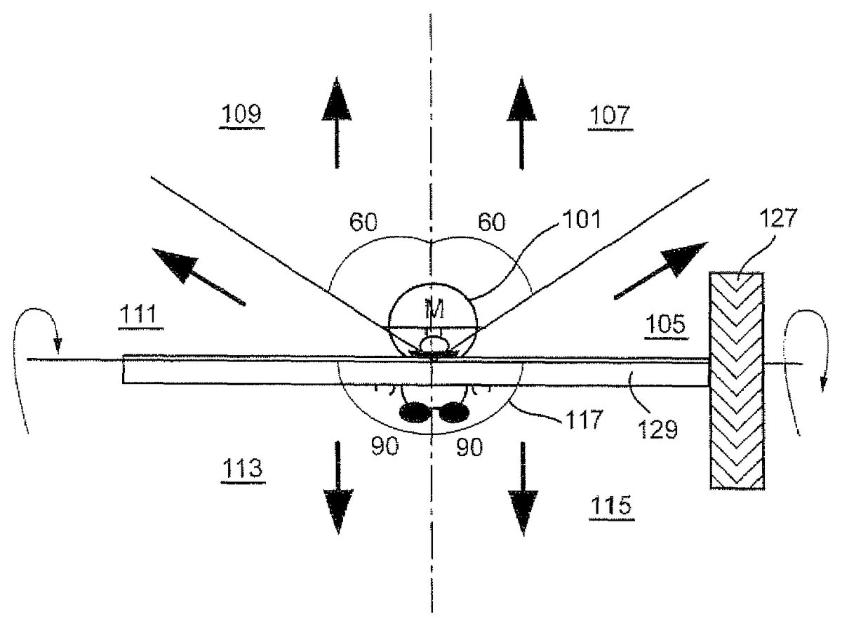
As shown inFIGS. 2A-2C, once the game player has used stylus24to start the wheel127and associated bar spinning, he or she may use the same stylus to cause a game character to do acrobatics from the bar such as for example to leap from the spinning bar and catch it again, to leap off of the spinning bar or the like. In the example scenario shown inFIG. 2A, if the player wishes to move the game character101away from the bar129, the player indicates a direction in which he wishes the character to move. If the game character is displayed on touch-screen22, for example, the player can indicate a direction in which the character is to move using stylus24. The player can place stylus24in a selection zone to indicate that the player has selected the game character for movement and a particular direction in which to move. Gestures may also be used to direct particular moves (e.g., mount, dismount, giant, etc.).
An exemplary selection zone is shown inFIG. 2B. According to the example inFIG. 2B, the center115of the zone is centered at the center of the game character101. Some degree of allowance117may also be provided around the zone so that the player does not have to indicate a single point115exactly with the stylus. As long as the player places the tip of the stylus within the area of allowance117, the game will know that the player wishes to select the character for control. In the particular illustrative example shown, the tolerance is six pixels, although this amount can be varied with the desired degree of difficulty in player selection. For example, if the developer wishes that the player should make very precise movements for a difficult part of the game, this area117may be decreased accordingly. In the exemplary illustrative non-limiting implementation, the allowance is larger when the bar is spinning than when it is not spinning. For example, in one exemplary illustrative non-limiting implementation, the allowance may be set to a value such as 4 pixels in any direction when the character is not spinning, standing, idling, walking or the like. However, as soon as the character begins to spin, the allowance may be increased to a larger value (e.g., 6 pixels each way). These values are just examples—any number can be chosen by the designer. By providing an increased allowance when the character is spinning, it becomes easier for the game player to control a rapidly moving or animated game player.
According to this exemplary illustrative non-limiting implementation, once the player has selected the game character for movement, the player may then indicate a direction in which the game character is to be moved and possibly also the type of movement desired. In the exemplary movement zones shown inFIG. 2A, there are six possible movement zones with four possible movement directions. If, after selecting the character, the player moves the stylus through zones107or109the character may jump upwards from the bar. The height of this jump may be affected by how fast the bar is currently spinning. If the player moves the stylus through zones105or111, the character may jump right or left respectively. If the player wishes the character to dismount, he can move the stylus through zones103or113. The speed the bar is rotating can affect the speed at which the character leaves the bar. If the game character has to, for example, smash into a block hard enough before the block gives way, allowing passage to a new section of the game, the player may cause the character to achieve some level of speed on the bar and then instruct the character to dismount forcefully. In the example shown inFIG. 2A, by way of non-limiting example only, regions107and109are 60 degrees,105and111are 30 degrees, and103and113are 90 degrees. This can vary with both the number of regions and the desire of the developer to make motion in a particular direction difficult. If the challenge of a portion of the game is a precise jump, then a region of only a few degrees in the appropriate direction may be provided.
In the exemplary non-limiting illustrative implementation shown inFIGS. 3A,3B and3C, the player instructs a bar129displayed in the game space to spin, by manipulating a wheel127also displayed in the game space, with stylus24. Although the axis of the wheel127is aligned with the axis of the bar129in this example, the wheel or bar could also be displayed from other perspectives, and their axes connected by gears or an unseen connection.
FIG. 3Ashows an exemplary representation of a player interacting with the wheel127in order to cause the bar to spin. The dark arrow121represents the current position of the stylus, while the light arrows123represent previous stylus positions. The stylus121is translated in a downward motion125with the tip touching the wheel127. If the wheel were displayed perpendicularly to the bar, then the player may move stylus24in a circular motion. The player's motion causes the wheel127to begin to rotate in the same direction125as the motion, which in turn causes the bar129, and the game character101grasping the bar, to rotate131about the bar's axis. The bar may simply have a single speed, or the developer may wish the player's repeated strokes to increase or decrease bar speed. As one example, the bar may have four speeds. Every fourth stroke of the player may move the bar up to the next speed level. Additionally, if the player is idle for a certain period of time, say forty updates, where an update is when the game checks for input, the bar may move down a speed level, simulating the effects of friction and gravity.
According to this example of this implementation, if the bar is in state 0 of the index, then the bar is at its slowest motion speed. As the bar state moves up or down in speed state, the rate at which the bar is spinning will accelerate or decelerate respectively. Additionally, when the bar moves from a motionless state to state 0, the animation may process on the next update, when the bar moves to state 1, the animation may process immediately, without waiting for the next update. In the same fashion, when the bar moves to state 2, the animation will again wait for the next update, and the switch to state 3 will process immediately. This can create a sense of acceleration and deceleration with a few simple frames of flip-book like animation.
This implementation also allows the speed of the player's strokes to affect the speed at which the bar accelerates or decelerates. If the strokes are input and processed rapidly, then the player appears to have quickly spun the bar through a series of rapid hand movements. If the strokes are input slowly, however, the bar takes longer to get to a maximum speed due to the slower input of spin instructions.
FIG. 3Bis an exemplary representation of the selection of a character101which has been rotated through manipulation of the wheel. Once the desired spin speed has been reached, the player moves the stylus121from a former position123, where the tip was touching the wheel, to a new position121, where the tip is within the selection region of the game character101. Using the stylus, the player can now indicate a direction or other action in which he desires the game character to move. An aspect of skill can be added here, especially if the bar slows down quickly, for the player must then quickly cease manipulation of the wheel to spin the bar and rapidly select and instruct character movement.
FIG. 3Cis an exemplary representation of the game character101moving in a direction133indicated by the player. The player, after having positioned the stylus at a point123where the tip was within the selection zone of the game character101, translates the stylus121towards the top of the screen, moving it to a new position121. The game character101moves in the direction indicated by the stylus121, and its speed and height achieved may depend on the speed at which the bar was spinning when the character let go or otherwise became decoupled from the bar.
FIGS. 4A-4Care flowcharts of exemplary illustrative non-limiting program control steps performed by CPU core42in conjunction with GPU's50,52and other components to provide the display effects described above. Referring toFIG. 4A, CPU core42initializes a stroke counter to a predetermined initial value (e.g., 0) (block1002) and then displays the bar in character as shown inFIG. 3A(block1004). The CPU core42may then, via interface circuit54, detect inputs from touch panel22and operating switch20(block1006) and update the stroke counter in accordance with such inputs (block1008). CPU core42in conjunction with GPU's50,52may then update the displays12,14(block1010) and repeat the steps described above.
FIG. 4Bshows an example illustrative non-limiting implementation of the update stroke counter routine if block1008. In this particular illustrative exemplary non-limiting implementation, there are a total of four degrees of speed for the spinning wheel127. In one exemplary illustrative non-limiting implementation, it take a predetermined number of strokes by stylus24(e.g., 4 strokes) to increase by a degree of speed. In one exemplary illustrative non-limiting implementation, a certain predetermined total number of strokes of stylus24(e.g., 16 strokes) will cause the wheel127to spin at a top speed. In the exemplary illustrative non-limiting implementation, if a stroke is detected (decision block1012), then CPU core42increments the stroke counter (block1014). If there has been no stroke or other control input for certain number of update, loop or polling periods (e.g., 40 updates) (decision block1016), the stroke counter is decreased (e.g., by 1)—modeling artificial friction that causes the wheel127to slow down and eventually to stop (block1018). This exemplary illustrative non-limiting scheme creates a sense of acceleration and deceleration with just a few frames of a simple flipbook animation.
FIG. 4Cshows an exemplary illustrative non-limiting implementation of an “update display” routine1010. In this example, the stroke counter value is translated into a rotation index using an array (block1020). In a particular example shown, incrementing the stroke counter by one causes the stroke counter to index to the next successive entry in the array. Once the stroke counter has been incremented to a maximum value in the illustrative exemplary non-limiting implementation, it is incremented no further and remains at that maximum even in response to further stroke inputs. In this particular example, the first to fourth strokes will return rotation index 0, the fifth to eighth strokes will return rotation index 1, and so one. In the exemplary illustrative non-limiting implementation, the rotation index not only represents the rotational speed, but also is used to update the animation accordingly. For example, in this exemplary illustrative non-limiting implementation:rotation index 0: on next update, the wheel switches to next frame of animationrotation index 1: the wheel switches to next frame of animation immediatelyrotation index 2: on next update, the wheel goes to the next of next frame of animation (i.e., it skips a frame and progresses to a second subsequent frame)rotation index 3: the wheel goes to the next of next frame of animation immediately (e.g., it immediately progresses to a second subsequent frame without waiting for an update).
The above operations are represented schematically byFIG. 4Cblocks1022-1024. In this particular exemplary illustrative non-limiting implementation, if the rotation index is 1 or 3 (“yes” exit to decision block1022), CPU core42switches the wheel to a subsequent animation frame immediately—with a rotation index of 1 switching to a next successive animation frame; and a rotation index of 3 switching to a second subsequent animation frame (thereby skipping a frame) (block1023). If the rotation index is 0 or 2 (“no” exit to decision block1022), then CPU core42will wait until the next update to switch the wheel to a subsequent animation frame (block1024)—with a rotation index of 0 switching to a next frame and a rotation index of 2 switching to a second subsequent frame (thereby skipping an intermediate frame).
If desired, the array shown in block1020can be expanded to include a “stop” (F) entry to indicate when the wheel127has stopped rotating such that the wheel display animation should not be updated but should remain the same. Alternatively, a different mechanism could be used to suppress the “update display” routine1010from operating when the stroke counter has decremented to a minimum value such that the rotating wheel127is at a complete standstill and is not rotating at all. In some exemplary illustrative non-limiting implementations, it may be desirable to have the rotating wheel rotate at least slowly at all times. In other exemplary illustrative non-limiting implementations, the friction of bearings and other contact surfaces may be modeled by allowing the wheel to eventually slow down to a complete stop if the user has not applied a stroke to keep the wheel moving for awhile.
The described implementations give the player a feeling of direct control over various aspects of in-game events. The player, through the speed of his motions, can affect the speed at which the character spins. Also, the player's motions can directly translate into the motions of a wheel and a bar, allowing the player to feel as if he has directly manipulated the virtual objects. The player can pick the precise moment at which to cause the character to leap from the bar, and can control that leap directly, enhancing the player's feeling of control. Any of these direct control aspects can be changed or limited by the developer in accordance with the particular game to be played, and additional direct control aspects, as previously noted, can be provided.
Although the exemplary illustrative non-limiting implementations described above make use of the stylus24and touch screen22, alternative implementations using other types of control inputs (e.g., joysticks, pointing devices, push buttons, voice control or any other convenient inputs) may be provided. While rotation in the exemplary illustrative non-limiting implementations described above model a spinning bar with a wheel fixed to its end, other geometries are possible. Any elongated or other type of object may be caused to spin. Examples include a bicycle wheel, a satellite in space, a top, an airplane propeller or any other rotational object in the real or imaginary world. While the exemplary illustrative non-limiting implementation described above permits rotation in either direction (clockwise or counterclockwise), other exemplary illustrative non-limiting implementation might only provide rotation in a single direction. While the exemplary illustrative non-limiting implementation described above fixes the other degrees of freedom of the spinning bar beyond rotation, other implementations can allow the user to control the orientation and any or all of the other five degrees of freedom.
While the technology herein has been described in connection with exemplary illustrative non-limiting implementations, the invention is not to be limited by the disclosure. The invention is intended to be defined by the claims and to cover all corresponding and equivalent arrangements whether or not specifically disclosed herein.
Claims
- A method for modeling a gymnastic exercise comprising: displaying an animated game character holding on to an elongated object, the animated game character being moveable independently of said elongated object;detecting user manipulation of a control input device;determining, in response to said detected user manipulation, whether said user in manipulating said control input device has supplied a gesture simulating touch imparting a push to said elongated object;using animation to cause said displayed elongated object to appear to spin with an angular momentum so that repeated gestures simulating pushes in the direction of spin increase the apparent rate said virtual object spins;using animation to make the displayed elongated object appear to impart spin to said independently-movable animated game character so that said animated game character appears to spin with the spinning elongated object;and changing the rate of the spin of said elongated object in response at least in part to the detected control input.
- The method as in claim 1 further including skipping animation frames to impart the appearance of a more rapid spin in response to at least a predetermined number of control inputs occurring within a certain time period.
- The method as in claim 2 further including calculating a rotation index in response to a stroke count, and using the rotation index to determine when to switch to a next animation frame.
- The method as in claim 1 including calculating a rotation index based at least in part on a stroke count.
- The method as in claim 1 wherein said detecting includes detecting stroke inputs on a touch screen.
- . The method of claim 1 , further including moving the independently movable animated game character in response to user manipulation of a control input device.
- A method of simulating gymnastic exercise comprising: displaying, on a 3D computer graphics display, a representation of an elongated object having first and second ends and a wheel affixed axially to said first end thereof;detecting touch screen stroke inputs to determine whether said touch screen stroke inputs comprise a gesture imparting spin to said wheel and, in response thereto, imparting spin at a controlled rate to said wheel and the affixed elongated object with an angular momentum so that repeated gestures in the direction of spin increase the apparent rate said elongated object spins;animating, on said display, an avatar holding on to said elongated object, said avatar being movable independently of said elongated object but also capable of simulating holding said elongated object to thereby begin spinning with said elongated object, and displaying said avatar to appear to spin with said elongated object;and detecting other touch screen inputs and, in response to a further recognized gesture, controlling said avatar to release its hold on said elongated object and jump off of said spinning elongated object.
- A method of simulating rotation of a virtual object on a graphical display, comprising: displaying at least one virtual object and an independently-moveable game character on a graphical display, the virtual object comprising a virtual game play inanimate elongated object and the independently-moveable game character is an avatar configured to move independently of the virtual game play inanimate elongated object;detecting stroke inputs a user provides by manipulating an input device;determining whether the detected stroke inputs comprise gestures simulating imparting rotational motion to the at least one virtual object;animating said displayed virtual object to spin at a rate that is responsive to detected stroke inputs determined to comprise gestures simulating the imparting of rotational motion to the at least one virtual object;and using animation to simulate the spinning virtual object appearing to impart rotational motion to the independently-movable game character in simulated contact with said rotating virtual object;determining whether the detected stroke inputs comprise a gesture indicating said independently-movable game character should dismount from said rotating virtual object;and if said detected stroke inputs are determined to comprise a gesture indicating dismount, using animation to simulate said independently-movable game character dismounting from said rotating virtual object.
Disclaimer: Data collected from the USPTO and may be malformed, incomplete, and/or otherwise inaccurate.