U.S. Pat. No. 7,676,291
HAND MICROPHONE INTERFACED TO GAME CONTROLLER PORT OF PERSONAL COMPUTER
AssigneeDictaphone Corporation
Issue DateApril 24, 2006
Illustrative Figure
Abstract
A hand microphone and an adaptor module form an assembly which is a peripheral device for a personal computer. The hand microphone is used to control dictation functions to be carried out by the PC. Two separate analog control signal channels are output from the hand microphone and applied, respectively, as X- and Y-axis inputs for the game port on the PC. Control signals carried in the two signal channels are generated by actuating control switches mounted on the hand microphone.
Description
DESCRIPTION OF PREFERRED EMBODIMENTS A preferred embodiment of the invention will now be described, initially with reference toFIG. 1. InFIG. 1reference numeral10generally indicates a hand microphone which is provided in accordance with the invention. The microphone10includes a “skin” or housing12. As will be apparent to those of ordinary skill in the art, hand microphone10is similar or identical in appearance to conventional hand microphones used as input and control devices in connection with desktop dictation recorders or central dictation recorders. The housing12has a front or control surface14which includes a grille region16. Behind the grille region16there are provided a microphone and a speaker, which are not shown inFIG. 1. A multi-position slide switch18is installed at a central portion of the front surface14of the hand microphone10. The slide switch18is preferably like those featured as part of the user interface in high-quality dictation equipment. Each of the positions of the slide switch18corresponds to a respective dictation control function such as “record”, “stop”, “play” and “rewind”. Above the slide switch18is a row of push button switches20,22and24. Depending on the nature of software which may be installed in a personal computer to which the microphone10is interfaced, the push button switches20,22and24may be programmable in the sense that the respective functions controlled by the switches may be changed by inputting suitable selection data or program information into the personal computer. Alternatively, the computer may be programmed so that the control functions actuated by the push button switches20,22and24are invariate. The respective functions actuated by the buttons20,22,24may be, for example, “end” (for indicating that dictation of the present voice file is complete); “fast forward”; and “priority” (for designating that the present voice file is to be transcribed before other files not so designated). Connected to the bottom of the housing12of the hand microphone10is a signal connection cord26. The cord26is of ...
DESCRIPTION OF PREFERRED EMBODIMENTS
A preferred embodiment of the invention will now be described, initially with reference toFIG. 1.
InFIG. 1reference numeral10generally indicates a hand microphone which is provided in accordance with the invention. The microphone10includes a “skin” or housing12. As will be apparent to those of ordinary skill in the art, hand microphone10is similar or identical in appearance to conventional hand microphones used as input and control devices in connection with desktop dictation recorders or central dictation recorders.
The housing12has a front or control surface14which includes a grille region16. Behind the grille region16there are provided a microphone and a speaker, which are not shown inFIG. 1. A multi-position slide switch18is installed at a central portion of the front surface14of the hand microphone10. The slide switch18is preferably like those featured as part of the user interface in high-quality dictation equipment. Each of the positions of the slide switch18corresponds to a respective dictation control function such as “record”, “stop”, “play” and “rewind”.
Above the slide switch18is a row of push button switches20,22and24.
Depending on the nature of software which may be installed in a personal computer to which the microphone10is interfaced, the push button switches20,22and24may be programmable in the sense that the respective functions controlled by the switches may be changed by inputting suitable selection data or program information into the personal computer. Alternatively, the computer may be programmed so that the control functions actuated by the push button switches20,22and24are invariate.
The respective functions actuated by the buttons20,22,24may be, for example, “end” (for indicating that dictation of the present voice file is complete); “fast forward”; and “priority” (for designating that the present voice file is to be transcribed before other files not so designated).
Connected to the bottom of the housing12of the hand microphone10is a signal connection cord26. The cord26is of a type which contains multiple conductors, and in a preferred embodiment, is a 15-foot coil cord of a flat telephone type, unshielded, and having six separate conductors. The cord26terminates in a standard RJ-14 plug, indicated by reference numeral28. At the end connected to the hand microphone10, the cord26is fitted into a rubber stopper30which aids in securing the cord26to the housing12of the hand microphone.
FIG. 2is a plan view of an adaptor module32which provides a mechanical and electrical interface between the hand microphone10and a personal computer to which the hand microphone is to be connected. The adaptor module32is also seen inFIGS. 3 and 4in front and rear perspective views, respectively.
The adaptor module32is substantially in the form of a rectangular prism, which is defined by a plastic housing34. On a front face36of the housing34a standard RJ-14 jack (reference numeral38,FIG. 3) is provided to receive the plug28of the connection cord26. At the opposite (rear) side of the adaptor module32is a DB-15 male connector (reference numeral40,FIG. 4). The connector40includes a plurality of pins42which extend outwardly from the adaptor module32. As will be recognized by those who are skilled in the art, the connector40is suitable for direct connection to the game port of a personal computer. One of the pins42is positioned to be inserted into an X-axis input of the game port and another one of the pins is positioned to be inserted into the Y-axis input of the game port. Additional ones of the pins42are used as power and ground connections. As will be understood from subsequent discussion, power for the hand microphone is received from the personal computer via the game port and the connector40.
Emerging from a side wall44of the module housing34are two connector cords46,48, which are terminated in respective plugs50,52. The cords46,48are preferably 21 inches long and of a standard type typically used in audio applications, such as connecting together stereo components. One of the plugs50is to be inserted into the “line-in” (microphone input) port for the sound card of the personal computer and the other is to be plugged into the “line-out” (speaker output) port of the sound card. Preferably the plugs50and52are color-coded (e.g., one red and the other black) to aid in matching the plugs50,52with the appropriate audio port of the computer.
A three position slide switch54is mounted on the top surface56of the module housing34. The slide switch54is provided to permit the audio output from the hand microphone10to be matched to the appropriate level for the particular sound card of the personal computer to which the hand microphone is to be connected.
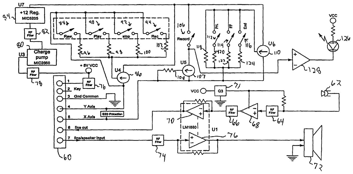
Internal electrical and electronic components of the hand microphone10and contained in the housing12will now be described with reference toFIG. 5.
The six conductors of the signal connection cord26(FIG. 1) are terminated at a Berg connector60(FIG. 5) after being wound around a ferrite bead (not shown) to suppress RF interference. One of the conductors of the signal connection cord carries an analog audio signal which originates at a conventional microphone62. The signal from microphone62is filtered at components labeled64and66, and amplified at amplifier stages68and70. Filtered power for the amplifier stage68is provided via a power filter element71. In a preferred embodiment of the invention, the amplifier stage68provides a gain factor of 20 and the amplifier stage70provides a gain factor of 6. The amplified audio signal outputted from amplifier stage70is coupled to the respective conductor of the connection cord26for transmission to the personal computer via the adaptor module32.
An analog audio signal which is output from the sound card of the personal computer is transmitted to the hand microphone via another connector of the cord26and is applied to drive a speaker72after being filtered and amplified at filter74and amplifier stage76, respectively. In a preferred embodiment the amplifier stage76provides a gain factor of 12.
Two more of the six conductors of the connection cord26are used for power and ground connections, respectively. A 5-volt power signal sourced from the game port of the personal computer and transmitted through the connection cord26is filtered at filter stages76,78and then boosted to an unregulated 13.25 volts by charge pump80. The boosted power level is filtered at filter stage82and then is regulated down to a 12-volt power supply level at regulator84. The resulting 12-volt power is used to derive two analog control signals which are outputted from the hand microphone to the game port of the personal computer. One of the control signals, which is applied through a conductor of the connection cord26and the adaptor module32to the Y-axis input of the game port, is generated by a combination of a constant current source86and a switch/resistor network made up of switches88,90,92and94and resistors96,98,100and102.
The switches88,90,92and94shown inFIG. 5correspond to respective positions of the slide switch18shown inFIG. 1and when closed respectively actuate the “rewind”, “play”, “stop” and “record” functions. When switch88is closed, the current from constant current source86is allowed to flow through resistor96; when switch90is closed, the current from current source86is allowed to flow through resistor98; when switch92is closed, current from the current source86is allowed to flow through resistor100; and when switch94is closed, current from the current source86is allowed to flow through resistor102. The respective values of the resistors96-102are selected so as to generate easily distinguishable voltage levels. In a preferred embodiment of the invention, the resistor values are selected as follows:
Resistor 96:681 ohmsResistor 98:897 ohmsResistor 100:1,100 ohmsResistor 102:1,580 ohms
When the slide switch18is in its record position, this also causes closure of a switch106inFIG. 5. When switch106is closed, a current provided by constant current source107is allowed to flow through resistor108to provide one of the signal levels that is ultimately provided, via a last one of the conductors of connection cord26, as an X-axis input to the game port of the personal computer. In a preferred embodiment the resistor108has a value of 357 ohms.
The other levels for the X-axis input signal are generated by a constant current source110and a switch/resistor network made up of switches112,114,116and resistors118,120,122and124. The switches112,114and116correspond to respective ones of the push button switches20,22and24shown inFIG. 1. When switch112is closed, current from the constant current source110is allowed to flow through resistor120; when switch114is closed, current from the current source110is allowed to flow through resistor122; and when switch116is closed, current from the current source110is allowed to flow through resistor124. The resistor118is always connected to current source110and provides an idle level for the X-axis control signal. Again, the resistor values are selected to provide easily distinguishable control signal levels which correspond to the various control functions, and in a preferred embodiment of the invention the resistor values are as follows:
Resistor 118:1,910 ohmsResistor 120:887 ohmsResistor 122:2,100 ohmsResistor 124:3,240 ohms
The switch106, which is closed to actuate the “record” function, also controls an LED126via a Darlington switch128. The LED126(also shown inFIG. 1) performs the conventional function of providing a visual indication when the record function is being carried out.
FIG. 6is a simplified block diagram which shows the hand microphone10of the present invention interfaced to a personal computer140so that the hand microphone10can be used to control the PC140to perform dictation functions. It is to be understood from previous discussion that the PC140may be connected to other PC's (not shown) via a network facility (not shown). The PC140includes conventional elements such as a display142, a keyboard and mouse (collectively indicated by reference numeral144), a sound card146and a game port148, and working and mass data storage elements (which are not separately shown).
The adaptor32is mounted to the game port148(via the connector40shown inFIG. 4) and, together with the cords26,46and48, provides a number of signal paths between the hand microphone10and the PC140. In particular, a first signal path is provided by one of the conductors in cord126, the adaptor32and one of the cords46or48as an input analog audio signal path to the sound card146. A second signal path provides an analog signal level via cord26and adaptor32as an X-axis input to the game port148. A third signal path, also provided through the cord26and the adaptor32, provides an analog control signal level as a Y-axis input to the game port. A fourth signal path is provided for transmitting an analog audio signal outputted from the sound card to the hand microphone10via one of the connection cords46,48, the adaptor32and the cord26.
Additionally, ground and power signal paths are provided through the adaptor32and the cord26so that the hand microphone10is powered from the game port148.
The game port148reads the above-mentioned control signal levels applied to the X- and Y-axis inputs of the game port148according to a conventional technique. The PC140is programmed to enter into a dictation mode of operation upon receipt of a suitable signal via the keyboard or mouse, and when in the dictation mode interprets the control signal levels in a manner to implement conventional dictation functions such as record, play, fast forward, rewind and so forth. It will be understood that when the “record” function is invoked, the voice signals generated at the microphone10are processed by the sound card146and stored by the PC140in the form of digital data according to known practices. When the “play” function is actuated through the hand microphone10, the PC140reads previously recorded sound data and reproduces the sound data through the sound card146as an analog audio output signal that is audibly played back through the speaker component of the hand microphone10.
It is well within the abilities of those having ordinary skill in the art to create the software required to program the PC140to perform the functions referred to in the preceding paragraph.
According to a preferred embodiment of the invention, the PC140is also programmed so as to be selectively operable in a “calibration mode”, in which the PC140collects data which enables the PC to accurately detect the correspondence between the varying X-input and Y-input signals and the dictation control functions which those signal levels are intended to invoke. When the PC140is placed in the calibration mode, the display142of the PC is caused to provide a screen display like that shown inFIG. 7. It is believed that the information conveyed byFIG. 7is self-explanatory, and it is well within the abilities of those who are skilled in the art to program the PC140to provide the screen display ofFIG. 7and the calibration function represented by that screen display.
The hand microphone assembly provided according to this invention makes use of the signal detection capabilities of a standard PC game port to duplicate the sophisticated dictation control capabilities of more expensive hand microphone equipment. By providing two separate analog control signal channels, the hand microphone supports a rather large number of distinct control functions represented by signals that can be detected with a high degree of reliability and accuracy. Also, the provision of two separate control signal channels makes it possible to invoke simultaneously two different control functions.
The embodiment of the invention as described above includes one connection cord26to join the hand microphone10to the adaptor module32. However, it is within the contemplation of the invention to provide one or more additional connection cords in series, preferably joined to each other by the standard RJ-14 plug and jack arrangements referred to above. It is also contemplated that a plastic rest for the hand microphone may be interposed as part of the signal path between the hand microphone10and the adaptor module32. Provision of a suitable rest for the microphone with a suitable combination of plugs and/or jacks is also well within the abilities of those who are skilled in the art.
In the circuit arrangement illustrated inFIG. 5, the control signal levels are generated by using constant current sources coupled to resistor networks. This approach was chosen to enhance the precision of the generated signal levels, but other approaches are contemplated by the invention, including use of voltage dividers and/or potentiometers.
It is to be understood that the above description may indicate to those skilled in the art additional ways in which the principles of this invention may be used without departing from the spirit of the invention. For example, the number and types of dictation control functions to be invoked by the hand microphone may be changed. Also, the distribution of the control functions between the X-axis input channel and the Y-axis input channel is subject to change without departing from the invention. The particularly preferred embodiments of the apparatus are thus intended in an illustrative and not limiting sense. The true spirit and scope of the invention are set forth in the following claims.
Claims
- A method of controlling dictation functions performed by a personal computer having a game port, the method comprising the steps of: providing a hand microphone assembly, operatively connected to said personal computer, said microphone assembly comprising a microphone and further comprising a first and a second switch each electrically connected to corresponding first and second resistor networks and at least one constant current source, said first switch, said first resistor netxxork, and said constant current source operatively configured to generate a first analog control signal level, said second switch, said second resistor network, and said constant current source operatively configured to generate a separate second analog control signal level;receiving inputs applied to said switches and, using the hand microphone in response, generating said first analog control signal level and said separate second analog control signal;applying said first analog control signal level as an X-axis input to said game port of said personal computer;and applying said second analog control signal level as a Y-axis input to said game port of the said personal computer.
- A method according to claim 1 , wherein said hand microphone is operatively connected to said personal computer by means of a connection card and an adapter module.
- The method according to claim 1 wherein at least one of said corresponding resistor networks is a voltage divider.
- The method according to claim 1 wherein at least one of said corresponding resistor networks is a potentiometer.
- The method according to claim 1 , wherein said hand microphone further comprises at least one audio amplifier providing a gain factor of between about 6 and about
- The method according to claim 1 , wherein at least one of said switches is programmable.
- The method according to claim 6 wherein at least one of said switches is programmable to perform at least one function selected from the group consisting of record, stop, play, rewind, fast forward, end, send and priority.
- The method according to claim 1 , wherein said hand microphone is operatively connected to said personal computer via a sound card.
Disclaimer: Data collected from the USPTO and may be malformed, incomplete, and/or otherwise inaccurate.