U.S. Pat. No. 7,641,550
GAME DEVICE CHANGING ACTION OF GAME OBJECT DEPENDING ON INPUT POSITION, STORAGE MEDIUM FOR STORING GAME PROGRAM AND METHOD USED IN GAME DEVICE
AssigneeNintendo Co., Ltd.
Issue DateMarch 30, 2005
Illustrative Figure
Abstract
A game device 1 that executes a game program stored in a storage medium of the present invention detects and stores coordinates on a game image corresponding to an input while the input by the player is detected. Then, based on an input locus having a predetermined shape shown by the stored coordinates, a direction shown by the input locus is calculated. When the direction is calculated, the game device determines whether or not a coordinate of a starting point is included in a predetermined range 35 that is based on coordinates showing a position in which the player object 32 is displayed in the game image. When it is determined that the coordinate of the starting point is included in the predetermined range 35, the player object 32 performs a moving action in the calculated direction. When it is determined that the coordinate of the starting point is not included in the predetermined range 35, the player object 32 performs a kicking action in the calculated direction.
Description
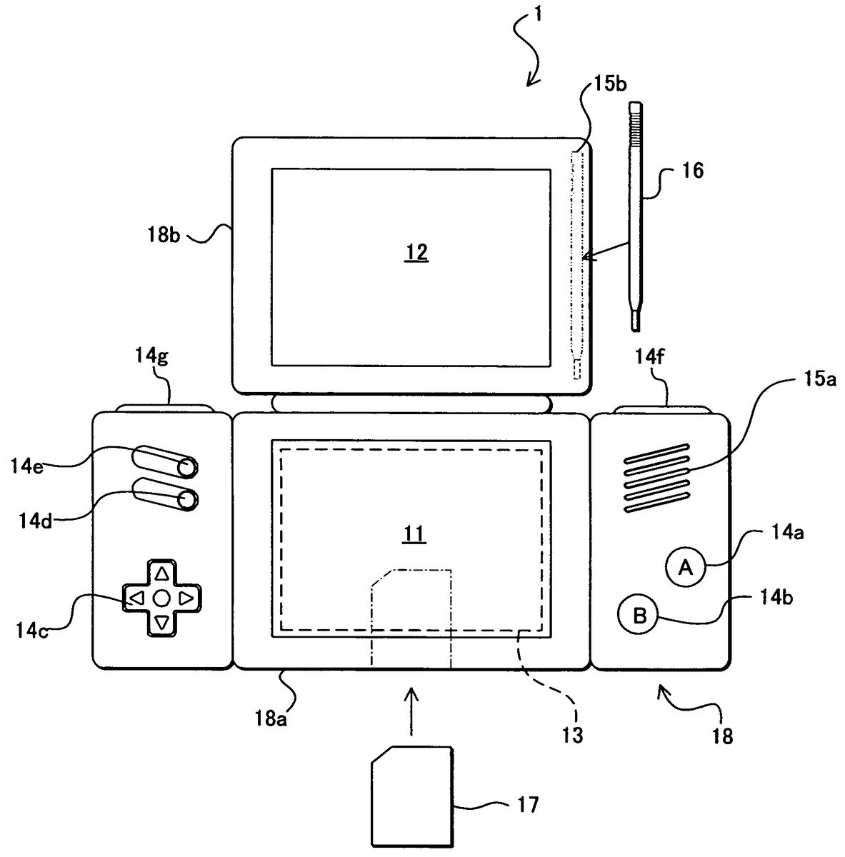
DESCRIPTION OF THE PREFERRED EMBODIMENTS FIG. 1is an appearance view of a portable game device for executing a game program according to an exemplary embodiment. InFIG. 1, the game device1of this exemplary embodiment is housed in a housing18in such a manner that two liquid crystal displays (hereinafter, referred to as “LCD”)11and12are arranged in predetermined positions. More specifically, when a first LCD11and a second LCD12are arranged in the vertical direction, the housing18consists of a lower housing18aand an upper housing18b. The upper housing18bis supported so as to be rotatable in a portion of the upper side of the lower housing18a. The upper housing18bhas a slightly larger flat-face shape than that of the second LCD12, and has an opening formed so as to expose the display screen of the second LCD12from its main flat-face on one side. The lower housing18ahas an opening formed so as to expose the display screen of the first LCD11substantially in the central portion in the horizontal direction. The flat-face shape of the lower housing18ais selected so as to be longer in the horizontal direction than that of the upper housing18b. In the lower housing18a, a sound-through hole15aof a speaker15is formed in either one of the portions sandwiching the first LCD11, and an operation switch portion14is provided in the left and the right that sandwich the first LCD11. The operation switch portion14includes action switches14aand14bthat are provided on a main flat-face on one side of the lower housing18aon the right of the first LCD11, and a direction designating switch14c, a start switch14d, and a selection switch14ethat are provided on a main flat-face on one side of the lower housing18aon the left of the first LCD11. The action switches14aand14bare used to, for example, instruct a player object to jump, punch, move a weapon or the like in an action game, and ...
DESCRIPTION OF THE PREFERRED EMBODIMENTS
FIG. 1is an appearance view of a portable game device for executing a game program according to an exemplary embodiment. InFIG. 1, the game device1of this exemplary embodiment is housed in a housing18in such a manner that two liquid crystal displays (hereinafter, referred to as “LCD”)11and12are arranged in predetermined positions. More specifically, when a first LCD11and a second LCD12are arranged in the vertical direction, the housing18consists of a lower housing18aand an upper housing18b. The upper housing18bis supported so as to be rotatable in a portion of the upper side of the lower housing18a. The upper housing18bhas a slightly larger flat-face shape than that of the second LCD12, and has an opening formed so as to expose the display screen of the second LCD12from its main flat-face on one side. The lower housing18ahas an opening formed so as to expose the display screen of the first LCD11substantially in the central portion in the horizontal direction. The flat-face shape of the lower housing18ais selected so as to be longer in the horizontal direction than that of the upper housing18b. In the lower housing18a, a sound-through hole15aof a speaker15is formed in either one of the portions sandwiching the first LCD11, and an operation switch portion14is provided in the left and the right that sandwich the first LCD11.
The operation switch portion14includes action switches14aand14bthat are provided on a main flat-face on one side of the lower housing18aon the right of the first LCD11, and a direction designating switch14c, a start switch14d, and a selection switch14ethat are provided on a main flat-face on one side of the lower housing18aon the left of the first LCD11. The action switches14aand14bare used to, for example, instruct a player object to jump, punch, move a weapon or the like in an action game, and to input an instruction for acquisition of an item and selection and determination of a weapon or a command in a roll playing game (RPG) or simulation RPG. The direction designating switch14cis used to designate a direction on a game screen, such as designating a direction in which a player object (or player character) that can be operated by the player is to move, designating the moving direction of the cursor or the like. If necessary, an action switch can be additionally provided, or side switches14fand14gcan be provided on the left and the right of the upper surface (upper side surface) of the area in the lower housing18ain which the operation switches14are provided.
Furthermore, a touch panel13(area defined by a broken line inFIG. 1) is provided on the top surface of the first LCD11. The touch panel13may be of any kind, for example, a resistive film system, an optical system (infrared ray system), or capacitive coupling system, as long as it detects the coordinate position of a stick16and outputs coordinate data when a pressing operation, a moving operation or a touching operation is performed on the top surface thereof with the stick16(or possibly with a finger).
A housing hole15b(dashed double dotted line inFIG. 1) for housing the stick16for operation to the touch panel13, if necessary, is formed near the side of the upper housing18b. The stick16is housed in this housing hole15b. A cartridge insertion portion (dashed dotted line inFIG. 1) in which a game cartridge17(hereinafter, simply referred to as “cartridge17”) containing a memory (e.g., ROM) that stores a game program is removably mounted is formed in a portion of the side of the lower housing18a. The cartridge17is an information storage medium for storing a game program, and for example, a non-volatile semiconductor memory such as ROM or a flash memory can be used for this. A connector (seeFIG. 2) for electrical connection to the cartridge17is contained inside the cartridge insertion portion. An electronic circuit board on which various electronic components such as CPU are mounted is housed in the lower housing18a(or possibly in the upper housing18b). The information storage medium for storing a game program is not limited to the non-volatile semiconductor memory, but may be CD-ROM, DVD, or similar optical disk storage media.
Next, referring toFIG. 2, the internal configuration of the game device1will be described.FIG. 2is a block diagram showing the internal configuration of the game device1. InFIG. 2, a CPU core21is mounted in the electronic circuit board housed in the housing18a. A connecter28for connection to the cartridge17is connected to the CPU core21via a predetermined bus, and an input/output interface (I/F) circuit27, a first graphic processing unit (first GPU)24, a second graphic processing unit (second GPU)26, and a working RAM (WRAM)22are also connected to the CPU core21via predetermined buses.
The cartridge17is removably connected to the connector28. The cartridge17is a storage medium for storing a game program, as described above. More specifically, a ROM171for storing a game program and a RAM172for rewritably storing backup data are mounted therein. The game program stored in the ROM171of the cartridge17is loaded onto the WRAM22, and the game program loaded onto the WRAM22is executed by the CPU core21. Data for generating temporary data or images that are obtained by the CPU core21executing the game program are stored in the WRAM22.
The touch panel13, the operation switch portion14, and the speaker15are connected to the I/F circuit27. The speaker15is positioned on the inner side of the sound-through hole15b.
A first video RAM (hereinafter, referred to as “VRAM”)23is connected to the first GPU24, and a second video RAM (hereinafter, referred to as “VRAM”)25is connected to the second GPU26. The first GPU24generates a first game image, based on data for generating an image stored in the WRAM22, in response to an instruction from the CPU core21. The generated first game image is rendered in the first VRAM23by the first GPU24. The second GPU26generates a second game image, based on data for generating an image stored in the WRAM22, in response to an instruction from the CPU core21. The generated second game image is rendered in the second VRAM25by the second GPU26.
The first VRAM23is connected to the first LCD11, and the second VRAM25is connected to the second LCD12. The first GPU24outputs the first game image rendered in the first VRAM23to the first LCD11in response to an instruction from the CPU core21. Then, the first LCD11displays the first game image output from the first GPU24. The second GPU26outputs the second game image rendered in the second VRAM25to the second LCD12in response to an instruction from the CPU core21. Then, the second LCD12displays the second game image output from the second GPU26.
Hereinafter, the game process executed in the game device1by a game program stored in the cartridge17will be described. According to certain exemplary embodiments, only the first LCD11whose display screen is covered with the touch panel13is used as the display device. Therefore, the game device that executes a game program according to the present invention may have a structure in which the second LCD12is not included. In other words, the game program according to the present invention may be executed by a game device, PDA or the like that includes only one display device.
FIG. 3is a view showing an example of a game image in this embodiment. This embodiment will be described by taking a soccer (futsal) game as shown inFIG. 3. The game image displayed in the first LCD11includes a field31, a plurality of player objects32representing soccer players and a ball (ball object)33. The players play a soccer game by operating the plurality of player objects32, using the touch panel13. For example, the player plays a soccer game by operations such as moving the player objects32and letting the player objects32kick the ball.
FIGS. 4A to 4Dare views for illustrating the manner of operation in the soccer game in this embodiment. In this embodiment, the operation of the players to the player objects32includes the following two operations. A first operation is to moving the player objects32(moving operation). When a player object32is holding (keeping) the ball, the moving operation is an operation of letting the player object32dribble. A second operation is an operation of letting the player object32that is keeping the ball kick the ball (kicking operation). The player performs the moving operation and the kicking operation, using the touch panel13.
FIG. 4Ais a view for illustrating the moving operation. When performing the moving operation, the player performs an action of drawing a straight line on the touch panel13. Specifically, an input of drawing a line starting from the vicinity of the player object32displayed on the screen with a finger34is performed on the touch panel13. More specifically, when the locus of an input (input locus) of the player with respect to the touch panel13is originated from within a determination area35including a player object32, the moving operation is performed with respect to that player object32. Herein, the determination area35is set for each player object32. The size of the determination area35is previously determined. In this embodiment, the shape of the determination area is a circle with the position of the player object (the center of the player object displayed on the screen) as its center. The determination area35moves together with the player object32.FIGS. 4A to 4Dshow the determination area35, but in this embodiment, the determination area35is not actually shown in the screen.
The arrow shown inFIG. 4Arepresents an input locus. The player performs an input so that the input locus results in a straight line extending in the direction in which the player desires to move the player object32. In other words, in the case of the moving operation, the player object32moves in the direction in which the straight line of the input locus extends. Thus, the player can move the player object32in the direction in which the input locus extends. InFIG. 4A, this embodiment has been described by taking a player object32holding a ball (player object32keeping a ball) as an example, but the moving operation can be performed in the same manner when the player object32does not hold a ball.
FIGS. 4B,4C and4D are views for illustrating the kicking operation. When performing the kicking operation, in the same manner as performing the moving operation, the player performs an action of drawing a straight line on the touch panel13. Specifically, an input locus whose starting point is outside of the determination area35is inputted on the touch panel13. The player object32that is to kick the ball is a player object the determination area35of which is included in the input locus. In this case, the ending point of the input locus may be within the determination area35and be ahead of the player object32, as shown inFIG. 4B, or may be within the determination area35and be backward from the player object32, as shown inFIG. 4C. Alternatively, the ending point of the input locus may be in a position at which the input locus traverses the determination area35, that is, a position outside of the determination area35, as shown inFIG. 4D. The player performs an input in such a manner that the straight line of the input locus extends in the direction in which the player desires to let the player object32kick the ball33. In other words, in the case of the kicking operation, the ball33moves in the direction in which the straight line of the input locus extends. Thus, the player can let the player object32perform the operation of kicking a ball in the direction in which the input locus extends.
As described above, in this embodiment, the player can perform the moving operation and the kicking operation by drawing a linear input locus on the touch panel13. In other words, in this embodiment, it is possible to operate two different operations of the moving operation and the kicking operation with one kind of action of drawing a linear input locus. A single action allows a plurality of kinds of operations, so that the player can perform the game operation in a simple manner. In this embodiment, the direction in which the linear input locus extends is the direction that is designated by the player, that is, the direction in which the player object32or the ball33moves. Hereinafter, the direction in which the input locus extends is referred to as a “designated direction”.
Next, an example of screen display of the game in this embodiment will be described.FIGS. 5A to 5Dare views showing an example of screen display when performing the moving operation. InFIGS. 5A to 5D, a portion of the field31that is enlarged, compared with the game image shown inFIG. 3, is displayed, and only one player object of the plurality of player objects is displayed. In this embodiment, as the game image, the entire field31, which is a game space, may be displayed, or only a portion of the field31may be displayed. In the example of display screen shown inFIG. 5A, the player object32is in a halt state on the field31. In this state, when the player performs the moving operation of designating a direction to the upper left on the screen (FIG. 5A), the player object32starts an action of moving in the upper left direction (FIG. 5B). In this embodiment, the direction in which the player object32is to move is determined after the end of the moving operation, and after the determination of the direction, the moving action of the player object32starts. The player object32continues to move in the designated direction until the player performs the next moving operation. When the moving operation of designating a direction different from the present moving direction is performed during the movement of the player object32(FIG. 5C), the player object32starts to move in the direction designated by the new moving operation (FIG. 5D).
FIGS. 6A to 6Dare views showing an example of screen display when performing the kicking operation. In the example of display screen shown inFIG. 6A, the player object32is in a halt state, keeping the ball33. In this state, when the player performs the kicking operation with respect to the player object32, the player object32starts an action of kicking the ball33(kicking action) toward the designated direction for the kicking operation (FIG. 6B). In the example of display screen shown inFIG. 6C, the player object32is dribbling, that is, the player object32is moving together with the ball33. When the player performs the kicking operation in this state (FIG. 6C), the player object32performs an action of kicking the ball33in the designated direction for the kicking operation, and then continues to move in the designated direction for the moving operation (FIG. 6D). The ball33moves toward the designated direction for the kicking operation. The position at which the player object32performs the action of kicking the ball is the position at which the kicking operation has ended, that is, the position of the player object32at the point when the finger of the player is detached from the touch panel13.
Next, the detail of the game process executed by the game device1will be described. First, data stored in the WRAM22during the game process will be described.FIG. 7is a view showing a memory map of the WRAM22of the game device1. As shown inFIG. 7, during the game process, input coordinate data40, designated direction data41, player object data42, ball data43, locus-process ongoing flag44, moving subject data45, and kicking subject data46are stored in the WRAM22.
The input coordinate data40represents a coordinate (input coordinate) on the game screen in response to the input to the touch panel13. The input coordinate data40contains a group of coordinate values showing the results of continuous input at one time. In other words, data of an input coordinate is added and stored in the WRAM22while input to the touch panel13by the player is continuously detected. The data of input coordinates are not erased during the period in which the input is detected, and when different input is newly detected, the input coordinate data40showing the previous input is erased. The designated direction data41shows the designated direction that is determined based on the coordinate values shown by the input coordinate data40.
The player object data42represents various information regarding the state of the player object. More specifically, the player object data42includes player position data421and player moving direction data422. The player position data421represents the position of the player object on the field. The player moving direction data422represents the moving direction of the player object. The player object data42includes speed data representing the moving speed of the player object, ID for identifying the player object and the like. InFIG. 7, only one kind of player object data42is shown, but the player object data42is prepared for every player object that appears in the game.
The ball data43represents various information regarding the state of the ball. More specifically, the ball data43includes ball position data431, ball moving direction data432and keep-state data433. The ball position data431represents the position of the ball on the field. The ball moving direction data432represents the moving direction of the ball. The keep-state data433represents whether or not the ball is kept and which player object is keeping the ball when the ball is kept. More specifically, when the ball is kept, the ID of the player object that is keeping the ball is set in the keep-state data433. When the ball is not kept, data representing “undetermined” is set in the keep-state data433. In the initial state at the game start, the keep-state data433represents “undetermined”.
The locus-process ongoing flag44shows whether or not the player is in the process of inputting to the touch panel13. More specifically, while the player is in the process of inputting to the touch panel13, the status in which the locus-process ongoing flag44is up (ON status) is set. While the player is not in the process of inputting to the touch panel13, the status in which the locus-process ongoing flag44is down (OFF status) is set.
The moving subject data45represents the player object that is subjected to the moving operation. More specifically, when there is a player object that is subjected to the moving operation, the ID of this player object is set in the moving subject data45. On the other hand, when no player object is subjected to the moving operation, data representing “undetermined” is set in the moving subject data45. The kicking subject data46represents the player object that is subjected to the kicking operation. More specifically, when there is a player object that is subjected to the kicking operation, the ID of this player object is set in the kicking subject data46. On the other hand, when no player object is subjected to the kicking operation, data representing “undetermined” is set in the kicking subject data46.
Next, the flow of the game process executed in the game device1by the game program according to the present invention will be described with reference toFIGS. 8 to 10.FIG. 8is a flowchart showing the flow of the game process executed in the game device1. When the power source of the game device1is turned on, the CPU core21of the game device1executes a start program stored in a boot ROM (not shown), and initializes the units such as the WRAM22. Then, the game program stored in the cartridge17is read in the WRAM22, and execution of the game program starts. Consequently, a game image is displayed in the first LCD11via the first GPU24, and thus the game is started. The flowchart shown inFIG. 8shows the game processes after the game is started.
InFIG. 8, first in step50(“step” is referred to as “S” in the drawings), a game image including player objects, a ball and a field is displayed in the first LCD11. More specifically, a portion of or the entire area of the field and the player objects and the ball positioned within that area are displayed. The position of each player object is determined based on the player position data421stored in the WRAM22. The position of the ball is determined based on the ball position data431stored in the WRAM22. At the start of the game, predetermined initial values are set for the player position data421and the ball position data431. After the game is started, in steps55,57and58, which will be described later, the player position data421and the ball position data431are updated, and consequently, the player object and the ball are moved and displayed. The processes of steps50to59are performed during one frame from when one game image is displayed to when the next game image is displayed.
In step51next to step50, it is determined whether or not the player object is within a predetermined distance from the ball. This predetermined game program is previously determined in the game program. The determination in step51is performed by comparing the ball position data431and the player position data421of each player object. In the determination in step51, it is determined that there is no player object within the predetermined distance from the ball, the process of step52is skipped and the process of step53is performed. On the other hand, in the determination in step51, it is determined that there is a player object within the predetermined distance from the ball, the process of step52is performed. That is, in step52, the ball is set in the keep-state with respect to the player object that is the nearest to the ball. More specifically, the keep-state data433stored in the WRAM22is updated so as to represent the ID of the player object that is the nearest the position of the ball. Thus, in the processes after this step, it is determined that the ball is kept by the player object that is the nearest to the position of the ball. After the process of step52, the process of step53is performed.
In step53, a process of determining an object action is performed. The process of determining an object action is a process of determining the moving direction of the player object and the ball. Hereinafter, the detail of the process of determining an object action will be described with reference toFIG. 9.
FIG. 9is a flowchart showing the flow of the detailed process of step53shown inFIG. 8. In the process of determining an object action, first, in step60, an input to the touch panel13by the player is detected. More specifically, the CPU core21acquires the input coordinate showing the position of the input from the touch panel13. In the following step61, the input coordinate acquired in step60is stored in the WRAM22. More specifically, data representing the input coordinate is added to the input coordinate data40. When there is no input to the touch panel13by the player, no coordinate value is acquired in step60, and no data is stored in the WRAM22in step61.
In step62next to step61, it is determined whether or not there has been an input to the touch panel13by the player. This determination is performed based on whether or not the input coordinate was acquired in step60. In the determination of step62, when it is determined that there was an input to the touch panel13by the player, the process of step63is performed. That is to say, the processes of steps63to70are performed while the player is in the process of inputting to the touch panel13. On the other hand, in the determination of step62, when it is determined that there was no input to the touch panel13, the process of step71is performed. That is to say, the processes of steps71to73are performed when there is no input to the touch panel13.
First, the processes that are performed while the player in the process of inputting to the touch panel13(steps63to70) will be described. In step63, it is determined whether or not the locus-process ongoing flag44stored in the WRAM22is up. The process of step63is a process for determining whether or not the input by the player has just started (i.e., the starting point of the input locus has just been detected) or the input by the player already has been started (i.e., a point after the starting point of the input locus has been detected). In the determination in step63, when the locus-process ongoing flag44is up, the step64is performed. On the other hand, in the determination in step63, when the locus-process ongoing flag44is not up, the step69is performed. Therefore, at the point when an input to the touch panel13by the player is detected for the fist time, the process of step64is performed, and during the period in which the input continues after that, the process of step69is performed.
First, the processes that are performed at the point when an input to the touch panel13by the player is detected for the first time (steps64to68) will be described. In step64, the status is updated to a status in which the locus-process ongoing flag44stored in the WRAM22is up. In the following step65, the kicking subject data46is set to “undetermined”. More specifically, the content of the kicking subject data46stored in the WRAM22is updated to the content showing “undetermined”.
In step66next to step65, it is determined whether or not the input coordinate is included in the determination area of any player object. Here, the input coordinate is the input coordinate stored as the input coordinate data40in the immediately previous step61. In step66, the input coordinate is a coordinate representing the starting point of the input locus. Therefore, the process of step66is a process for determination as to whether or not the starting point of the input locus by the player is positioned within the determination area, that is, whether or not the operation of the player is a movement operation.
The process of the step66is performed by comparing the player position data421of each player object with the input coordinate stored as the input coordinate data40in the immediately previous step61. More specifically, the coordinate represented by each player position data421(coordinate on the field) is converted into a coordinate representing the position on the screen, and the distance between each converted coordinate and the input coordinate is calculated. As a result, there is player position data421for which the calculated distance is shorter than a specific (predetermined) distance, it is determined that the input coordinate is included in the determination area of the player object corresponding to the player position data421. That is to say, it is determined that the operation of the player is a moving operation. On the other hand, there is no player position data421for which the calculated distance is shorter than the specific distance, it is determined that the input coordinate is not included in the determination area of any player object. That is to say, it is determined that the operation of the player is not a moving operation.
In the determination in step66, when it is determined that the input coordinate is not included in the determination area of any player object (i.e., it is determined that the operation of the player is not a moving operation), the process of step67is performed. More specifically, in step67, the moving subject data45stored in the WRAM22is set to “undetermined”. After step67, the process of determining an object action shown inFIG. 9ends. On the other hand, in the determination in step66, when it is determined that the input coordinate is included in the determination area of any player object (i.e., it is determined that the operation of the player is a moving operation), the process of step68is performed. That is, in step68, the moving subject data45is set. More specifically, the content of the moving subject data45stored in the WRAM22is updated so as to represent the ID of the player object for which it was determined that input coordinate is included in the determination area in step66. After step68, the process of determining an object action shown inFIG. 9ends.
Next, the processes (steps69and70) that are performed during a period after an input to the touch panel13by the player is first detected and the input continues will be described. In step69, it is determined whether or not the input coordinate is included in the determination area of any player object. Here, the input coordinate is the input coordinated stored as the input coordinate data40in the immediately previous step61. In step69, the input coordinate is a coordinate representing a point on the input locus (a point that is not the starting point). Therefore, the process of step69is a process for determining whether or not a point on the input locus by the player is within the determination area, that is, whether or not the operation by the player is a kicking operation. The detailed process content of step69is the same as step66described above.
In the determination of step69, when it is determined that the input coordinate is not included in the determination area of any player object (the operation by the player is not a kicking operation), the process of determining an object action shown inFIG. 9ends. On the other hand, in the determination of step69, when it is determined that the input coordinate is included in the determination area of any player object (the operation by the player is a kicking operation), the process of step70is performed. That is, in step70, the kicking subject data46is set. More specifically, the content of the kicking subject data46stored in the WRAM22is updated so as to represent the ID of the player object for which it was determined that input coordinate is included in the determination area. After step70, the process of determining an object action shown inFIG. 9ends.
As shown in the above steps63to70, while an input is performed by the player, it is determined whether or not the input is a moving operation and whether or not the input is a kicking operation (steps66and69). When the input is a moving operation, the player object that is subjected to the moving operation is specified (step68). When the input is a kicking operation, the player object that is subjected to the kicking operation is specified (step70).
Next, the processes (steps71to73) that are performed when there is no input to the touch panel13by the player will be described. In step71, it is determined whether or not the locus-process ongoing flag44stored in the WRAM22is up. In the determination of step71, when the locus-process ongoing flag44is up, the processes of steps72and73are performed. On the other hand, in the determination of step71, when the locus-process ongoing flag44is not up, the processes of steps72and73are skipped, and the process of determining an object action shown inFIG. 9ends. The process of step71is a process for determining whether or not that point of time is immediately after the input to the touch panel13by the player is stopped. Then, when it is immediately after the input to the touch panel13by the player is stopped, the process (step73, which will be described later) for determining the direction in which the player object and/or the ball moves is performed.
In step72, the status is changed to one in which the locus-process ongoing flag44stored in the WRAM22is down. In the following step73, the process of determining a designated direction is performed. The process of determining a designated direction refers to a process for determining the designated direction of the moving operation or the kicking operation by the player and determining the moving direction of the player object and/or the ball. Hereinafter, the process of determining a designated direction will be described more specifically with reference toFIG. 10.
FIG. 10is a flowchart showing the flow of the detailed process of step73shown inFIG. 9. In the process of determining a designated direction, first, in step80, a designated direction is calculated. In this embodiment, the designated direction is calculated based on the starting point and the ending point of the input locus. More specifically, a vector connecting the starting point to the ending point of the input locus is calculated as the vector showing the designated direction. Data representing the coordinates of the staring points and the ending point of the input locus are included in the input coordinate data40stored in the WRAM22. The data of the vector showing the designated direction calculated in step80is stored as the designated direction data41in the WRAM22.
In step81next to step80, it is determined whether or not the magnitude of the vector showing the designated direction calculated in step80is 0. In the determination of step81, when the magnitude of the vector showing the designated direction is 0, the process of determining a designated direction ends. On the other hand, in the determination of step81, when the magnitude of the vector showing the designated direction is not 0, the process of step82is performed. That is, in step82, it is determined whether or not the moving subject data is set. As described above, the fact that the moving subject data has been set means that the player has performed a moving operation. In other words, the process of step82is a process for determining whether or not the immediately previous operation is a moving operation.
More specifically, when the moving subject data is set in step82, that is, when the immediately previous operation is a moving operation, the process of step83is performed. That is, in step83, the moving direction of the player object that is subjected to the moving operation is set to the designated direction. More specifically, the content of the player moving direction data422stored in the WRAM22is updated to the content showing the vector of the designated direction calculated in step80. Thus, in step55for later, the player object moves in the designated direction. The player object for which the content of the player moving direction data422is updated in step83is a player object represented by the moving subject data45. After step83, the process of determining a designated direction ends.
On the other hand, when the moving subject data is not set in step82, that is, when the immediately previous operation is not a moving operation, the process of step84is performed. That is, in step84, it is determined whether or not the kicking subject data is set. As described above, the fact that the kicking subject data has been set means that the player has performed a kicking operation. In other words, the process of step84is a process whether or not the immediately previous operation is a kicking operation.
More specifically, when the kicking subject data is not set in step84, that is, when the immediately previous operation is not a kicking operation, the process of determining a designated direction ends. On the other hand, when the kicking subject data is set in step84, that is, when the immediately previous operation is a kicking operation, the process of step85is performed. That is, in step85, the moving direction of the ball is set to the designated direction. More specifically, the content of the ball moving direction data432stored in the WRAM22is updated to the content showing the vector of the designated direction calculated in step80. Thus, in step58for later, the ball moves in the designated direction. In step86next to step85, the state in which the ball is kept is cancelled. More specifically, the content of the keep-state data433stored in the WRAM22is updated to data representing “undetermined”. After step86, the process of determining a designated direction ends.
When the process of determining a designated direction ends, the process of determining an object action shown inFIG. 9ends. When the process of determining an object action ends, the process of step54shown inFIG. 8is performed.
Referring back toFIG. 8, in step54, it is determined whether or not a player object that is moving is displayed. Here, a player object that is moving is a player object represented by the moving subject data45. In the determination of step54, when it is determined that no moving player object is displayed, the process of step55is skipped, and the process of step56is performed. On the other hand, in the determination of step54, when it is determined that a moving player object is displayed, the process of step55is performed. That is, in step55, the position in which the player object is displayed is updated in accordance with the moving direction and the speed of the moving player object. More specifically, the player position data421stored in WRAM22is updated, based on the moving direction and the speed of the moving player object. Here, the moving direction and the speed of the moving player object are represented by the player moving direction data422and the speed data stored in the WRAM22.
In step56next to step55, it is determined whether or not the ball is kept. The determination of step56is performed by referring to the content of the keep-state data433stored in the WRAM22. That is, when the keep-state data433represents “undetermined”, it is determined that the ball is not kept, and when the keep-state data433represents other than “undetermined”, it is determined that the ball is kept.
When it is determined that the ball is kept in the determination of step56, the process of step57is performed. That is, in step57, the position in which the ball is displayed is updated in accordance with the position of the player object that is keeping the ball. More specifically, the content of the ball position data431stored in the WRAM22is updated to a position represented by the player position data421of the player object that is keeping the ball. Here, the player object that is keeping the ball is a player object represented by the keep-state data433. On the other hand, when it is determined that the ball is not kept in the determination of step56, the process of step58is performed. That is, in step58, the position in which the ball is displayed is updated in accordance with the moving direction and the speed of the ball. More specifically, the content of the ball position data431stored in WRAM22is updated, based on the moving direction and the speed of the ball. Here, the moving direction and the speed of the ball are represented by the ball moving direction data432stored in WRAM22. The speed of the ball is calculated based on a predetermined algorithm. This algorithm may be any algorithm, and, for example, can be a algorithm in which the speed of the ball is gradually decreased, as time passes since a kicking operation was performed.
After step57or58, in step59, it is determined whether or not the game has ended. For example, it is determined that the game has ended, for example, when a predetermined time has passed since the start of the game or when an operation that ends that game is performed by the player. When it is determined that the game has ended, the game processes shown inFIG. 8ends. On the other hand, when it is determined that the game has not yet ended, the process of step50is performed. Thereafter, the processes of steps50to58are repeated until it is determined that the game has ended.
In the above-described game process, the moving subject data45represents only one player object, but may represent a plurality of player objects. That is, in the above-described game process, only one player object is subjected to a moving operation, but a plurality of player objects may be subjected simultaneously to a moving operation. For example, the game device may store moving subject data representing the IDs of the player objects that were subjected to a moving operation in a plurality of past moving operations in the WRAM22. In this case, in step55inFIG. 8, the display positions of the plurality of player objects are updated, so that the plurality of player objects can be moved at the same time. Alternatively, for example, the game device may store moving subject data representing the IDs of the player objects that were subjected to a moving operation in past moving operations in the WRAM22. In this case, a player object that is subjected to a moving operation continues to move until the next moving operation is performed to the player object. In the above, the player object that has started to move in response to a moving operation may stop moving after a predetermined time has passed since the start of the moving operation.
As described above, according to the present invention, the player can perform a moving operation and a kicking operation with respect to player objects in a soccer game with a single action. That is, the player can play a complicated game operation with a simple action.
The above embodiment shows a configuration in which the touch panel13is used as an input device with which a position can be designated on the game screen, but the input device is not limited thereto. In another embodiment, the input device may be a mouse, for example.
In the above embodiment, the designated direction is a direction of a straight line connecting the starting point and the ending point of an input locus that is actually drawn by the player. That is, the input locus by the player is assumed as a straight line in the game device and the game device calculates a designated direction based on the straight line. Therefore, in the above embodiment, the player object moves in the direction of the straight line connecting the starting point and the ending point of an input locus that is actually drawn by the player. Here, in another embodiment, the game device may let the player object move along a trajectory, for example, shown inFIG. 11A.FIGS. 11A and 11Bare views showing another example of the moving operation in another embodiment of the present invention. InFIGS. 11A and 11B, when the player draws an arc-shaped input locus on the touch panel13(FIG. 11A), the player object moves along the input locus (FIG. 11B). Specifically, when a moving operation is performed by the player, the game device moves the player object that the player object passes through input coordinates at every predetermined time interval (e.g., every one frame) of the input coordinates constituting the input locus. More specifically, the CPU core21determines the position of the player object so that the player object passes through each of the input coordinate values included in the input coordinate data40stored in the WRAM22. When the input locus is calculated based on the input coordinates at every predetermined time interval in this manner, the player object can be moved along a trajectory close to the input locus that has been actually drawn by the player. The method for calculating the designated direction is not limited to the above, and any method can be used, as long as they can calculate the designated direction based on the input locus. However, it is necessary that the method for calculating the designated direction for the moving operation is the same as the method for calculating the designated direction for the kicking operation so that the action of the player for the moving operation is the same as the action of the player for the kicking operation.
In the above embodiment, the determination area is not displayed on the screen, but the determination area may be displayed on the screen. When the determination area is displayed on the screen, the player can perform an operation accurately without making a mistake as to a moving operation or a kicking operation. In the case of a game such as a soccer game as described above in which a plurality of player objects are displayed on a screen, the determination area of only the player object that can perform a plurality of kinds of actions (two kinds of actions of the moving action and the kicking action in this embodiment) may be displayed. Herein, “the player object that can perform a plurality kinds of actions” refers to a player object that is keeping the ball in the soccer game. When the determination areas of all of the player objects displayed on the screen are displayed, the screen is very complicated and becomes difficult to understand. On the other hand, when the determination area of only the player object that can perform two kinds of actions is displayed, the screen is easy to understand. Furthermore, the player object that is keeping the ball can be displayed clearly.
In the soccer game of the above-described embodiment, the following case may happen. When the player is about to perform a moving operation to a player object that is not keeping the ball, the player erroneously performs an input of the starting point outside the determination area, and as a result, a moving operation is not successfully performed. Alternatively, the player may desire to perform only a moving operation without a kicking operation with respect to the player object. Therefore, in another embodiment, the determination area of a player object that is not keeping the ball may be larger than that of a player object that is keeping the ball. More specifically, since the player does not perform a kicking operation to player objects that are not keeping the ball, the determination areas of those player objects are made larger in order to ensure the moving operation. Thus, in another embodiment, the size of the determination area of the player object that can perform a plurality of kinds of actions may be different from that of the player objects that can perform only one kind of action. Thus, the operability with respect to the player objects can be improved.
Furthermore, for the purpose of improving the operability of the player objects, the following modification is possible. As a modification of the above-described embodiment, the player objects other than the player object that can perform a plurality of kinds of actions can accept only one kind of operation, regardless of the position of the starting point of the input locus by the player. In other words, regarding the player objects that can perform only one kind of action, for example, by enlarging the determination area of the player object to the maximum, those player objects can accept only one kind of operation, regardless of the position of the starting point of the input locus by the player.
In the above, the present invention has been described by taking a soccer game as an example of a game to which the present invention can be applied. However, the present invention can be applied to other games. For example, the present invention can be applied to a shooting game in which the player operates a human character carrying a gun. More specifically, it is possible to let the player perform an operation of moving the human character (corresponding to the moving operation in the soccer game) and an operation of letting the human character shoot (corresponding to the kicking operation in the soccer game) with a single operation pattern.
The present invention can be utilized in a game device for the purpose of, for example, letting the player object perform a plurality of actions with a simple game operation.
While the invention has been described in detail, the foregoing description is in all aspects illustrative and not restrictive. It is understood that numerous other modifications and variations can be devised without departing from the scope of the invention.
Claims
- A storage medium storing a game program that lets a computer of a game device in which a game image including a player object that can be operated by a player is displayed on a display device function as: input detecting programmed logic circuitry for detecting an input by the player;coordinate storing programmed logic circuitry for detecting and storing coordinates on the game image corresponding to the input while the input by the player is detected by the input detecting programmed logic circuitry;direction calculating programmed logic circuitry for, based on an input locus having a predetermined shape shown by the coordinates stored in the coordinate storing programmed logic circuitry, calculating a direction shown by the input locus;determining programmed logic circuitry for determining whether or not a coordinate of a starting point stored first in the coordinate storing programmed logic circuitry is included in a predetermined range that is based on coordinates showing a position in which the player object is displayed in the game image;a first action controller for controlling the player object to perform a first action in a direction calculated by the direction calculating programmed logic circuitry when it is determined that the coordinate of the starting point is included in the predetermined range by the determining programmed logic circuitry;and a second action controller for, when it is determined that the coordinate of the starting point is not included in the predetermined range by the determining programmed logic circuitry, further determining whether or not any coordinate other than the coordinate of the starting point is included in the predetermined range, and controlling the player object to perform a second action in a direction calculated by the direction calculating programmed logic circuitry when any of the coordinates other than the coordinate of the starting point is included in the predetermined range.
- The storage medium according to claim 1 , wherein the first action is an action of the player object itself, and the second action is an action that the player object performs to another player object.
- The storage medium according to claim 2 , wherein the game image includes the player object and a moving object that is an object different from the player object and moves together with the player object, the first action is an action in which the player object moves in the direction calculated by the direction calculating programmed logic circuitry, and the second action is an action in which the moving object moves in the direction calculated by the direction calculating programmed logic circuitry.
- The storage medium according to claim 1 , wherein the direction calculating programmed logic circuitry calculates a direction, using a straight line connecting a coordinate of a starting point and a coordinate of an ending point of the coordinates stored in the coordinate storing programmed logic circuitry as the input locus.
- The storage medium according to claim 1 , wherein the direction calculating programmed logic circuitry calculates a direction, using a trajectory constituted by coordinates detected at a predetermined time interval of the coordinates stored in the coordinate storing programmed logic circuitry as the input locus.
- A game device in which a game image including a player object that can be operated by a player is displayed on a display device, comprising: input detecting programmed logic circuitry for detecting an input by the player;coordinate storing programmed logic circuitry for detecting and storing coordinates on the game image corresponding to the input while the input by the player is detected by the input detecting programmed logic circuitry;direction calculating programmed logic circuitry for, based on an input locus having a predetermined shape shown by the coordinates stored in the coordinate storing programmed logic circuitry, calculating a direction shown by the input locus;determining programmed logic circuitry for determining whether or not a coordinate of a starting point stored first in the coordinate storing programmed logic circuitry is included in a predetermined range that is based on coordinates showing a position in which the player object is displayed in the game image;a first action controller for controlling the player object to perform a first action in a direction calculated by the direction calculating programmed logic circuitry when it is determined that the coordinate of the starting point is included in the predetermined range by the determining programmed logic circuitry;and a second action controller for, when it is determined that the coordinate of the starting point is not included in the predetermined range by the determining programmed logic circuitry, further determining whether or not any coordinate other than the coordinate of the starting point is included in the predetermined range, and controlling the player object to perform a second action in a direction calculated by the direction calculating programmed logic circuitry when any of the coordinates other than the coordinate of the starting point is included in the predetermined range.
- The game device according to claim 6 , wherein the first action is an action of the player object itself, and the second action is an action that the player object performs to another player object.
- The game device according to claim 6 , wherein the game image includes the player object and a moving object that is an object different from the player object and moves together with the player object, the first action is an action in which the player object moves in the direction calculated by the direction calculating programmed logic circuitry, and the second action is an action in which the moving object moves in the direction calculated by the direction calculating programmed logic circuitry.
- The game device according to claim 6 , wherein the direction calculating programmed logic circuitry calculates a direction, using a straight line connecting a coordinate of a starting point and a coordinate of an ending point of the coordinates stored in the coordinate storing programmed logic circuitry as the input locus.
- The game device according to claim 6 , wherein the direction calculating programmed logic circuitry calculates a direction, using a trajectory constituted by coordinates detected at a predetermined time interval of the coordinates stored in the coordinate storing programmed logic circuitry as the input locus.
- A method used in a game device in which a game image including a player object that can be operated by a player is displayed on a display device, comprising: detecting an input by the player;detecting and storing coordinates on the game image corresponding to the input while the input by the player is detected;based on an input locus having a predetermined shape shown by the stored coordinates, calculating a direction shown by the input locus;determining whether or not a coordinate of a stored starting point is included in a predetermined range that is based on coordinates showing a position in which the player object is displayed in the game image;controlling the player object to perform a first action in a calculated direction to be displayed on the display when it is determined that the coordinate of the starting point is included in the predetermined range;and when it is determined that the coordinate of the starting point is not included in the predetermined range, further determining whether or not any coordinate other than the coordinate of the starting point is included in the predetermined range, and controlling the player object to perform a second action to be displayed on the display in a calculated direction when any of the coordinates other than the coordinate of the starting point is included in the predetermined range.
Disclaimer: Data collected from the USPTO and may be malformed, incomplete, and/or otherwise inaccurate.