U.S. Pat. No. 7,640,300
PRESENCE AND NOTIFICATION SYSTEM FOR MAINTAINING AND COMMUNICATING INFORMATION
AssigneeMicrosoft Corporation
Issue DateJune 10, 2002
U.S. Patent No. 7,640,300: Presence and notification system for maintaining and communicating information

Summary:
The ‘300 patent provides for a system to assist in the Xbox Live experience. The invention describes a method for grouping information for all users together to allow for easier access whenever a player is online. Anyone who has played Xbox Live knows that a user can search recent players and scan their information to learn more about them. The player also has the ability to send a friend request to these players, which will allow the user to invite them to play a game with greater ease. The system described here notifies users whenever a friend is online, sends a message to the user, or invites the user to a game. Finally, the invention allows a player to invite a friend (player two), and then player two to invite another friend (player three).
Abstract:
In accordance with one aspect, a client device is sent an indication of one or more types of information available for the client device. In response to the indication, a request is received from the client device to retrieve the information available for the client device. The information is identified and sent to the client device. In accordance with another aspect, one or more friends of the user are identified from persistent data, and a check made as to whether each of them is logged in to the system. For each of them that is logged in to the system, the user is subscribed to the friend’s information and the friend is subscribed to the user’s information. In accordance with another aspect, a user is allowed to be a friend of another user only if the other user is also a friend of the user.
Illustrative Claim:
1. A method, comprising: loading, by a computing device, when a first user logs in to a system, persistent data for the user from a profile store; identifying, by the computing device, from the persistent data, one or more friends of the first user, the persistent data including a list of second users that the first user never wants to be friends with; identifying, by the computing device, based on an identifier associated with the first user, which of a plurality of notification servers to load the persistent data to; establishing, by the computing device, at least one notification queue for the first user; checking, by the computing device, whether any information in the profile store is to be added to the at least one notification queue; adding, by the computing device, based on the checking, information to the at least one notification queue; facilitating, by the computing device, the first user in adding a third user to the list; receiving, by the computing device, a friend invitation from the third user; sending, by the computing device, to the third user a response message to the friend invitation without notifying the first user of receipt of the friend invitation and without notifying the first user of the response message, the response message indicating that the first user has rejected the friend invitation; checking, by the computing device, whether each of the one or more friends is logged in to the system; for each of the one or more friends that is logged in to the system, subscribing, by the computing device, the first user to the friend’s information and subscribing each friend to the first user’s information; facilitating, by the computing device, the first user in sending a friend invitation to one of the second users or the third user; and in response to sending the friend invitation, removing, by the computing device, the invited second user or third user from the list of second users that the first user never wants to be friend with.
Illustrative Figure
Abstract
In accordance with one aspect, a client device is sent an indication of one or more types of information available for the client device. In response to the indication, a request is received from the client device to retrieve the information available for the client device. The information is identified and sent to the client device. In accordance with another aspect, one or more friends of the user are identified from persistent data, and a check made as to whether each of them is logged in to the system. For each of them that is logged in to the system, the user is subscribed to the friend's information and the friend is subscribed to the user's information. In accordance with another aspect, a user is allowed to be a friend of another user only if the other user is also a friend of the user.
Description
DETAILED DESCRIPTION The following discussion is directed to a presence and notification system for online services. The discussion assumes that the reader is familiar with basic cryptography principles, such as encryption, decryption, authentication, hashing, and digital signatures. For a basic introduction to cryptography, the reader is directed to a text written by Bruce Schneier and entitled, “Applied Cryptography: Protocols, Algorithms, and Source Code in C,” published by John Wiley & Sons, copyright 1994 (second edition 1996), which is hereby incorporated by reference. Discussions herein refer to “friends”. A friend of a particular user refers to another user whose information is subscribed to by the particular user when the other user is logged in. By subscribing to information of the other user, the particular user is able to receive indications of changes to that information (e.g., the particular user can be notified when the other user changes from playing a game to pausing the game). A friend may also be referred to as a buddy. FIG. 1is a block diagram of an exemplary environment100. Multiple client devices102(1), . . . ,102(n) are coupled to a presence and notification system104. The coupling between devices102and system104can be any of a variety of couplings allowing communication between system104and each of devices102. In one implementation, the coupling includes the Internet, and may also optionally include one or more other networks (e.g., a local area network (LAN) or wide area network (WAN)). Presence and notification system104maintains information (also referred to herein as data) regarding users logged in to system104, as well as which users are subscribed to which other user's information. A client device102being used by a user that is subscribed to another user's information receives a notification when new information regarding the other user is available from system104. Presence and notification system104allows for intelligent polling ...
DETAILED DESCRIPTION
The following discussion is directed to a presence and notification system for online services. The discussion assumes that the reader is familiar with basic cryptography principles, such as encryption, decryption, authentication, hashing, and digital signatures. For a basic introduction to cryptography, the reader is directed to a text written by Bruce Schneier and entitled, “Applied Cryptography: Protocols, Algorithms, and Source Code in C,” published by John Wiley & Sons, copyright 1994 (second edition 1996), which is hereby incorporated by reference.
Discussions herein refer to “friends”. A friend of a particular user refers to another user whose information is subscribed to by the particular user when the other user is logged in. By subscribing to information of the other user, the particular user is able to receive indications of changes to that information (e.g., the particular user can be notified when the other user changes from playing a game to pausing the game). A friend may also be referred to as a buddy.
FIG. 1is a block diagram of an exemplary environment100. Multiple client devices102(1), . . . ,102(n) are coupled to a presence and notification system104. The coupling between devices102and system104can be any of a variety of couplings allowing communication between system104and each of devices102. In one implementation, the coupling includes the Internet, and may also optionally include one or more other networks (e.g., a local area network (LAN) or wide area network (WAN)).
Presence and notification system104maintains information (also referred to herein as data) regarding users logged in to system104, as well as which users are subscribed to which other user's information. A client device102being used by a user that is subscribed to another user's information receives a notification when new information regarding the other user is available from system104. Presence and notification system104allows for intelligent polling of system104by client devices102, thereby alleviating each client device102(as well as system104) from the burden of repeated polling of system104when no information is available for the device at system104.
Any of a wide variety of types of information regarding users may be maintained by system104. Examples of such information types include: a current status of a user, information regarding the game title being played by the user, information regarding the user's hardware or console configuration, security information, and so forth. System104can concurrently maintain multiple different information types for a particular user. Whenever any of the maintained information for a user changes, any other user that has subscribed to that user's information is notified of the change (when the user's client device102retrieves the information, as discussed in more detail below).
In order to notify a user of a change in another user's information, an indication is sent from system104to the user's client device102(the client device being used by the user and via which the user logged in to system104). This indication is also referred to as a “tickle”. This indication notifies the client102that information is available at system104for retrieval, and optionally informs client102the type(s) of information that are available. The client102can then poll system104for the information that system104has for client102. This polling is thus done intelligently, as client102need only poll system104when client102knows that system104has information for it. Once received, the client102can make the information available to the user in any of a variety of manners (e.g., display an icon representing the information, display the information in a dialog or text box on a display device of the client, save the information until specifically requested by the user, etc.).
It is up to the client102to determine when it wants to poll system104in response to the indication. Depending on other operations being performed by client102at the time and/or optionally on the type of information indicated as being available, client102may desire to wait an amount of time prior to polling system104. Additionally, it is up to the client102to determine when it wants to display information retrieved from system104to the user. Again, depending on other operations being performed by client102at the time and/or on the type of information retrieved, client102may desire to wait to display the information to the user.
The indication or tickle sent by system104to client102is included in (also referred to as being piggybacked on) another message being sent to client102for another purpose. In one exemplary implementation, system104sends a heartbeat message to client102at regular or irregular intervals. The heartbeat message may serve multiple purposes, such as to inform client102that system104is still functioning, to keep a routing through an intermediary device (e.g., a router performing Network Address Translation (NAT)) active, etc. The indication sent to client102can be included in this heartbeat message. Thus, the indication is piggybacked onto another communication, alleviating the need for system104to send a separate message to client102to inform it of the information that is available.
The indication sent to client102can take any of a variety of different forms. In one implementation, the indication is a set of one or more flags, each indicating whether a particular type of information is currently available for the client. Alternatively, another value may be generated to encode the various types (e.g., a 3-bit value may be used to encode eight (23) different types). Alternatively, a separate indication may be sent (optionally piggybacked on different messages) for each type of information that is currently available.
In an exemplary implementation, after sending an indication to client102, system104re-sends the indication after an interval of time if client102has not yet polled system104for the information. The manner in which communications are sent from system104to client102may not guarantee delivery of messages to client102. For example, messages may be sent using the UDP (User Datagram Protocol) format, which does not guarantee that a message being sent will actually be delivered to the recipient. Thus, system104re-sends an indication to client102due to the possibility that the previous indication(s) may not have been delivered to client102. This re-sending continues until either the client102has polled system104for the information, or alternatively until a threshold number of indications have been sent. System104also optionally implements a back off mechanism to reduce the frequency with which indications are re-sent. Typically, the more indications that are re-sent to the client, the greater the probability that at least one of the indications has been delivered to the client but that the client is not polling system104for some other reason (e.g., the client may be busy performing other operations). For example, an indication may be re-sent after 20 seconds, and then again after another 40 seconds, and then again after another 80 seconds, and then again after another 160 seconds, etc.
In presence and notification system104, subscriptions are mutual. In other words, when user A subscribes to receive user B's information, then user B also subscribes to receive user A's information. When subscriptions are mutual, system104does not allow a user to subscribe to another user's information without the other user also being subscribed to the user's information. In alternate implementations, subscriptions are not mutual.
Presence and notification system104maintains information about the status of users when they are logged in to system104. References herein to the user logging in to system104or being logged in to system104refer to the user logging in directly to system104, or alternatively to the user logging in to some other device that manages logging in to system104on behalf of system104, or manages logging in to a larger system that presence and notification system104is part of. This logging in can be performed in any of a wide variety of manners, and in one exemplary implementation is performed by having system104(or another device acting on behalf of system104and optionally other systems as well) authenticate the user (e.g., based on an id and/or password) and the user's device102(e.g., based on a device id), and establish a secure communications channel between the user's device102and system104.
In some of the discussions herein, client device102is referred to as a game console. Client device102may be a dedicated game console, or alternatively may include additional functionality. For example, the game console may include digital video recording functionality so that it can operate as a digital VCR, the game console may include channel tuning functionality so that it can tune and decode television signals (whether they be broadcast signals, cable signals, satellite signals, etc.), and so forth. Client device102may also be other types of computing devices, such as a desktop PC, a portable computer, a cellular telephone, an Internet appliance, a server computer, etc. Additionally, different types of devices102may use presence and notification system104concurrently. For example, a user on a dedicated game console may subscribe to information of a user on a portable computer, or a user on a dedicated game console manufactured by one manufacturer may subscribe to information of a user on a dedicated game console manufactured by another manufacturer.
FIG. 2is a block diagram illustrating an exemplary presence and notification system104in additional detail. Presence and notification system104includes a presence server120, a notification server122, and a profile store124.FIG. 2is discussed with reference to information stored for a single user, referred to as user(1). It is to be appreciated, however, that analogous information is stored and processed by system104for multiple concurrent users logged in to system104. These multiple users may be using the same and/or different game consoles as user(1).
Presence server120stores information regarding a user logged in to system104. This information can include information regarding the user's current status (e.g., paused game play, not currently playing a game, cloaked, etc.). The cloaked status is included to allow the user to set a “cloaked” option, indicating to system104that any other user subscribing to the user's status information is to be informed that the user is not logged in, even though system104knows the user is logged in. This allows the user to log in and make use of various online services without advertising to any of his or her fiends that he or she is logged in.
Notification server122stores information to be communicated to a user. This information is stored in server122until it is either retrieved by the game console102being used by the user, or the user logs off the system.
Profile store124provides persistent storage for user information. The information stored in profile store124is that information that is to be maintained after a user logs off. Certain information, such as the game title the user was playing, security keys established during the log in to system104to allow secure communications between game console102and system104, whether the user has paused the game, etc. becomes irrelevant when the user logs off and thus need not be maintained in profile store124.
In the illustrated example, profile store124includes, for a particular user identified as user(1), a friend list126, a friend invitation list128, a mute list130, and a never list132. Although only a single set of lists126-132is illustrated for a single user (user(1)), profile store124maintains analogous lists for multiple users (e.g., a set of lists (a friend list, friend invitation list, mute list, and never list) for each user of presence and notification system104).
Friend list126includes an identifier for each of the other users that user(1) has registered as a friend. Due to the mutuality discussed above, any user that is listed as the friend of user(1) also has user(1) listed as one of his or her friends. Additional information regarding friends may also be stored, such as flags to indicate “best” friends or commonly-played with friends, an indication of when the user became a friend, a nickname for the friend, etc.
Friend invitation list128includes an identifier for each other user that has requested to become a friend of user(1) while user(1) was not logged in to system104. System104allows a user to invite another user to become his or her friend, even though that other user is not logged in at the time. When such an invitation is received, the inviting user's identifier is stored in list128and is processed (as discussed in more detail below) when user(1) logs in again to system104.
Mute list130includes an identifier for each other user that user(1) has requested to mute. In certain embodiments, users are able to speak with one another via their consoles102. In these embodiments, a user is also able to mute another user so that he or she does not receive any voice communications from that other user. The identifier of any such user that user(1) mutes is stored in mute list130. Alternatively, list130may not be included (e.g., presence and notification system104may not support muting of other users, or voice communications between users may not be supported by game consoles102or other devices).
Never list132includes an identifier for each other user that user(1) never wants to be friends with. Situations can arise where user(1) simply never wants to be bothered by another user. In these situations, user(1) can have the other user's identifier added to never list132of user(1). This allows any invitations from the other user for user(1) to become a friend to be rejected by system104without notifying user(1) of the invitation, as discussed in more detail below. Alternatively, list132may not be included (e.g., in situations where presence and notification system104does not support the idea of identifying a user that is never to be a friend).
Although four separate lists are illustrated for user(1), one or more of the lists may be combined. For example, friend list126and friend invitation list128may be combined into a single list (e.g., with a flag or other identification mechanism to distinguish between friends and people who are requesting to become friends.).
The user identifiers discussed herein can be any of a wide variety of identifiers that uniquely identify the different users of presence and notification system104. A user identifier may uniquely identify a user globally, or alternatively locally (e.g., uniquely within presence and notification system104, or uniquely within a larger data center or other system that includes presence and notification system104). In one exemplary implementation, the user identifiers are each a globally unique 64-bit identifier assigned to a user of a game console102when he or she registers to be able to log in to presence and notification system104.
As used herein, the user identifiers identify a particular user regardless of which particular game console102he or she is using. Thus, a user can roam from one game console to another (e.g., from his or her home to another user's home) and maintain the same user identifier. The user identifier may be entered at a game console102, and communicated to system104, in a variety of manners, such as direct entry of the identifier by the user (e.g., using a keyboard or virtual keyboard), entry of a value or key sequence by the user which is used to generate the identifier, retrieval from a removable memory device carried by the user (optionally password protected so that only the user can authorize access to the identifier), etc.
When user(1) logs in to system104, a control module134retrieves mute list130and never list132from profile store124and stores them in presence server104as lists136and138, respectively. Any subsequent invitations from another user are checked by control module134against never list138. If the inviting user is identified in list138, then the invitation is rejected. This rejection can be made without notifying user(1), thereby keeping user(1) from being bothered by the inviting user. Similarly, any attempt to establish a voice communication channel with user(1) is checked against mute list136. If the user attempting to establish the voice communication channel with user(1) is identified in list136, then the attempt fails and the voice communication channel is not established.
When user(1) logs in to system104, control module134also retrieves friend invitation list128from profile store124and, for each user identified in list128, communicates an invitation to user(1) for user(1) to become a friend with the identified user. Based on the response by user(1), the identified user may then be added to friend list126, never list132, or added to no list. After receiving a response to the invitation, control module134removes the user identifier from friend invitation list128. In situations where user(1) logs off without responding to the invitation, the user identifier remains on friend invitation list128, so user(1) will receive another invitation when he or she again logs in.
Control module134, in response to user(1) logging in to system104, also retrieves friend list126from profile store126. For each friend listed in friend list126, control module134checks whether the user is logged in to system104. If the user is logged in, the user is added to subscription list140for user(1) and user(1) subscribes to the user's status information. User(1) is also added to the subscription list for the user. Control module134further obtains the user's current status and stores it to subscription list140, and also stores user(1)'s current status to the subscription list of the user. Any subsequent change of status of the user is reflected in subscription list140(and propagated to user(1) on game console102, as discussed in more detail below). Presence server120maintains a subscription list140(which may have zero or more entries) corresponding to each user logged in to system104. Presence server120can thus readily determine, given a particular user's identifier, whether the particular user is logged in to system104. Alternatively, other mechanisms may be used to determine whether a particular user is logged in to system104. For example, presence server120may maintain an additional list (not shown) including the user identifier of every user logged in to system104.
It should be noted that any friend listed in friend list126that is not logged in to system104can simply be ignored (for the time being) by control module134. Due to the mutuality of friends, when the friend subsequently logs in control module134performs an analogous process for the friend, which includes identifying that user(1) is logged in. In response to identifying user(1) as logged in, control module134will subscribe user(1) to the friend's information, and the friend to user(1)'s information.
When user(1) logs in to system104, control module134further maintains additional information142regarding the current login session of user(1) in presence server120. This information can change if the user logs out and subsequently logs back in. Any of a wide variety of information may be maintained as information142. This information may vary based on the system104designer's choices or desires, and optionally on the desires of the designer or manufacturer of game console102or titles executing on game console102. In the illustrated example, information142includes the current game title144(if any) being played by the user, the user's address146, security information148for the user, and the user's current status150.
Current game title144is the title of the current game executing on the game console102be used by the user(1). In situations where no game title is executing, game title144may be the title of the game on a removable disc inserted into game console102, or alternatively may simply be blank or indicate “no title”.
Address information146identifies the address of the user's game console102. In one implementation, address information146comprises what is referred to as a fully qualified address or an XNADDR. The fully qualified address for game console102includes: the Ethernet MAC address for game console102; the local IP address of the game console102(this is the IP address that the game console102believes it has, and may be different than the IP address from which presence server120receives data packets from game console102(e.g., due to an intermediary device between server120and game console102, such as a NAT device (e.g., a router), or a gateway that is situated between system104and the Internet)); the IP address and port from which data packets are received from game console102(these may be received by server120or another intermediary device on behalf of server120, such as a gateway situated between system104and the Internet); a logical gateway device number (an identifier assigned to a gateway device situated between system104and the Internet, the identifier uniquely identifying the gateway device within the a cluster of gateway devices); a Security Parameters Index (SPI) value corresponding to the secure communications channel between game console102and system104(or a gateway device situated between system104and the Internet); and a game console id (a unique identity (e.g., globally unique) of the particular game console102).
Security information148stores security information (e.g., session identifier, session encryption key(s), etc.) for the current game session being played by the user (if any). This information148can be communicated to the game console of another user that is being invited to join (and/or is requesting to join) a game session to inform the other game console how to join the game session.
Current status150stores the current status of user(1). Different information may be stored as the current status, such as cross-title status (e.g., the name of the title the user is playing, whether the user has paused game play, whether the user is cloaked, various characteristics of the game console being used by the user (e.g., whether the user has a voice peripheral to allow voice communications, how many users are currently using the game console, etc.), changing of a user nickname, etc.), same-title status (e.g., game-specific information, such as health level, time remaining, current location, level change, changing of a user nickname, etc.), etc. In one exemplary implementation, a portion of the current status150is reserved for game-specific information. This reserved portion can be used by the various game titles to store whatever status information they desire (if any).
When the status of the user on game console102changes, game console102forwards the new status to presence server120. Control module134changes current status142to reflect the new status, and also identifies each user in subscription list140. Given the mutuality of friends, control module134also knows that each user identified in subscription list140also subscribes to information about user(1). So, control module134further updates the status of user(1) in the subscription list of each of these other users to reflect the new status.
When user(1) logs in to system104, control module152of notification server122also establishes (e.g., generates in memory), in server122, one or more notification queue(s)154corresponding to user(1). A different notification queue may be established for each different type of information that may be sent to game console102, or alternatively a single queue including different types of information may be established. If a single queue includes different types of information, the different types may be identified in the queue (e.g., by a flag corresponding to each queue entry) or alternatively there may be no distinction between different types. For example, notification queue(s)154can include one or more of: a friends' current status notification queue (storing information regarding changes to the user's friends' status); a friend invitation notification queue (storing information regarding invitations to become friends, whether initiated by user(1) or another user); a game invitation notification queue (storing information regarding invitations to play games with other users, whether initiated by user(1) or another user); and a game invitation answer queue (storing information regarding answers to game invitations sent by user(1) or another user).
Control module152can be configured to allow a notification queue to store multiple pieces of information (that is, multiple queue entries) corresponding to the same user identifier, and allow another notification queue to store only one piece of information corresponding to the same user identifier. For example, the friends' current status notification queue may be configured to store only one piece of information per user identifier. Each time a new entry for the friends' current status notification queue is received by notification server122from presence server120, control module152checks whether the user identifier for the new entry is already in the queue. If so, the previous entry is deleted and the new entry added (or the new entry may overwrite the previous entry); otherwise, the new entry is added to the queue. For example, if the user goes from the “playing game” status to the “paused” status then to the “offline” status then back to the “online” status and again to the “playing game” status all before the notified user polls system104for the information, all the user of the polling console really typically cares about is the most recent status (“playing game”), not all the preceding status.
When a user is no longer logged in to system104, the information142and lists136,138, and140are no longer needed and are deleted from system104. The notification queue(s)154corresponding to the user also are not needed and are deleted from system104. Any changes that were made to lists138or136are saved to profile store124before being deleted from system104. Alternatively, any changes to lists138or136may be written through to profile store124at the time the changes are made, thereby alleviating the need to write the lists to profile store124when the user is no longer logged in. A user can be no longer logged in due to the user explicitly logging off or becoming otherwise unavailable (e.g., powered-off his or her game console without specifically logging off). Presence system104may automatically detect a user that is no longer available (e.g., if expected data packets are not received from the game console at the expected times), or alternatively may be informed that the user is no longer available by some other device.
FIG. 3is a flowchart illustrating an exemplary process200for setting up presence and notification system104when a user logs in to system104. The process ofFIG. 3is implemented by presence and notification system104, and may be performed in software, firmware, hardware, or combinations thereof. The process ofFIG. 3is discussed with reference to components ofFIGS. 1 and 2.
Initially, the user logs in to system104(act202). Control module134loads the persistent data for the user from the profile store (act204) and populates additional user information it is aware of (act206). Additionally, control module152establishes notification queue(s)154corresponding to the user (act208).
Control module134then forwards any appropriate information from the profile store into notification queue(s)154(act210). For example, for any friend identified in friend invitation list128, control module134adds a friend invitation to the friend invitation notification queue of queue(s)154.
Control module134then selects a friend from the friend list in the profile store (act212). This selection may be in any order (e.g., random, in numerical order based on user identifier, chronologically based on when identifiers were added to the friend list, etc.). Control module134then checks whether the selected friend is logged in (act214). If the selected friend is logged in, then the user is subscribed to the friend's information (act216), and the friend is subscribed to the user's information (act218). After act218, or if the selected friend is not logged in in act214, control module134checks whether there are any friends in the friend list that have not yet been selected (act220). If there are any such friends, then process200returns to select another friend (act212). However, if all friends in the friend list have been selected, then setup is complete (act224).
FIG. 4is a flowchart illustrating an exemplary process248for requesting to add another user as a friend. The process ofFIG. 4is implemented by presence and notification system104, and may be performed in software, firmware, hardware, or combinations thereof. The process ofFIG. 4is discussed with reference to components ofFIGS. 1 and 2, and with reference to two users, user A and user B.
Initially, control module134receives a message from user A requesting to add user B as a friend (act250), and checks whether user B is logged in (act252). If user B is not logged in, then the invitation is stored in the profile store for user B until user B logs in (act254). This storage can be accomplished, for example, by adding the identifier of user B to the friend invitation list of user A in profile store124.
If user B is logged in, or after user B logs in (after act254), control module134checks whether user A is on user B's never list (act256). If so, then control module134adds a rejection message to user A's notification queue (act274). The rejection message indicates that the invitation has been rejected. This message is then eventually communicated to user A (assuming user A is still logged in). If user A is not on user B's never list, an add friend invitation is sent to the friend invitation notification queue for user B (act258). An indication (tickle) is sent to user B (act260), informing user B that invitation information is available for user B in the notification queue. Eventually, control module152receives a request for the invitation information from user B (act262), which is the game console of user B polling notification server122. In response, control module152sends the invitation information to user B (act264), and eventually receives a response to the invitation from user B (act266).
The response to the invitation can be an acceptance, a rejection, or a never indication. If an acceptance, control module134adds user A to user B's friend list (act268), thereby subscribing user B to user A's information, and adds user B to user A's friend list (act270), thereby subscribing user A to user B's information. Confirmation messages are then added to the notification queues of each of user A and user B that is still logged in (act272), confirming the subscription of each user to the other's information. These messages, if any, are then eventually communicated to the appropriate ones of user A and user B. If user A and/or user B is not logged in, the confirmation message may optionally be stored in profile store124until the user logs in again.
If the response to the invitation is a rejection, then control module134adds a rejection message to user A's notification queue (act274). The rejection message indicates that the invitation has been rejected. This message is then eventually communicated to user A (assuming user A is still logged in). If user A is not logged in, the rejection message may optionally be stored in profile store124until the user logs in again.
If the response to the invitation is a never indication, then control module134adds the user identifier of user A to user B's never list (act276). Control module134adds a never message to user A's notification queue (act278). The never message indicates that the invitation has been rejected and that user B never again wants to be invited to be user A's friend. This message is then eventually communicated to user A (assuming user A is still logged in). If user A is not logged in, the rejection message may optionally be stored in profile store124until the user logs in again. Alternatively, rather than sending a never message, a rejection message may be sent to user A.
Once a particular user is added to another user's never list, the particular user remains on that never list unless the other user sends an invitation for the particular user to be a friend. For example, if user A is added to user B's never list in act276, then user A remains on user B's never list until user B invites user A to be a friend (in which case control module134removes user A from user B's never list). Alternatively, in some implementations an item may never be removed from the never list, or removed only under the control of an administrator of system104.
FIG. 5is a flowchart illustrating an exemplary process300for changing a user's status information. The process ofFIG. 5is implemented by presence and notification system104, and may be performed in software, firmware, hardware, or combinations thereof. The process ofFIG. 5is discussed with reference to components ofFIGS. 1 and 2.
Initially, control module134receives new user status data from the user's game console (act302). Control module134updates the current status for the user in presence server120(act304) to reflect the new user status, and also identifies each friend currently subscribed to the user's information (act306). Control module134then updates the status of the user in the subscription list of every identified friend to reflect the new user status (act308). Control module134then sends a user status change message control module152of notification server122, causing control module152to add user status information to the notification queue of each identified friend (act310).
FIG. 6is a flowchart illustrating an exemplary process340for communicating information to a game console. The process ofFIG. 6is implemented by presence and notification system104, and may be performed in software, firmware, hardware, or combinations thereof. The process ofFIG. 6is discussed with reference to components ofFIGS. 1 and 2.
Control module152of notification server122waits until a new entry is added to one of the notification queues for a user (act342). This new entry may be any type of information to be communicated to the user associated with the notification queue, such as an invitation to become a friend, a change in a subscribed-to user's current status, an invitation to play a game (e.g., join a game session already playing or start a new game session), and so forth. When a new entry is added, an indication of the new information is sent to the game console (act344). Control module152then proceeds based on whether the game console polls system104for the new information, or an interval of time has elapsed since the indication was sent in act344without the game console polling system104. If the game console polls system104, then control module152retrieves the information requested by the polling (act346) and sends the retrieved information to the game console (act348). The information is then removed from the notification queue (act350). However, if the interval of time has elapsed, then the interval is increased (act352) and control module152re-sends the indication (act344). Control module152maintains a separate interval of time value for each indication sent (that is, one for each indication sent for each user logged in to system104). Alternatively, the interval of time values maintained by control module152may be shared by multiple indications and/or multiple users.
Returning toFIG. 2, a copy of one or more of lists126,128,130, and132may be stored on game console102as well. Alternatively, one or more lists, such as never list132, may be maintained solely on system104and not copied to game console102. By storing copies of the lists in game console102, the amount of data that is to be downloaded to game console102each time the user logs in to system104can be reduced. For example, game console102may want to display to the user a list of all of his or her friends, allowing the user to browse the list, modify the list, etc. By maintaining a copy of the friend list126on game console102, the game console does not need to download from system104the contents of the friend list each time the user requests the list. The list(s) stored on game console102can be persistently stored, such as by saving the list(s) to a hard drive of game console102.
When multiple copies of a list are maintained in different locations (e.g., in profile store124and on game console102), care should be taken to keep the multiple copies synchronized. In an exemplary implementation, this synchronization is performed using list version numbers. Each list to be stored on game console102has a version number associated with it. This version number is incremented each time the list is modified. When the user logs in to system104, game console102checks the version(s) of the list(s) it has stored for the user against the version(s) of the corresponding list(s) stored in profile store124. If the versions are the same, then no changes need be made. However, if a version of a list in profile store124does not match a version of a list on game console102, then the copy of the list stored on game console102is modified to be the same as the copy of the list stored in profile store124. This modification may be performed in different manners, such as control module134sending the entire list to game console102to replace the previous version of the list on game console102, or by system104maintaining a record of the changes from version to version (e.g., a record stored in profile store124along with the list) and control module134sending only the changes to the list to game console102.
It should be noted that, although only a single presence server120and a single notification server122are illustrated inFIG. 2, presence and notification system104may include multiple presence servers122and multiple notification servers124. The number of presence servers122may be the same as, or alternatively be different than, the number of notification servers124.
When multiple servers of the same type are included in system104, a mechanism is included to associate users with particular servers. In one exemplary implementation, this mechanism is a hash value of the user's identifier (e.g., the 64-bit user identifier). Alternatively, a hash value may be generated based on one or more other pieces of data or identifiers associated with the user, such as the game console identifier of the game console the user is currently using, the game console identifier of the user's home game console, a game title identifier (e.g., the game currently being played), a game manufacturer identifier (e.g., of the game currently being played), etc. These other pieces of data may be used individually or alternatively may be combined (with each other and/or the user's identifier). If multiple identifiers are combined, they may be combined in any of a variety of manners (e.g., concatenated, added together, multiplied together, etc.).
Any of a wide variety of conventional hashing functions can be used to generate a hash value. Generally, the hashing function operates to generate an output value over a range of values that is smaller than the input values. Thus, for example, the 64-bit user identifier (which can be used to uniquely identify up to 264different users) can be hashed to an output value ranging from 1 to 3000. The hash output value range can vary, and in one implementation is designed to be equal to the most servers of the particular type that system104is anticipated to include (possibly allowing for future expansion).
The hash output value identifies a particular one of the servers that the user corresponds to, and thus a particular server that the user information is maintained on. Each server may be associated with one particular hash output value, or alternatively multiple hash output values. For example, if the hash output value ranges from 1 to 3000 and there are initially three presence servers in system 104, then hash output values ranging from 1 to 1000 may correspond to a first of the three servers, values ranging from 1001 to 2000 may correspond to a second of the three servers, values ranging from 2001 to 3000 may correspond to the third of the three servers. The hash output values can be assigned to the servers in any of a wide variety of manners, and need not be consecutive number ranges. If additional presence servers are later added to system104, the hash output values assigned to the presence servers can be subsequently change. For example, if three additional presence servers are added to system104(totaling six presence servers), then hash output value ranging from 1 to 500 may correspond to a first of the six servers, values ranging from 501 to 1000 may correspond to a second of the six servers, values ranging from 1001 to 1500 may correspond to a third of the six servers, and so forth.
Whenever a particular one of the multiple presence servers120needs to be identified to determine where user information is stored, the hash function is applied to the user identifier (or other data associated with the user) and the corresponding presence server120identified based on the hash output value. An additional device (not shown inFIG. 2), such as another server, may be included in system104to receive data from the game consoles and identify which of the multiple presence servers120the corresponding user information is stored on.
Similarly, whenever a particular one of the multiple notification servers122needs to be identified to determine where notification queue(s) corresponding to a user information are stored, the function is applied to the user identifier (or other data associated with the user) and the corresponding notification server122identified based on the hash output value. This calculation can be performed, for example, by the device needing to identify where the notification queue(s) are stored, such as one of the presence servers120.
The hashing function used to identify one of the multiple presence servers120may be the same as the hashing function used to identify one of the multiple notification servers122, or alternatively may be different. In one exemplary implementation two different hash functions are used to generate two different values (one for identifying one of the presence servers120and the other for identifying one of the notification servers122), thereby allowing the output hash values to scale differently, and allowing different numbers of notification servers than presence servers.
In situations where there are multiple presence servers120, these presence servers may need to communicate information to one another. For example, if a particular user's status has changed, the control module134of the particular presence server120managing that particular user's information notifies each other presence server120that manages information for a user that subscribes to the particular user's information of the change in status. A message is sent by control module134to the control module134of each of these other presence servers120notifying them of the change in status. If multiple users that subscribe to the particular user's information are managed by the same presence server120, then only a single message need be sent to that presence server120. Alternatively, a different message may be sent for each user regardless of which presence server120they are managed by.
Although only a single presence and notification system104is illustrated inFIGS. 1 and 2, alternatively multiple such systems104may be accessible to game consoles102. The multiple systems104may operate independently, or alternatively may communicate with one another in order to allow users of one system104to subscribe to information of a user of another system104.
Messages communicated between game consoles102and presence and notification system104can take any of a wide variety of forms. In an exemplary implementation, a set of commands that can be communicated between a game console102and a system104include one or more of the following commands: alive, sync, nick name, refresh, add, delete, block, unblock, accept, reject, invite, answer invite, cancel invite, delete queue item, list, dequeue, and dead user. These commands are discussed in more detail below with reference to Tables I-XXI.
Table I shows the contents of a header that appears on all commands shown in Tables II-XXII.
TABLE IParameter NameTypeDescriptionMessage TypeDWORDType of the messageMessage LengthDWORDLength of the messageSequence NumberDWORDCommand number for thisconnection. Expected to incrementfor each command. Used to resolverace conditions and match replies tocommands.
Tables II and III show an alive command (sent by a game console) and a reply (sent by a presence and notification system). The alive command is sent immediately after user login, and establishes the user's presence in the presence and notification system (and deactivates any other prior logins by the user). Updated friend (buddy) and mute lists are sent in the response if out of synchronization.
TABLE IIParameter NameTypeDescriptionUser InformationUser IDQWORDUser that is going onlineAccount NameWORDSize of Account Name string,including the null characterUTF-8The string itselfStringTitle IDDWORDTitle the user is inGame Console SGSGADDRAddress of the user's game consoleAddress(e.g., the fully qualified address, oran address internal to the presenceand notification system or a largersystem including the presence andnotification system).Sync InformationBuddy List VersionDWORDVersion number of the locallycached copy of the user's buddy listMute List VersionDWORDVersion number of the locallycached copy of the user's mute listState InformationStateDWORDCross title state informationBitmaskBit 0: Is online Bit 1: Is playingBit 2: Appear offline Bit 3: HasVoiceBit 4: Joinable sessionMatch Session IDQWORDSession ID of the game the user is in.Set to 0 if not in a joinable session.Title StuffWORDSize of Title Stuff dataBYTEThe data itselfArrayNicknameWORDSize of nickname dataBYTEThe data itselfArray
TABLE IIIParameter NameTypeDescriptionhrHRESULTResult code of the command(DWORD)Buddy List VersionDWORDCurrent version number of thebuddy listBuddy List EntriesWORDNumber of buddy list entriesSentsent in this response. 0 ifthe client is current.Mute List VersionDWORDCurrent version number of themute listMute List EntriesWORDNumber of mute list entries sentSentin this response. 0 if the clientis current.Buddy List EntryBuddy IDQWORDBuddies' User IDStatusBYTEOk, Pending or RequestBuddy AccountWORDSize of Account Name string,Nameincluding the null characterASCIIThe string itselfStringMute List EntryMute IDQWORDMuted User's IDMute Account NameWORDSize of Account Name string,including the null characterASCIIThe string itselfString
Tables IV and V show a sync command (sent by a game console) and a reply (sent by a presence and notification system). The sync command is sent by the game console when the game console believes it is out of synchronization with the presence and notification system.
TABLE IVParameter NameTypeDescriptionGame Console SGSGADDRAddress of the user's game consoleAddress(e.g., the fully qualified address, oran address internal to the presenceand notification system or a largersystem including the presence andnotification system).User IDQWORDSenderBuddy List VersionDWORDVersion number of the locallycached copy of the user's buddy listMute List VersionDWORDVersion number of the locallycached copy of the user's mute list
TABLE VParameter NameTypeDescriptionhrHRESULTResult code of the command(DWORD)Buddy List VersionDWORDCurrent version number of thebuddy listBuddy List EntriesWORDNumber of buddy list entriesSentsent in this response. 0 if theclient is current.Mute List VersionDWORDCurrent version number of themute listMute List EntriesWORDNumber of mute list entries sent inSentthis response. 0 if the client iscurrent.Buddy List EntryBuddy IDQWORDBuddies' User IDStatusBYTEOk, Pending or RequestBuddy AccountWORDSize of Account Name string,Nameincluding the null characterASCIIThe string itselfStringMute List EntryMute IDQWORDMuted User's IDMute Account NameWORDSize of Account Name string,including the null characterASCIIThe string itselfString
Table VI shows a nick name command, sent by a game console to change the nick name of a user of the game console.
TABLE VIParameter NameTypeDescriptionGame Console SGSGADDRAddress of the user's game consoleAddress(e.g., the fully qualified address, oran address internal to the presenceand notification system or a largersystem including the presence andnotification system).User IDQWORDSenderNicknameWORDSize of nickname dataBYTEThe data itselfArray
Table VII shows a refresh command, sent by a game console to refresh the items in the notification queue(s) (e.g., causing the presence server to repopulate the notification queue with current status information for each logged in friend, optionally having the presence server re-check which friends from the user's friends list are currently logged in).
TABLE VIIParameter NameTypeDescriptionGame Console SGSGADDRAddress of the user's game consoleAddress(e.g., the fully qualified address, oran address internal to the presenceand notification system or a largersystem including the presence andnotification system).User IDQWORDSender
Table VIII shows an add command, sent by a game console to invite another user to become a friend (buddy). The command can identify the friend's user identifier, or an account name (e.g., a user-friendly name) associated with the user.
TABLE VIIIParameter NameTypeDescriptionGame Console SGSGADDRAddress of the user's game consoleAddress(e.g., the fully qualified address, oran address internal to the presenceand notification system or a largersystem including the presence andnotification system).User IDQWORDSenderBuddy IDQWORDUser ID of the person requested asa buddy. Set to 0 if using accountname.Buddy AccountWORDSize of Account Name string,Nameincluding the null character. 0 ifusing User IDASCIIThe string itselfString
Table IX shows a delete command, sent by a game console to delete a friend (buddy) from the user's friend list, as well as delete the user from the friend's friend list.
TABLE IXParameter NameTypeDescriptionGame Console SGSGADDRAddress of the user's game consoleAddress(e.g., the fully qualified address, oran address internal to the presenceand notification system or a largersystem including the presence andnotification system).User IDQWORDSenderBuddy IDQWORDUser ID of the buddy to delete.
Table X shows a block command, sent by a game console to add a user to the mute list.
TABLE XParameter NameTypeDescriptionGame Console SGSGADDRAddress of the user's game consoleAddress(e.g., the fully qualified address, oran address internal to the presenceand notification system or a largersystem including the presence andnotification system).User IDQWORDSenderMute IDQWORDUser ID of the person being muted.Set to 0 if using account name.Buddy AccountWORDSize of Account Name string,Nameincluding the null character. 0 ifusing User IDASCIIThe string itselfString
Table XI shows an unblock command, sent by a game console to delete a user from the mute list. All users can be deleted from the mute list by setting the Mute ID to zero.
TABLE XIParameter NameTypeDescriptionGame Console SGSGADDRAddress of the user's game consoleAddress(e.g., the fully qualified address, oran address internal to the presenceand notification system or a largersystem including the presence andnotification system).User IDQWORDSenderMute IDQWORDUser ID of the person tomute/unmute or 0 to unmuteeveryone.
Table XII shows an accept command, sent by a game console to accept an invitation to become another user's friend (buddy).
TABLE XIIParameter NameTypeDescriptionGame Console SGSGADDRAddress of the user's game consoleAddress(e.g., the fully qualified address, oran address internal to the presenceand notification system or a largersystem including the presence andnotification system).User IDQWORDSenderBuddy IDQWORDUser ID of the buddy to accept.
Table XIII shows a reject command, sent by a game console to reject an invitation to become another user's friend (buddy).
TABLE XIIIParameter NameTypeDescriptionGame Console SGSGADDRAddress of the user's game consoleAddress(e.g., the fully qualified address, oran address internal to the presenceand notification system or a largersystem including the presence andnotification system).User IDQWORDSenderBuddy IDQWORDUser ID of the buddy to reject.NeverBOOLIf true, add the user to the never list.The buddy will not be able to makeanother buddy request for this user.
Table XIV shows an invite command, sent by a game console to invite friends (buddies) to join a hosted game session.
TABLE XIVParameter NameTypeDescriptionGame Console SGSGADDRAddress of the user's game consoleAddress(e.g., the fully qualified address, oran address internal to the presenceand notification system or a largersystem including the presence andnotification system).User IDQWORDSenderMatch Session IDQWORDSession ID of the hosted gameNum InviteesWORDNumber of users being invited or 0 toinvite all of my buddies.Invitee IDsArray ofUser IDs of inviteesQWORD
Table XV shows an answer invite command, sent by a game console to answer an invitation to join a hosted game session.
TABLE XVParameter NameTypeDescriptionGame Console SGSGADDRAddress of the user's game consoleAddress(e.g., the fully qualified address, oran address internal to the presenceand notification system or a largersystem including the presence andnotification system).User IDQWORDSenderHost IDQWORDHost the invite was fromMatch Session IDQWORDSession ID of the hosted gameResponseWORDResponse being sent.Yes = 0No = 1
Table XVI shows a cancel invite command, sent by a game console to cancel a previously sent invitation.
TABLE XVIParameter NameTypeDescriptionGame Console SGSGADDRAddress of the user's game consoleAddress(e.g., the fully qualified address, oran address internal to the presenceand notification system or a largersystem including the presence andnotification system).User IDQWORDSenderMatch Session IDQWORDSession ID of the hosted game
Table XVII shows a delete queue item command, sent by a game console to delete one or more notification queue entries.
TABLE XVIIParameter NameTypeDescriptionGame Console SGSGADDRAddress of the user's game consoleAddress(e.g., the fully qualified address, oran address internal to the presenceand notification system or a largersystem including the presence andnotification system).User IDQWORDUser to delete items from their queueQTypeWORDQueue Type to delete fromFirst QUIDDWORDFirst item to deleteLast QUIDDWORDLast item to delete
Tables XVIII and XIX show a list command and reply. The list command is sent by a game console to list items in a notification queue without deleting them from the queue. The reply is sent by the presence and notification system to the game console and includes the requested data.
TABLE XVIIIParameter NameTypeDescriptionGame Console SGSGADDRAddress of the user's game consoleAddress(e.g., the fully qualified address, oran address internal to the presenceand notification system or a largersystem including the presence andnotification system).User IDQWORDUser to list entries fromQTypeWORDQueue Type to list entries fromStart QUIDDWORDFirst queue item to sendMax ItemsWORDMaximum number of queue items tosendMax Total Item DataDWORDMaximum size of data to send
TABLE XIXParameter NameTypeDescriptionUser IDQWORDUser to list entries are fromQTypeWORDQueue Type to list entries are fromHrHRESULTResult of the query. S_OK onsuccessNext QUIDDWORDNext QUID after the listed itemsQLeftWORDNumber of items left after the listeditemsNum ItemsWORDNumber of items sent in this replyTotal Item DataDWORDTotal Number of items sentQueue Item DataQUIDDWORDId of the itemItem LenWORDLength of the itemItem DataBYTEThe data itselfArray
Tables XX and XXI show a dequeue command and reply. The dequeue command is sent by a game console to list items in a notification queue and delete them from the queue. The reply is sent by the presence and notification system to the game console and includes the requested data, and the requested data is deleted from the queue.
TABLE XXParameter NameTypeDescriptionGame Console SGSGADDRAddress of the user's game consoleAddress(e.g., the fully qualified address, oran address internal to the presenceand notification system or a largersystem including the presence andnotification system).User IDQWORDUser to list entries fromQTypeWORDQueue Type to list entries fromStart QUIDDWORDFirst queue item to sendMax ItemsWORDMaximum number of queue items tosendMax Total Item DataDWORDMaximum size of data to send
TABLE XXIParameter NameTypeDescriptionUser IDQWORDUser to list entries are fromQTypeWORDQueue Type to list entries are fromHrHRESULTResult of the query. S_OK onsuccessNext QUIDDWORDNext QUID after the listed itemsQLeftWORDNumber of items left after the listeditemsNum ItemsWORDNumber of items sent in this replyTotal Item DataDWORDTotal Number of items sentQueue Item DataQUIDDWORDId of the itemItem LenWORDLength of the itemItem DataBYTEThe data itselfArray
Table XXII shows a dead user command. The dead user command is sent by a game console to change the set of users on a console (e.g., to indicate a particular user is no longer at the console).
TABLE XXIIParameter NameTypeDescriptionGame Console SGSGADDRAddress of the user's game consoleAddress(e.g., the fully qualified address, oran address internal to the presenceand notification system or a largersystem including the presence andnotification system).User IDQWORDUser that is no longer at the console.
Tables XXIII shows an exemplary indication or tickle sent by a presence and notification system to a game console (or other client device) to notify the game console that the presence and notification system has data for the game console.
TABLE XXIIIParameter NameTypeDescriptionGame Console SGSGADDRAddress of the user's game consoleAddress(e.g., the fully qualified address, oran address internal to the presenceand notification system or a largersystem including the presence andnotification system).SessionIDDWORDUser's Session Id, (e.g., from theirSGADDR).UserIDQWORDUser the tickle is forQTypeWORDQueue the tickle is fromQLengthDWORDCurrent length of the queue when thetickle is sent. The queue may havesince acquired more items.PriorityBYTEPriority of the message. Set to 1 onthe first tickle for the first item in thequeue, 0 for subsequent tickles aslong as the queue remains non-empty.
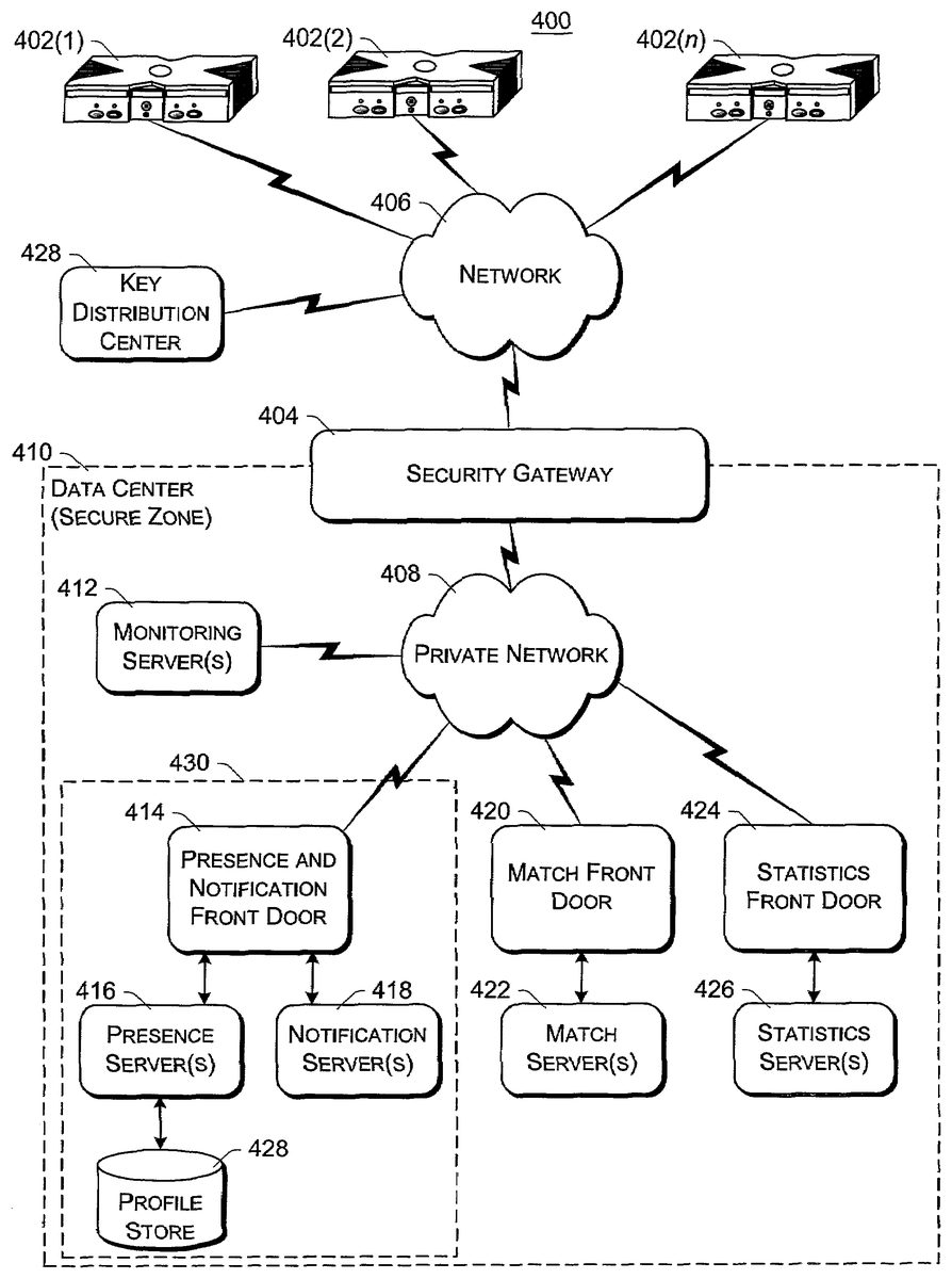
FIG. 7is a block diagram of an exemplary online gaming environment400. Multiple game consoles402(1),402(2), . . . ,402(n) are coupled to a security gateway404via a network406. Each game console402can be, for example, a game console102ofFIG. 1orFIG. 2. Network406represents any one or more of a variety of conventional data communications networks. Network406will typically include packet switched networks, but may also include circuit switched networks. Network406can include wire and/or wireless portions. In one exemplary implementation, network406includes the Internet and may optionally include one or more local area networks (LANs) and/or wide area networks (WANs). At least a part of network406is a public network, which refers to a network that is publicly-accessible. Virtually anyone can access the public network.
In some situations, network406includes a LAN (e.g., a home network), with a routing device situated between game console402and security gateway404. This routing device may perform network address translation (NAT), allowing the multiple devices on the LAN to share the same IP address on the Internet, and also operating as a firewall to protect the device(s) on the LAN from access by malicious or mischievous users via the Internet.
Security gateway404operates as a gateway between public network406and a private network408. Private network408can be any of a wide variety of conventional networks, such as a local area network. Private network408, as well as other devices discussed in more detail below, is within a data center410that operates as a secure zone. Data center410is made up of trusted devices communicating via trusted communications. Thus, encryption and authentication within secure zone410is not necessary. The private nature of network408refers to the restricted accessibility of network408—access to network408is restricted to only certain individuals (e.g., restricted by the owner or operator of data center410).
Security gateway404is a cluster of one or more security gateway computing devices. These security gateway computing devices collectively implement security gateway404. Security gateway404may optionally include one or more conventional load balancing devices that operate to direct requests to be handled by the security gateway computing devices to appropriate ones of those computing devices. This directing or load balancing is performed in a manner that attempts to balance the load on the various security gateway computing devices approximately equally (or alternatively in accordance with some other criteria).
Also within data center410are: one or more monitoring servers412; one or more presence and notification front doors414, one or more presence servers416, one or more notification servers418, and a profile store428(collectively implementing a presence and notification service or system430); one or more match front doors420and one or more match servers422(collectively implementing a match service); and one or more statistics front doors424and one or more statistics servers426(collectively implementing a statistics service). The servers416,418,422, and426provide services to game consoles402, and thus can be referred to as service devices. Other service devices may also be included in addition to, and/or in place of, one or more of the servers416,418,422, and426. Additionally, although only one data center is shown inFIG. 7, alternatively multiple data centers may exist with which game consoles402can communicate. These data centers may operate independently, or alternatively may operate collectively (e.g., to make one large data center available to game consoles102).
Game consoles402are situated remotely from data center410, and access data center410via network406. A game console402desiring to communicate with one or more devices in the data center logs in to the data center and establishes a secure communication channel between the console402and security gateway404. Game console402and security gateway404encrypt and authenticate data packets being passed back and forth, thereby allowing the data packets to be securely transmitted between them without being understood by any other device that may capture or copy the data packets without breaking the encryption. Each data packet communicated from game console402to security gateway404, or from security gateway404to game console402can have data embedded therein. This embedded data is referred to as the content or data content of the packet. Additional information may also be inherently included in the packet based on the packet type (e.g., a heartbeat packet).
The secure communication channel between a console402and security gateway404is based on a security ticket. Console402authenticates itself and the current user(s) of console402to a key distribution center428and obtains, from key distribution center428, a security ticket. Console402then uses this security ticket to establish the secure communication channel with security gateway404. In establishing the secure communication channel with security gateway404, the game console402and security gateway404authenticate themselves to one another and establish a session security key that is known only to that particular game console402and the security gateway404. This session security key is used to encrypt data transferred between the game console402and the security gateway cluster404, so no other devices (including other game consoles402) can read the data. The session security key is also used to authenticate a data packet as being from the security gateway404or game console402that the data packet alleges to be from. Thus, using such session security keys, secure communication channels can be established between the security gateway404and the various game consoles402.
Once the secure communication channel is established between a game console402and the security gateway404, encrypted data packets can be securely transmitted between the two. When the game console402desires to send data to a particular service device in data center410, the game console402encrypts the data and sends it to security gateway404requesting that it be forwarded to the particular service device(s) targeted by the data packet. Security gateway404receives the data packet and, after authenticating and decrypting the data packet, encapsulates the data content of the packet into another message to be sent to the appropriate service via private network408. Security gateway404determines the appropriate service for the message based on the requested service(s) targeted by the data packet.
Similarly, when a service device in data center410desires to communicate data to a game console402, the data center sends a message to security gateway404, via private network408, including the data content to be sent to the game console402as well as an indication of the particular game console402to which i the data content is to be sent. Security gateway404embeds the data content into a data packet, and then encrypts the data packet so it can only be decrypted by the particular game console402and also authenticates the data packet as being from the security gateway404.
Although discussed herein as primarily communicating encrypted data packets between security gateway404and a game console402, alternatively some data packets may be partially encrypted (some portions of the data packets are encrypted while other portions are not encrypted). Which portions of the data packets are encrypted and which are not can vary based on the desires of the designers of data center410and/or game consoles402. For example, the designers may choose to allow voice data to be communicated among consoles402so that users of the consoles402can talk to one another—the designers may further choose to allow the voice data to be unencrypted while any other data in the packets is encrypted. Additionally, in another alternative, some data packets may have no portions that are encrypted (that is, the entire data packet is unencrypted). It should be noted that, even if a data packet is unencrypted or only partially encrypted, all of the data packet can still be authenticated.
Each security gateway device in security gateway404is responsible for the secure communication channel with typically one or more game consoles402, and thus each security gateway device can be viewed as being responsible for managing or handling one or more game consoles. The various security gateway devices may be in communication with each other and communicate messages to a one another. For example, a security gateway device that needs to send a data packet to a game console that it is not responsible for managing may send a message to all the other security gateway devices with the data to be sent to that game console. This message is received by the security gateway device that is responsible for managing that game console and sends the appropriate data to that game console. Alternatively, the security gateway devices may be aware of which game consoles are being handled by which security gateway devices—this may be explicit, such as each security gateway device maintaining a table of game consoles handled by the other security gateway devices, or alternatively implicit, such as determining which security gateway device is responsible for a particular game console based on an identifier of the game console.
Monitoring server(s)412operate to inform devices in data center410of an unavailable game console402or an unavailable security gateway device of security gateway404. Game consoles402can become unavailable for a variety of different reasons, such as a hardware or software failure, the console being powered-down without logging out of data center410, the network connection cable to console402being disconnected from console402, other network problems (e.g., the LAN that the console402is on malfunctioning), etc. Similarly, a security gateway device of security gateway404can become unavailable for a variety of different reasons, such as hardware or software failure, the device being powered-down, the network connection cable to the device being disconnected from the device, other network problems, etc.
Each of the security gateway devices in security gateway404is monitored by one or more monitoring servers412, which detect when one of the security gateway devices becomes unavailable. In the event a security gateway device becomes unavailable, monitoring server412sends a message to each of the other devices in data center410(servers, front doors, etc.) that the security gateway device is no longer available. Each of the other devices can operate based on this information as it sees fit (e.g., it may assume that particular game consoles being managed by the security gateway device are no longer in communication with data center410and perform various clean-up operations accordingly). Alternatively, only certain devices may receive such a message from the monitoring server412(e.g., only those devices that are concerned with whether security gateway devices are available).
Security gateway404monitors the individual game consoles402and detects when one of the game consoles402becomes unavailable. When security gateway404detects that a game console is no longer available, security gateway404sends a message to monitoring server412identifying the unavailable game console. In response, monitoring server412sends a message to each of the other devices in data center410(or alternatively only selected devices) that the game console is no longer available. Each of the other devices can then operate based on this information as it sees fit.
Presence and notification system or service430can be, for example, a system104ofFIG. 1or2. Presence server(s)416hold and process data concerning the status or presence of a given user logged in to data center410for online gaming. Notification server(s)418maintains multiple notification queues of outgoing messages destined for a player logged in to data center410. Presence and notification front door414is one or more server devices that operate as an intermediary between security gateway404and servers416and418. One or more load balancing devices (not shown) may be included in presence and notification front door414to balance the load among the multiple server devices operating as front door414. Security gateway404communicates messages for servers416and418to the front door414, and the front door414identifies which particular server416or particular server418the message is to be communicated to. By using front door414, the actual implementation of servers416and418, such as which servers are responsible for managing data regarding which users, is abstracted from security gateway404. Security gateway404can simply forward messages that target the presence and notification service to presence and notification front door414and rely on front door414to route the messages to the appropriate one of server(s)416and server(s)418.
Match server(s)422hold and process data concerning the matching of online players to one another. An online user is able to advertise a game available for play along with various characteristics of the game (e.g., the location where a football game will be played, whether a game is to be played during the day or at night, the user's skill level, etc.). These various characteristics can then be used as a basis to match up different online users to play games together. Match front door420includes one or more server devices (and optionally a load balancing device(s)) and operates to abstract match server(s)422from security gateway404in a manner analogous to front door414abstracting server(s)416and server(s)418.
Statistics server(s)426hold and process data concerning various statistics for online games. The specific statistics used can vary based on the game designer's desires (e.g., the top ten scores or times, a world ranking for all online players of the game, a list of users who have found the most items or spent the most time playing, etc.). Statistics front door426includes one or more server devices (and optionally a load balancing device(s)) and operates to abstract statistics server(s)426from security gateway404in a manner analogous to front door414abstracting server(s)416and server(s)418.
Thus, it can be seen that security gateway404operates to shield devices in the secure zone of data center410from the untrusted, public network406. Communications within the secure zone of data center410need not be encrypted, as all devices within data center410are trusted. However, any information to be communicated from a device within data center410to a game console402passes through security gateway cluster404, where it is encrypted in such a manner that it can be decrypted by only the game console402targeted by the information.
FIG. 8illustrates a general computer environment500, which can be used to implement the techniques described herein. The computer environment500is only one example of a computing environment and is not intended to suggest any limitation as to the scope of use or functionality of the computer and network architectures. Neither should the computer environment500be interpreted as having any dependency or requirement relating to any one or combination of components illustrated in the exemplary computer environment500.
Computer environment500includes a general-purpose computing device in the form of a computer502. Computer502can be, for example, a presence and notification system104ofFIG. 1, a presence server120ofFIG. 2, a notification server122ofFIG. 2, a profile store ofFIG. 2, a security gateway404ofFIG. 7, a server412,416,418,422, and/or426ofFIG. 7, a profile store428ofFIG. 7, or a front door414,420, or424ofFIG. 7. The components of computer502can include, but are not limited to, one or more processors or processing units504(optionally including a cryptographic processor or co-processor), a system memory506, and a system bus508that couples various system components including the processor504to the system memory506.
The system bus508represents one or more of any of several types of bus structures, including a memory bus or memory controller, a peripheral bus, an accelerated graphics port, and a processor or local bus using any of a variety of bus architectures. By way of example, such architectures can include an Industry Standard Architecture (ISA) bus, a Micro Channel Architecture (MCA) bus, an Enhanced ISA (EISA) bus, a Video Electronics Standards Association (VESA) local bus, and a Peripheral Component Interconnects (PCI) bus also known as a Mezzanine bus.
Computer502typically includes a variety of computer readable media. Such media can be any available media that is accessible by computer502and includes both volatile and non-volatile media, removable and non-removable media.
The system memory506includes computer readable media in the form of volatile memory, such as random access memory (RAM)510, and/or non-volatile memory, such as read only memory (ROM)512. A basic input/output system (BIOS)514, containing the basic routines that help to transfer information between elements within computer502, such as during start-up, is stored in ROM512. RAM510typically contains data and/or program modules that are immediately accessible to and/or presently operated on by the processing unit504.
Computer502may also include other removable/non-removable, volatile/non-volatile computer storage media. By way of example,FIG. 7illustrates a hard disk drive516for reading from and writing to a non-removable, non-volatile magnetic media (not shown), a magnetic disk drive518for reading from and writing to a removable, non-volatile magnetic disk520(e.g., a “floppy disk”), and an optical disk drive522for reading from and/or writing to a removable, non-volatile optical disk524such as a CD-ROM, DVD-ROM, or other optical media. The hard disk drive516, magnetic disk drive518, and optical disk drive522are each connected to the system bus508by one or more data media interfaces526. Alternatively, the hard disk drive516, magnetic disk drive518, and optical disk drive522can be connected to the system bus508by one or more interfaces (not shown).
The disk drives and their associated computer-readable media provide non-volatile storage of computer readable instructions, data structures, program modules, and other data for computer502. Although the example illustrates a hard disk516, a removable magnetic disk520, and a removable optical disk524, it is to be appreciated that other types of computer readable media which can store data that is accessible by a computer, such as magnetic cassettes or other magnetic storage devices, flash memory cards, CD-ROM, digital versatile disks (DVD) or other optical storage, random access memories (RAM), read only memories (ROM), electrically erasable programmable read-only memory (EEPROM), and the like, can also be utilized to implement the exemplary computing system and environment.
Any number of program modules can be stored on the hard disk516, magnetic disk520, optical disk524, ROM512, and/or RAM510, including by way of example, an operating system526, one or more application programs528, other program modules530, and program data532. Each of such operating system526, one or more application programs528, other program modules530, and program data532(or some combination thereof) may implement all or part of the resident components that support the distributed file system.
A user can enter commands and information into computer502via input devices such as a keyboard534and a pointing device536(e.g., a “mouse”). Other input devices538(not shown specifically) may include a microphone, joystick, game pad, satellite dish, serial port, scanner, and/or the like. These and other input devices are connected to the processing unit504via input/output is interfaces540that are coupled to the system bus508, but may be connected by other interface and bus structures, such as a parallel port, game port, or a universal serial bus (USB).
A monitor542or other type of display device can also be connected to the system bus508via an interface, such as a video adapter544. In addition to the monitor542, other output peripheral devices can include components such as speakers (not shown) and a printer546which can be connected to computer502via the input/output interfaces540.
Computer502can operate in a networked environment using logical connections to one or more remote computers, such as a remote computing device548. By way of example, the remote computing device548can be a personal computer, portable computer, a server, a router, a network computer, a peer device or other common network node, game console, and the like. The remote computing device548is illustrated as a portable computer that can include many or all of the elements and features described herein relative to computer502.
Logical connections between computer502and the remote computer548are depicted as a local area network (LAN)550and a general wide area network (WAN)552. Such networking environments are commonplace in offices, enterprise-wide computer networks, intranets, and the Internet.
When implemented in a LAN networking environment, the computer502is connected to a local network550via a network interface or adapter554. When implemented in a WAN networking environment, the computer502typically includes a modem556or other means for establishing communications over the wide network552. The modem556, which can be internal or external to computer502, can be connected to the system bus508via the input/output interfaces540or other appropriate mechanisms. It is to be appreciated that the illustrated network connections are exemplary and that other means of establishing communication link(s) between the computers502and548can be employed.
In a networked environment, such as that illustrated with computing environment500, program modules depicted relative to the computer502, or portions thereof, may be stored in a remote memory storage device. By way of example, remote application programs558reside on a memory device of remote computer548. For purposes of illustration, application programs and other executable program components such as the operating system are illustrated herein as discrete blocks, although it is recognized that such programs and components reside at various times in different storage components of the computing device502, and are executed by the data processor(s) of the computer.
Various modules and techniques may be described herein in the general context of computer-executable instructions, such as program modules, executed by one or more computers or other devices. Generally, program modules include routines, programs, objects, components, data structures, etc. that perform particular tasks or implement particular abstract data types. Typically, the functionality of the program modules may be combined or distributed as desired in various embodiments.
An implementation of these modules and techniques may be stored on or transmitted across some form of computer readable media. Computer readable media can be any available media that can be accessed by a computer. By way of example, and not limitation, computer readable media may comprise “computer storage media” and “communications media.”
“Computer storage media” includes volatile and non-volatile, removable and non-removable media implemented in any method or technology for storage of information such as computer readable instructions, data structures, program modules, or other data. Computer storage media includes, but is not limited to, RAM, ROM, EEPROM, flash memory or other memory technology, CD-ROM, digital versatile disks (DVD) or other optical storage, magnetic cassettes, magnetic tape, magnetic disk storage or other magnetic storage devices, or any other medium which can be used to store the desired information and which can be accessed by a computer.
“Communication media” typically embodies computer readable instructions, data structures, program modules, or other data in a modulated data signal, such as carrier wave or other transport mechanism. Communication media also includes any information delivery media. The term “modulated data signal” means a signal that has one or more of its characteristics set or changed in such a manner as to encode information in the signal. By way of example, and not limitation, communication media includes wired media such as a wired network or direct-wired connection, and wireless media such as acoustic, RF, infrared, and other wireless media. Combinations of any of the above are also included within the scope of computer readable media.
FIG. 9shows functional components of a game console102in more detail. Game console102has a central processing unit (CPU)600and a memory controller602that facilitates processor access to various types of memory, including a flash ROM (Read Only Memory)604, a RAM (Random Access Memory)606, a hard disk drive608, and a portable media drive609. CPU600is equipped with a level 1 cache610and a level 2 cache612to temporarily store data and hence reduce the number of memory access cycles, thereby improving processing speed and throughput.
CPU600, memory controller602, and various memory devices are interconnected via one or more buses, including serial and parallel buses, a memory bus, a peripheral bus, and a processor or local bus using any of a variety of bus architectures. By way of example, such architectures can include an Industry Standard Architecture (ISA) bus, a Micro Channel Architecture (MCA) bus, an Enhanced ISA (EISA) bus, a Video Electronics Standards Association (VESA) local bus, and a Peripheral Component Interconnects (PCI) bus also known as a Mezzanine bus.
As one suitable implementation, CPU600, memory controller602, ROM604, and RAM606are integrated onto a common module614. In this implementation, ROM604is configured as a flash ROM that is connected to the memory controller602via a PCI (Peripheral Component Interconnect) bus and a ROM bus (neither of which are shown). RAM606is configured as multiple DDR SDRAM (Double Data Rate Synchronous Dynamic RAM) that are independently controlled by the memory controller602via separate buses (not shown). The hard disk drive608and portable media drive609are connected to the memory controller via the PCI bus and an ATA (AT Attachment) bus616.
A 3D graphics processing unit620and a video encoder622form a video processing pipeline for high speed and high resolution graphics processing. Data is carried from the graphics processing unit620to the video encoder622via a digital video bus (not shown). An audio processing unit624and an audio codec (coder/decoder)626form a corresponding audio processing pipeline with high fidelity and stereo processing. Audio data is carried between the audio processing unit624and the audio codec626via a communication link (not shown). The video and audio processing pipelines output data to an A/V (audio/video) port628for transmission to the television or other display. In the illustrated implementation, the video and audio processing components620-628are mounted on the module614.
Also implemented on the module614are a USB host controller630and a network interface632. The USB host controller630is coupled to the CPU600and the memory controller602via a bus (e.g., PCI bus) and serves as host for the peripheral controllers636(1)-636(4). The network interface632provides access to a network (e.g., Internet, home network, etc.) and may be any of a wide variety of various wire or wireless interface components including an Ethernet card, a modem, a Bluetooth module, a cable modem, and the like.
The game console102has two dual controller support subassemblies640(1) and640(2), with each subassembly supporting two game controllers636(1)-636(4). A front panel I/O subassembly642supports the functionality of a power button631and a media drive eject button633, as well as any LEDs (light emitting diodes) or other indicators exposed on the outer surface of the game console. The subassemblies640(1),640(2), and642are coupled to the module614via one or more cable assemblies644.
Eight memory units634(1)-634(8) are illustrated as being connectable to the four controllers636(1)-636(4), i.e., two memory units for each controller. Each memory unit634offers additional storage on which games, game parameters, and other data may be stored. When inserted into a controller, the memory unit634can be accessed by the memory controller602.
A system power supply module650provides power to the components of the game console102. A fan652cools the circuitry within the game console102.
A console user interface (UI) application660is stored on the hard disk drive608. When the game console is powered on, various portions of the console application660are loaded into RAM606and/or caches610,612and executed on the CPU600. Console application660presents a graphical user interface that provides a consistent user experience when navigating to different media types available on the game console.
Game console102implements a cryptography engine to perform common cryptographic functions, such as encryption, decryption, authentication, digital signing, hashing, and the like. The cryptography engine may be implemented as part of the CPU600, or in software stored on the hard disk drive608that executes on the CPU, so that the CPU is configured to perform the cryptographic functions. Alternatively, a cryptographic processor or co-processor designed to perform the cryptographic functions may be included in game console102.
Game console102may be operated as a standalone system by simply connecting the system to a television or other display. In this standalone mode, game console102allows one or more players to play games, watch movies, or listen to music. However, with the integration of broadband connectivity made available through the network interface632, game console102may further be operated as a participant in online gaming, as discussed above.
In the discussions herein, a significant amount of functionality is provided by presence and notification system104. In alternate embodiments, this functionality, or portions of this functionality, may be provided by one or more of the game consoles102.
Although the description above uses language that is specific to structural features and/or methodological acts, it is to be understood that the invention defined in the appended claims is not limited to the specific features or acts described. Rather, the specific features and acts are disclosed as exemplary forms of implementing the invention.
Claims
- A method, comprising: loading, by a computing device, when a first user logs in to a system, persistent data for the user from a profile store;identifying, by the computing device, from the persistent data, one or more friends of the first user, the persistent data including a list of second users that the first user never wants to be friends with;identifying, by the computing device, based on an identifier associated with the first user, which of a plurality of notification servers to load the persistent data to;establishing, by the computing device, at least one notification queue for the first user;checking, by the computing device, whether any information in the profile store is to be added to the at least one notification queue;adding, by the computing device, based on the checking, information to the at least one notification queue;facilitating, by the computing device, the first user in adding a third user to the list;receiving, by the computing device, a friend invitation from the third user;sending, by the computing device, to the third user a response message to the friend invitation without notifying the first user of receipt of the friend invitation and without notifying the first user of the response message, the response message indicating that the first user has rejected the friend invitation;checking, by the computing device, whether each of the one or more friends is logged in to the system;for each of the one or more friends that is logged in to the system, subscribing, by the computing device, the first user to the friend's information and subscribing each friend to the first user's information;facilitating, by the computing device, the first user in sending a friend invitation to one of the second users or the third user;and in response to sending the friend invitation, removing, by the computing device, the invited second user or third user from the list of second users that the first user never wants to be friend with.
- A method as recited in claim 1 , further comprising: identifying, based on an identifier associated with the first user, which of a plurality of presence servers to load the persistent data to.
- A method as recited in claim 2 , wherein the identifier comprises a 64-bit user identifier.
- A method as recited in claim 2 , wherein the identifier is based at least in part on a game title identifier.
- A method as recited in claim 2 , wherein the identifier is based at least in part on a game manufacturer identifier.
- A method as recited in claim 1 , wherein the identifier comprises a 64-bit user identifier.
- A method as recited in claim 1 , wherein the identifier is based at least in part on a game title identifier.
- A method as recited in claim 1 , wherein the identifier is based at least in part on a game manufacturer identifier.
- A method as recited in claim 1 , wherein the persistent data includes a list of one or more other users that are friends of the first user.
- A method as recited in claim 1 , wherein the persistent data includes a list of one or more other users that the first user has requested to mute.
- A method as recited in claim 1 , further comprising: establishing user information regarding the current login session of the first user.
- A method as recited in claim 11 , wherein the information regarding the current login session of the first user comprises a game title currently being played by the first user.
- A method as recited in claim 11 , wherein the information regarding the current login session of the first user comprises a fully qualified address of the first user.
- A method as recited in claim 11 , wherein the information regarding the current login session of the first user comprises security information a game session being played by the first user.
- A method as recited in claim 11 , wherein the information regarding the current login session of the first user comprises a current status of the first user.
- The method of claim 1 , further comprising allowing the first user to temporarily mute another user.
- A system comprising: a plurality of notification servers;and a processor, the processor executing a plurality of programming instructions that perform the following operations: loading, to one of the plurality of notification servers and when a first user logs in to a system, persistent data for the user from a profile store;identifying, from the persistent data, one or more friends of the first user, the persistent data including both a list of second users that the first user never wants to be friends with and a list of one or more other users that the first user has requested to mute;facilitating the first user in adding a third user to the list;receiving a friend invitation from the third user;sending to the third user a response message to the friend invitation without notifying the first user of receipt of the friend invitation and without notifying the first user of the response message, the response message indicating that the first user has rejected the friend invitation;checking whether each of the one or more friends is logged in to the system;for each of the one or more friends that is logged in to the system, subscribing the first user to the friend's information and subscribing each friend to the first user's information;facilitating the first user in sending a friend invitation to one of the second users or the third user;and in response to sending the friend invitation, removing the invited second user or third user from the list of second users that the first user never wants to be friends with.
- A system as recited in claim 17 , wherein the instructions, when executed by the processor further perform operations including: loading, when the first user logs in to the system, a list of friends of the first user;checking whether each of the one or more friends is logged in to the system;and for each of the one or more friends that is logged in to the system, adding the friend to the subscription list and adding the first user to the other subscription list corresponding to the first friend.
- A method, comprising: loading, by a computing device, when a first user logs in to a system, persistent data for the user from a profile store;identifying, by the computing device, from the persistent data, one or more friends of the first user, the persistent data including a list of second users that the first user never wants to be friends with;facilitating, by the computing device, the first user in adding a third user to the list;receiving, by the computing device, a friend invitation from the third user;sending, by the computing device, to the third user a response message to the friend invitation without notifying the first user of receipt of the friend invitation and without notifying the first user of the response message, the response message indicating that the first user has rejected the friend invitation;checking, by the computing device, whether each of the one or more friends is logged in to the system;for each of the one or more friends that is logged in to the system, subscribing, by the computing device, the first user to the friend's information and subscribing each friend to the first user's information;establishing, by the computing device, at least one notification queue for the user;checking, by the computing device, whether any information in the profile store is to be added to the at least one notification queue;and adding, by the computing device, based on the checking, information to the at least one notification queue;establishing, by the computing device, user information regarding the current login session of the first user;facilitating, by the computing device, the first user in sending a friend invitation to one of the second users or the third user;and in response to sending the friend invitation, removing, by the computing device, the invited second user or third user from the list of second users that the first user never wants to be friends with.
Disclaimer: Data collected from the USPTO and may be malformed, incomplete, and/or otherwise inaccurate.