U.S. Pat. No. 7,637,817
INFORMATION PROCESSING DEVICE, GAME DEVICE, IMAGE GENERATION METHOD, AND GAME IMAGE GENERATION METHOD
AssigneeSega
Issue DateDecember 22, 2004
U.S. Patent No. 7,637,817: Information processing device, game device, image generation method, and game image generation method

Summary:
The ‘817 patent describes a method of playing a game with a gun-like controller which uses infrared light to accurately reflect the player’s movements by using detectable waves. The controller allows the player to move around in a three-dimensional world and have his movements accurately mapped out on the screen. Whenever a person locks the target onto an object, the screen will change to give the player the optimal view point.
Abstract:
Provided is technology enabling the generation of images of high realistic sensation upon accurately reflecting the operator’s behavior. The information processing device has a controller to be used for inputting an operational instruction, and having a function of outputting a detectable wave to be used for detecting its own position and direction; a plurality of sensors for detecting the intensity of the detectable wave transmitted from the controller at mutually different positions; a position/direction calculation unit for calculating the position and direction of the controller in a real space based on the ratio of the intensity of the detectable wave detected with each of the plurality of sensors; an image generation unit for generating an image reflecting the operational instruction input with the controller, and the position and direction of the controller calculated with the position/direction calculation unit; and a display unit for displaying the image generated with the image generation unit.
Illustrative Claim:
1. A simulation apparatus, comprising: an information processing device; a monitor display connected to said information processing device; operational means connected to said information processing device, configured to be operable by a player and having radiation means which radiates a detectable wave expanding toward said monitor display; and a plurality of detection means disposed at mutually different positions along peripheries of said monitor display, each of said detection means being configured to detect intensity components of said detectable wave in three-dimensional directions; wherein said information processing device comprises calculation means which calculates positional coordinates of said operational means in a real space in front of said monitor display and an aiming direction of said operational means based on ratios of the intensity components of said detectable wave detected by said plurality of detection means at said different positions, wherein said information processing device is configured to: (a) calculate a scene including a first object and a second object in a virtual three-dimensional space; (b) display on the monitor display the scene viewed from a virtual viewpoint wherein said first object is located behind said second object when viewed from said virtual viewpoint in the virtual three-dimensional space; (c) convert, while the virtual viewpoint remains as set in (b), the calculated positional coordinates and the calculated aiming direction of said operational means in the real space into positional coordinates and an aiming direction in the virtual three-dimensional space so that a position of a virtual shooting point aiming at said first object along the aiming direction is set off the virtual viewpoint, which is set at the location as in (b), in the virtual three-dimensional space; and (d) determine if the converted aiming direction extending from said shooting point hits said first object.
Illustrative Figure
Abstract
Provided is technology enabling the generation of images of high realistic sensation upon accurately reflecting the operator's behavior. The information processing device has a controller to be used for inputting an operational instruction, and having a function of outputting a detectable wave to be used for detecting its own position and direction; a plurality of sensors for detecting the intensity of the detectable wave transmitted from the controller at mutually different positions; a position/direction calculation unit for calculating the position and direction of the controller in a real space based on the ratio of the intensity of the detectable wave detected with each of the plurality of sensors; an image generation unit for generating an image reflecting the operational instruction input with the controller, and the position and direction of the controller calculated with the position/direction calculation unit; and a display unit for displaying the image generated with the image generation unit.
Description
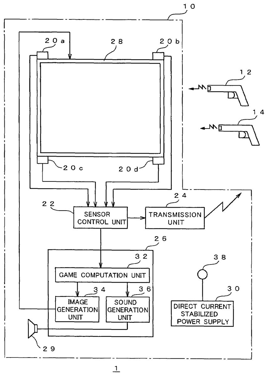
DETAILED DESCRIPTION OF THE PREFERRED EMBODIMENTS Embodiments of the present invention are now explained with reference to the drawings. FIG. 1is a diagram for explaining the constitution of the game device according to an embodiment employing the present invention. The game device1shown inFIG. 1is for up to two players (operators) to simultaneously play a shooting game while watching the game image displayed three-dimensionally on the screen, and is constituted by including a game device body10and two gun-shaped controllers12,14. The gun-shaped controllers12,14are operational means having a shape imitating the appearance of various types of guns (e.g., machine gun, pistol, rifle, shotgun, laser gun, etc.). The gun-shaped controller12is for a first player to input operations, and the gun-shaped controller14is for a second player to input operations. These gun-shaped controllers12,14are wireless in which a connection cable is not provided between the game device body10, and the player is able to freely operate such [controller] without being subject to any restraints regarding the operational area normally encountered with a connection cable. The transfer of signals and the like between the game device body10and the respective gun-shaped controllers12,14is conducted via wireless communication. Incidentally, details on the constitution of the gun-shaped controllers12,14will be described later. The game device body10is constituted by including a plurality of sensors20ato20d, a sensor control unit22, a transmission unit24, a game control unit26, a monitor28, and a direct current stabilized power supply30. Each of the respective sensors20ato20dis disposed in the vicinity of the four corners of the screen of a monitor28, detects the intensity of the detectable wave transmitted from one of the gun-shaped controllers12,14, and outputs the detection result to the sensor control unit22. The respective sensors20ato20din the present embodiment have sensor planes (detector planes) disposed toward three mutually different directions. Details regarding the disposition of the sensors20ato20dwill be described later. ...
DETAILED DESCRIPTION OF THE PREFERRED EMBODIMENTS
Embodiments of the present invention are now explained with reference to the drawings.
FIG. 1is a diagram for explaining the constitution of the game device according to an embodiment employing the present invention. The game device1shown inFIG. 1is for up to two players (operators) to simultaneously play a shooting game while watching the game image displayed three-dimensionally on the screen, and is constituted by including a game device body10and two gun-shaped controllers12,14.
The gun-shaped controllers12,14are operational means having a shape imitating the appearance of various types of guns (e.g., machine gun, pistol, rifle, shotgun, laser gun, etc.). The gun-shaped controller12is for a first player to input operations, and the gun-shaped controller14is for a second player to input operations. These gun-shaped controllers12,14are wireless in which a connection cable is not provided between the game device body10, and the player is able to freely operate such [controller] without being subject to any restraints regarding the operational area normally encountered with a connection cable. The transfer of signals and the like between the game device body10and the respective gun-shaped controllers12,14is conducted via wireless communication. Incidentally, details on the constitution of the gun-shaped controllers12,14will be described later.
The game device body10is constituted by including a plurality of sensors20ato20d, a sensor control unit22, a transmission unit24, a game control unit26, a monitor28, and a direct current stabilized power supply30.
Each of the respective sensors20ato20dis disposed in the vicinity of the four corners of the screen of a monitor28, detects the intensity of the detectable wave transmitted from one of the gun-shaped controllers12,14, and outputs the detection result to the sensor control unit22. The respective sensors20ato20din the present embodiment have sensor planes (detector planes) disposed toward three mutually different directions. Details regarding the disposition of the sensors20ato20dwill be described later. These sensors20ato20dcorrespond to the “detection means”.
The sensor control unit22calculates the position and direction of the gun-shaped controller12or14in the space based on the ratio of the intensity of the detectable wave detected respectively with the plurality of sensors20ato20d. Details regarding the calculation method of the position and direction with the sensor control unit22will be described later. Further, the sensor control unit22uses the transmission unit24to select one among the respective gun-shaped controllers12,14in each prescribed timing, and transmits a prescribed identifying signal representing the selected gun-shaped controller. This identifying signal is transmitted with the transmission unit24via wireless communication. Each of the gun-shaped controllers12,14transmits a detectable wave only when it is being selected based on the identifying signal. This sensor control unit22and each of the foregoing sensors20ato20dcollaborate and function as the “position detection means” and “orientation direction means”.
The game control unit26sets the game progress and generates a game image in correspondence with the content of the operational instruction input with the gun-shaped controllers12,14, and the position and direction of such gun-shaped controllers12,14, and contains the respective functional blocks of the game computation unit32, image generation unit34and sound generation unit36. Incidentally, this game control unit26corresponds to the “image generation means”.
The game computation unit32is used for performing the various computations required in the game progress, and performs processing for setting the behavior of various objects (e.g., enemy character and the like) in the virtual space upon reflecting the operational instruction input with the gun-shaped controllers12,14and the position and direction of the gun-shaped controllers12,14calculated with the sensor control unit22.
The image generation unit34generates a two-dimensional image (game image) viewed from a virtual viewpoint in the game space in correspondence with the computation result of the game computation unit32.
The sound generation unit36generates various game sounds (e.g., explosion sounds and background music) required for the game progress in correspondence with the computation result of the game computation unit32.
The monitor28displays the game image generated with the image generation unit34on a screen. Moreover, the monitor28has a built-in speaker not shown, and outputs the game sound generated with the sound generation unit36. This monitor28corresponds to the “display means”.
The direct current stabilized power supply30supplies power to the overall game device body10, and charges the respective gun-shaped controllers12,14via a charging terminal38.
FIG. 2is a diagram for explaining a specific example of the hardware constitution that realizes the game control unit. The game control unit26shown inFIG. 2is constituted by including an input interface100, a CPU101, a ROM102, a work RAM103, a video processor104, a video memory105, a digital/analog (D/A) converters106, a sound processor107, and a sound memory108.
The input interface100receives information regarding the position and direction of, and the firing of bullets from, the respective gun-shaped controllers12,14from the sensor control unit22, and writes such information (data) in a prescribed address of the work RAM103.
The CPU101executes the game program read out from the ROM102and written into the work RAM103, and performs game computation for setting the game progress and so on. Moreover, the CPU101determines the coordinate value (coordinate value in the world coordinate system) of an object such as the various characters or structures in the game space according to the set game progress, and performs processing (projection conversion) for projecting this coordinate value in the coordinate value in a visual field coordinate system with a prescribed conversion matrix.
The ROM102stores the foregoing game program and various data (e.g., polygon data, texture data, etc.) used in the game computation. The work RAM103is a random access memory that functions as a work area for temporarily storing various data upon the CPU101performing game computation.
The video processor104laminates texture to the various objects converted into a visual field coordinate system and generates drawing data corresponding to the game image to be displayed in the subsequent frame, and writes this in the video memory105. Further, the video processor104reads the drawing data corresponding to the game image to be displayed in the current frame and outputs this to the D/A converter106. As a result of this drawing data being converted into an analog video signal with the D/A converter106and output to the monitor28, a game image is displayed on the screen of the monitor28.
The sound processor107generates sound data for providing sound effects corresponding to the game progress and writes this into the sound memory108, and further reads sound data from the sound memory108as required and converts such sound data into an analog sound signal, and outputs this to the speaker29. Game sound is output from the speaker29based on the foregoing sound signal.
FIG. 3is a diagram for explaining the detailed constitution of the gun-shaped controller12. Incidentally, the gun-shaped controller14has the same constitution, and the explanation thereof is omitted. As shown inFIG. 3, the gun-shaped controller12has an operational unit40, a light emission unit42, a light emission control unit44, a power supply/charging circuit46, and a battery48.
The operational unit40is used as the operational key (trigger switch) for the player to instruct the firing of bullets. Incidentally, as the operational unit40, in addition to the operational key as the trigger switch, also employed may be a switch for instructing the change of weapons (weapon changing switch), a bullet loading switch (reloading switch), or the like.
The light emission unit42is disposed at the front part of the case of the gun-shaped controller12; specifically, near the muzzle thereof, so as to enable the outward transmission of the detectable wave, and, upon being controlled with the light emission control unit44, transmits the detectable wave. In the present embodiment, infrared light is used to transmit the detectable wave. Incidentally, in addition to infrared light, electromagnetic waves of various wavelengths such as visible light, or sound waves, may be used to transmit the detectable wave.
The light emission control unit44controls the operation of the light emission unit42. Description of the specific control will be explained later. This light emission control unit44corresponds to the “detectable wave control unit”.
The power supply/charging circuit46has a power supply circuit for supplying power to the overall gun-shaped controller12with the power accumulated in the battery48, and a charging circuit for charging the battery48upon being externally supplied with power via the charging terminal50.
The game device1of the present embodiment has the foregoing constitution, and the description of its operation is explained below.
FIG. 4(A) andFIG. 4(B) are diagrams for explaining the calculation method of the position and direction of the gun-shaped controller.FIG. 4(A) shows the spatial positional relationship of the gun-shaped controller and the respective sensors20ato20d, andFIG. 4(B) shows the definition of the vector representing the direction of the gun-shaped controller.
As shown inFIG. 4, each of the sensors20ato20dis disposed in the vicinity of the four corners of a screen28aof the monitor28. In detail, the sensor20ais disposed at the upper left of the screen28a, the sensor20bis disposed at the upper right of the screen28a, the sensor20cis provided at the lower left of the screen28a, and the sensor20dis disposed at the lower right of the screen28a. In this example, basically, the area surrounded by these sensors20ato20dwill be the detection area. This detection area is the area to be aimed with the gun-shaped controller12. Although this will also depend on the sensitivity of each sensor, the area in which the respective sensors are able to detect the detectable wave transmitted from the gun-shaped controller12shall be an area that is wider than the foregoing detection area.
The respective sensors20ato20dhave three sensor planes disposed toward mutually different directions, and these three sensor planes are respectively facing the X direction (horizontal direction), Y direction (vertical direction), and Z direction (depth direction). Each of the sensors20ato20ddetects, with the three sensor planes, the intensity (amount of entering infrared light in this example) of the detectable signal in the X, Y, Z directions transmitted from the light emission unit42of the gun-shaped controller12(or14).
The sensor control unit22seeks the three-dimensional direction vector representing the position of the gun-shaped controller12, with the disposed position of each sensor20ato20das the basic point, based on the ratio of the amount of entering light in the X, Y, Z directions of the respective sensors20ato20d. As shown inFIG. 4, the direction vector va corresponding to the sensor20a, the direction vector vb corresponding to the sensor20b, the direction vector vc corresponding to the sensor20c, and the direction vector vd corresponding to the sensor20dare respectively sought. As a result of synthesizing these direction vectors va, vb, vc and vd, the position of the controller can be obtained as a three-dimensional coordinate value (x, y, z). Further, the direction of the controller is obtained as two angles; namely, angle θ formed with the XZ plane, and angle φ formed with the XY plane.
Here, so as long as the direction vector with sensors in at least two locations as the basic point are known, the position of the gun-shaped controller12(or14) can be known. Moreover, when the light emission unit42of the gun-shaped controller12emits light at an arbitrary position toward an arbitrary direction, the ratio of the amount of entering light in each sensor20ato20dwill be determined uniquely. Therefore, the sensor control unit22calculates the direction to which the gun-shaped controller12is facing based on the ratio of the amount of entering light in relation to the respective sensors20ato20d. Incidentally, although the direction of the gun-shaped controller12may be suitably defined, for instance, it would be desirable to make it correspond to the direction of the barrel of the gun.
When the position and direction of the gun-shaped controller12are calculated as described above, it will be possible to determine where on the screen and from what angle the player using the gun-shaped controller12is aiming, and the distance of the player (far or near) to the screen can also be determined. Therefore, the position of the gun-shaped controller12(i.e., position of the player) can be converted into a position in the game space to determine the relative positional relationship (distance, direction) with the object existing in such game space, and various game presentations can be made upon utilizing such determination result.
Next, the operational procedure for calculating the position and direction of the respective gun-shaped controllers is explained.
FIG. 5is a flowchart for explaining the operation of calculating the position and direction as well as determining the contents of the operational instructions of each gun-shaped controller.
The sensor control unit22selects one controller among the respective gun-shaped controllers12,14in each prescribed timing (e.g., each 0.1 second), and transmits an identifying signal for identifying the selected controller via the transmission unit24(step S100).
The light emission control unit44provided to each gun-shaped controller12,14receives the identifying signal via the reception antenna45, determines whether its own gun-shaped controller is being selected based on the identifying signal, and, when one's own controller is being selected, makes the light emission unit42output a detectable wave. As a result, only one gun-shaped controller that was selected (selected controller) will transmit the detectable wave (step S102). For example, an explanation of the selected controller being the gun-shaped controller12is provided below. With the present embodiment, since the respective controllers will not have to constantly emit light, it will be possible to suppress the power consumption since the emission of light is only required upon becoming a selected controller, and the life of the battery48can be prolonged. Further, since only one controller will be selected and emit light in a certain timing, it will be possible to suppress the emission of light that will generate noise.
Moreover, in parallel with the operation shown at step S102, the light emission control unit44of the gun-shaped controller12, which is the selected controller, control is performed for changing the state of the detectable wave output from the light emission unit42according to the content of the operational instruction (operational state of the trigger switch40in this example) (step S104). For instance, in the present embodiment, control for making the detectable wave flash as a pulse is performed, and the content of the operational instruction is overlapped with the detectable wave by varying this flashing state and expressing a digital signal (serial signal).
When the detectable wave is transmitted from the gun-shaped controller12(selected controller), the intensity thereof is detected with the respective sensors20ato20d(step S106). The sensor control unit22calculates the position and direction of the gun-shaped controller12(selected controller) based on the intensity of the detectable wave detected with each of the sensors20ato20d(step S108). The specific calculation method is as described above (c.f.FIG. 4).
Moreover, the sensor control unit22determines the content of the operational instruction overlapped with the detectable wave based on the state of the detectable wave detected with each of the sensors20ato20d(step S110). As described above, in this example, since the digital signal is expressed with the state of the detectable wave, the content of the operational instruction is determined pursuant to the content of this digital signal. Incidentally, with respect to the detection result of the respective sensors20ato20d, for instance, it is also preferable to extract three detection results in the order from the strongest signal intensity, and subjecting these to processing such as comparing the content of the digital signals to be determined based on these detection result and taking a majority vote so as to improve the determination accuracy of the content of the operational instruction. The calculation result of the position and direction of the gun-shaped controller12(selected controller) and the content of the operational instruction obtained as described above are output from the sensor control unit22to the game computation unit32. And, the routine returns to step S100described above, and the subsequent processing steps are repeated.
Next, the operational procedures of the game control unit26to be conducted in parallel with the processing depicted inFIG. 5described above are explained.
FIG. 6is a flowchart showing the operational procedure of the game control unit. The series of processing steps shown inFIG. 6are repeated, for instance, every 1/60 seconds in correspondence with the generation timing of the game image.
The game computation unit32in the game control unit26acquires the position and direction of the respective gun-shaped controllers12,14, as well as the information regarding the content of the operational instruction (step S200). Specifically, a flag (data) showing the calculation result of the sensor control unit22is written into the work RAM103(c.f.FIG. 2) as needed, and information regarding the position and the like of each controller can be acquired by referring to this flag.
Next, the game computation unit26performs prescribed game computation such as setting the state of each object disposed in the game space by using information regarding the position and the like of the respective gun-shaped controllers (step S202). In the present embodiment, as a result of obtaining the position and direction of the respective gun-shaped controllers, various game presentations that were not possible conventionally are enabled. Specific examples of the game presentation will be described later.
When prescribed game computation is performed with the game computation unit26, in accordance with such computation result, a game image is generated with the image generation unit34, and game sound is generated with the sound generation unit36(step S204). As a result of such game image and game sound being sent to the monitor28, a game image is displayed, and game sound is output (step S206).
Further, the game computation unit26determines whether it is game over (step S208). When it is not game over, an affirmative judgment is made at step S208, the routine returns to step S200described above, and the subsequent processing steps are repeated. In addition, when it is game over, the game computation unit26ends the series of processing steps.
FIG. 7is a flowchart showing a specific example of the processing performed at step [S]202described above. For example, the processing routine in a case of shooting down an enemy object with the gun-shaped controller is exemplified.
Foremost, the game computation unit32calculates the position on the screen28ato which the gun-shaped controller12is aiming and the direction (orientation) of the vector heading from the gun-shaped controller12to such position based on the detection result of the position (firing point) and direction of the gun-shaped controller in the real space of the with the monitor28as the reference (step S300). Specifically, the firing point on the screen is calculated with the two-dimensional coordinates with a prescribed position (upper left corner for example) of the screen28aas the reference, and the angles θ and φ obtained at step S200are used for the direction of the vector.
Next, the game computation unit32converts the firing point on the screen28ainto the firing point in the virtual space, and calculates the vector headed from the converted firing point into the virtual space (step S302). Here, when the gun-shaped controller12is facing straight at the screen28a; in other words, when it is disposed in a direction that is approximately orthogonal thereto, the position of the firing point on the screen28amay be set to be the center of the screen.
Next, the game computation unit32determines whether the operator pulled the trigger based on the content of the operational instruction acquired at step S200(step S304). When the trigger has not been pulled, a negative judgment is made, and the processing routine of this example is ended.
Further, when the trigger has been pulled, an affirmative judgment is made at step S304, and the game computation unit32judges whether the aim is on the target object such as an enemy character (step S306). Specifically, the game computation unit32makes the judgment at step S306by searching whether the target object exists on the extension of the vector direction from the firing point in the virtual space.
When the aim is on the target object, an affirmative judgment is made at step S306, and the game computation unit32sets the impact point coordinates at the intersection point of the vector direction from the firing point and the target object in the virtual space (step S308). When this kind of game computation is performed, after the processing routine of this example is ended, an image expressing the target object such as an enemy character being hit and the corresponding reaction (e.g., injury, destruction, etc.) is generated and displayed.
Moreover, when the aim is not on the target object, a negative judgment is made at step S306, the game computation unit32sets the a far distance (e.g., an approximate infinite distance) extending in the direction (aiming direction) in the virtual space as the impact point coordinates (step S310). When this kind of game computation is performed, after the processing routine of this example is ended, an image expressing the target object such as an enemy character not being hit is generated and displayed.
As described above, with the game computation of this example, since the hit or miss judgment is made upon giving consideration to the direction (orientation) in relation to the coordinate position in addition to the two-dimensional coordinates on the screen28a, a more realistic game presentation with high realistic sensation can be realized.
FIG. 8(A) andFIG. 8(B) are diagrams for explaining a specific example of the game presentation realized with the processing illustrated inFIG. 7.FIG. 8(A) shows a display example of the game image, andFIG. 8(B) shows the correspondence of the object in the game space (virtual space) corresponding to the game image illustrated inFIG. 8(A), and the position and direction of the gun-shaped controller.
As shown inFIG. 8, let it be assumed that an enemy character200is hiding in the shadows of (behind) an object201in the game space. When the gun-shaped controller12(or14) is aiming for the enemy character200from the position P1shown inFIG. 8(B), since the enemy character200is shielded with the object201, it will be difficult for the player to hit the [enemy character200] easily. In order to hit the enemy character200from this position P1, the player will have to raise the gun-shaped controller12to a high position, and aim from above at a steep angle (primarily corresponding to θ). Meanwhile, when the gun-shaped controller12is aiming at the enemy character200from the position P2shown inFIG. 8(B), the positional relationship will enable the player to aim for the enemy character200from the lateral side of the object201. As a result of aiming from a wide horizontal angle (primarily corresponding to φ), the player will be able to hit the enemy character from this position P2. As described above, a game presentation reflecting the positional relationship of the respective objects in the game space will be enabled, and a game presentation with high realistic sensation can be realized. When considering the conventional method of only detecting the two-dimensional positions on the screen as a comparative example, in the situation shown inFIG. 8, the enemy character200can be hit so as long as the player aims at the display position of such [enemy character200] regardless of the position or direction the shot is to be fired, and this will result in a game presentation lacking reality.
Further, since it will be possible to determine from which direction the enemy character200as the shooting target was hit, or from what distance it was hit, an expression with further realistic sensation can be realized upon expressing the impact. An example of the game computation for realizing such an expression is explained below.
FIG. 9is a flowchart showing another specific example of the processing at step [S]202. For example, the processing routine for expressing the impact in consideration of the direction or distance upon impact when the gun-shaped controller12is used to shoot the enemy object is exemplified.
Foremost, the game computation unit32calculates the position on the screen28ato which the gun-shaped controller12is aiming and the direction (orientation) of the vector heading from the gun-shaped controller12to such position (step S400). Next, the game computation unit32converts the firing point on the screen28ainto the firing point in the virtual space, and calculates the vector headed from the converted firing point into the virtual space (step S402). The specific contents of the processing at these steps S400, S402are the same as the steps S300, S302shown inFIG. 7, respectively.
Further, the game computation unit32calculates the relative distance of the gun-shaped controller12and the screen28a(step S404).
Next, the game computation unit32determines whether the bullet fired from the gun-shaped controller12hit the target object such as an enemy character (step S406). Specifically, the game computation unit32makes the judgment at step S406by searching whether the target object exists on the extension of the vector direction from the firing point in the virtual space.
When the bullet hits the target object, an affirmative judgment is made at step S406, and the game computation unit32sets the behavior of the object according to the vector direction from the firing point in the virtual space (step S408). For instance, behavior of the object in the vector direction being blown away is set.
Moreover, in parallel with the processing shown at step S408, the game computation unit32sets the behavior of the object according to the distance between the gun-shaped controller12and screen28a(step S410). Specifically, as a result of multiplying a prescribed multiple to the distance between the controller and screen, this is converted into the distance in the virtual space, and the behavior of the object is set according to the length of such distance. For example, behavior of the object being blown to pieces is set when the distance is short, and behavior of the object being partially destroyed is set when the distance is long. Or, in a game setting where light for illuminating the darkness is provided to the gun-shaped controller, behavior of the irradiation area of light being expanded as the gun-shaped controller comes near, and behavior of the irradiation area of light being narrowed as the gun-shaped controller backs away may be considered.
When this kind of game computation is performed, after the processing routine of this routine is ended, an image expressing the foregoing behavior when the target object such as an enemy character is hit is generated and displayed.
As a result of the processing illustrated inFIG. 9, for example, when a shot is fired form the foregoing position P2(c.f.FIG. 8), various expressions such as the right side (left side on the screen) of the enemy character200being damaged more severely, or the [enemy character200] being blown away from the right side can be realized. Further, even when a shot is fired from the position P1, depending on the angle of the shot fired, various expressions such as the object201being blown away entirely, or the top portion thereof being blown away can be realized. Moreover, when the shot is fired from a closer position (specifically, a position near the monitor28), presentations where the damage to the enemy character200is more severe, or the destruction of the object201is more significant can be realized.
Further, since it is possible to determine the length of the relative distance of the enemy character200or object201and the gun-shaped controller, an expression reflecting the length of this relative distance is enabled. An example of the game computation for performing such expression is described below.
FIG. 10is a flowchart showing another specific example of the processing at step [S]202. For example, when shooting an enemy object with the gun-shaped controller12, the processing routine in which the behavior of the object is changed and set according to the distance between the gun-shaped controller12and the screen is exemplified.
Foremost, the game computation unit32calculates the position on the screen28ato which the gun-shaped controller12is aiming and the direction (orientation) of the vector heading from the gun-shaped controller12to such position (step S500). Next, the game computation unit32converts the firing point on the screen28ainto the firing point in the virtual space, and calculates the vector headed from the converted firing point into the virtual space (step S502). The specific contents of the processing at these steps S500, S502are the same as the steps S300, S302shown inFIG. 7, respectively. Further, the game computation unit32calculates the relative distance of the gun-shaped controller12and the screen28a(step S504).
Next, the game computation unit32determines whether the relative distance of the gun-shaped controller12and the screen28ais below a prescribed value (step S506). Or, the processing at this step may multiply a prescribed multiple to the distance between the controller and the screen to convert this to a distance in the virtual space, and determine whether such distance is below a prescribed value.
When the distance between the controller and the screen is below a prescribed value, an affirmative judgment is made at S506, and the game computation unit32sets a prescribed behavior to the object (step S508). For example, behavior such as the enemy character200(c.f.FIG. 8) becoming scared and running away when the gun-shaped controller is brought closer is set. When this kind of game computation is performed, after the processing routine of this example is ended, an image expressing the foregoing behavior upon the target object such as an enemy character being hit is generated and displayed.
Further, it is also possible to perform processing of moving the position of the virtual viewpoint (camera viewpoint) upon generating the game image by giving consideration to the positional relationship of the controller and enemy character200. An example of the game computation for realizing such an expression is explained below.
FIG. 11is a flowchart showing another specific example of the processing at step [S]202. For example, when shooting an enemy object with the gun-shaped controller12, the processing routine in which the virtual viewpoint is to be moved according to the positional relationship of the gun-shaped controller12and the object is exemplified.
Foremost, the game computation unit32calculates the position on the screen28ato which the gun-shaped controller12is aiming and the direction (orientation) of the vector heading from the gun-shaped controller12to such position (step S600). Next, the game computation unit32converts the firing point on the screen28ainto the firing point in the virtual space, and calculates the vector headed from the converted firing point into the virtual space (step S602). The specific contents of the processing at these steps S600, S602are the same as the steps S300, S302shown inFIG. 7, respectively.
Next, the game computation unit32determines whether the operator instructed to move the viewpoint (step S604). This instruction, for example, is preferably given with a switch (not shown) for instructing the movement of the viewpoint provided to the gun-shaped controller or game device body.
When the instruction of the viewpoint movement is given, an affirmative judgment is made at step S604, and the game computation unit32calculates the misalignment of the position of the controller and the directional reference position (step S606). When the light emission unit42of the gun-shaped controller12emits light at an arbitrary position and toward an arbitrary direction, the ratio of the amount of entering light in each of the sensors20ato20dwill be determined uniquely. Therefore, the game computation unit32makes the vector (corresponds to the normal vector in relation to the screen) when all four sensors obtain equal amounts of entering light as the directional reference position, and calculates the misalignment of such position and the current position of the controller.
Next, the game computation unit32changes the position of the virtual viewpoint (viewpoint position) in the virtual space according to the misalignment ratio from the directional reference position of the controller position (step S608). When this kind of game computation is performed, after the processing routine of this example is ended, a game image after the position of the virtual viewpoint is changed is generated and displayed.
FIG. 12(A) andFIG. 12(B) are diagrams for explaining a specific example regarding the processing contents when the position of the virtual viewpoint is to be changed.FIG. 12(A) shows a display example of the game image, andFIG. 12(B) shows the correspondence of the object in the game space corresponding to the game image shown inFIG. 12(A), and the position and direction of the gun-shaped controller. As shown inFIG. 12(B), when the gun-shaped controller is at the position P2, the position of the virtual viewpoint upon generating the game image may be changed in consideration of the relationship of this position and the enemy character200. As a result, for example, the view will change from the game image shown inFIG. 8to the game image shown inFIG. 12(A). Thereby, a game image, in which the accurate viewpoint position is set upon reflecting the player's behavior, can be generated and displayed, and the realistic sensation of the game can be further improved. This kind of presentation is particularly effective when there is only one player.
Incidentally, although the processing shown inFIG. 11moves the virtual viewpoint when an instruction for moving the viewpoint is given, the viewpoint position may be moved regardless of such instruction. For example, when the game is set to a combat mode, an image representation of moving the gun sight displayed on the screen in synchronization with the movement of the controller can be realized. Further, when the game is set to a travel mode (non-combat mode), the viewpoint position may be moved as needed in synchronization with the movement of the controller.
As described above, with the game device according to the present embodiment, since the position and direction of the gun-shaped controller12(or14) in the real space is calculated and the calculation result thereof is reflected in the generation of images, it is possible to generate images of high realistic sensation by accurately reflecting how the operator is operating the operational means; in other words, by reflecting the operator's behavior.
Meanwhile, when a plurality of game devices according to the present embodiment is to be disposed at a relatively close proximity, it will be necessary to distinguish the gun-shaped controller used in one's own game device from the gun-shaped controllers used in the other game devices. The constitution and method for respectively identifying the gun-shaped controllers corresponding to the respective game devices will be explained.
FIG. 13is a diagram for explaining the technique of identifying the gun-shaped controller when a plurality of game devices is to be disposed in close proximity. InFIG. 13, the respective gun-shaped controllers12-1,14-1correspond to the game device body10-1, and the respective gun-shaped controllers12-2,14-2correspond to the game device body10-2. Here, it is desirable that the light emission control unit provided to each gun-shaped controller controls the characteristics of the detectable wave such that the detectable wave that it transmits can be distinguished from the detectable waves used by the other devices. In the present embodiment, the frequency f1of the detectable waves L11and L12transmitted from the respective gun-shaped controllers corresponding to the game device body10-1, and the frequency f2of the detectable waves L21and L22transmitted from the respective gun-shaped controllers corresponding to the game device body10-2are set to have different values. And, the sensor control unit provided to each game device10-1or10-2identifies the gun-shaped controller used in its own device by determining the characteristics (frequency) of the detectable wave from the detection result of the respective sensors. Incidentally, the same applies when there are three or more game devices, and the controllers corresponding to the respective game devices can be identified thereby.
Incidentally, the present invention is not limited to the description of the foregoing embodiments, and may be modified variously within the scope of the gist of the present invention. For instance, in the foregoing embodiments, although described was a constitution where two gun-shaped controllers are provided, and up to two players can simultaneously play the game, by adding the gun-shaped controller as needed, more players can simultaneously play the game.
Further, in the foregoing embodiments, although each sensor was provided with sensor planes in three directions, a sensor having only one sensor plane can also be used. Here, there is an advantage in that the constitution can be simplified, the cost can be decreased, and the processing load upon calculating the position and the like can be alleviated.
Moreover, in the foregoing embodiments, although an explanation was provided taking a game device employing a gun-shaped controller as an example, the applicable scope of the present invention is not limited thereto, and the present invention can also be employed in other game devices using a sword-shaped controller or other various types of controllers. For instance, in a game employing a sword-shaped controller, since the position and direction of such controller can be obtained, a presentation of making the depth of the cut in the enemy character disposed in the game space to be shallow or deep depending on the position of the controller, or a presentation of setting various patters regarding from where and from what direction the enemy character will be cut can be realized. An example of the game computation for such presentations is now explained.
FIG. 14is a flowchart shoring another specific example of the game computation. The processing of this example is another specific example of the game computation shown in step S202ofFIG. 6. For example, the processing routine of cutting an enemy object with the sword-shaped controller is exemplified below.
Foremost, the game computation unit32calculates the position on the screen28ain which the sword-shaped controller is aiming, and the direction (orientation) of the vector headed from the sword-shaped controller to such position (step S700).
Next, the game computation unit32calculates the variation from the directional reference position of the position of the controller (step S702). This variation may be converted into the distance in the virtual space by multiplying a prescribed multiple. For instance, the direction vector is calculated from the difference (distance per unit time) of the controller position before movement and the controller position after movement. As a preferable example, an “attack button” is provided to the controller, and the player is able to cut the enemy while pressing such button. Here, the position of the controller at the time when the attack button is pushed is the position “before movement”, and the distance for each frame ( 1/60 seconds) is calculated.
Next, the game computation unit32sets the behavior of the object in the virtual space based on the variation calculated at step S702(step S704). For example, how deep the object is to be cut (or stabbed) is set according to the movement distance to the depth direction (Z direction) of the controller. When this kind of game computation is performed, after the processing routine of this example is ended, a game image after the position of the virtual viewpoint is changed is generated and displayed.
As described above, enabled are game presentations and image display full of realistic sensation that could not be realized with the conventional uniform processing. Incidentally, the processing shown inFIG. 14may also be similarly employed in other game devices such as when expressing the displaying the movement of the arm (expression of the end extending toward the depth direction), speed of the arm or depth-of the punch in a boxing game.
In addition, the applicable scope of the present invention is not limited to a game device, and the present invention can be similarly employed in a so-called simulator (virtual reality device) enabling various virtual reality experiences, and a simulator with high realistic sensation can be realized thereby.
According to the present invention, since the position and direction of the operational means (controller) in the real space is calculated and the calculation result thereof is reflected in the generation of images, it is possible to generate images of high realistic sensation by accurately reflecting how the operator is operating the operational means; in other words, by reflecting the operator's behavior.
Claims
- A simulation apparatus, comprising: an information processing device;a monitor display connected to said information processing device;operational means connected to said information processing device, configured to be operable by a player and having radiation means which radiates a detectable wave expanding toward said monitor display;and a plurality of detection means disposed at mutually different positions along peripheries of said monitor display, each of said detection means being configured to detect intensity components of said detectable wave in three-dimensional directions;wherein said information processing device comprises calculation means which calculates positional coordinates of said operational means in a real space in front of said monitor display and an aiming direction of said operational means based on ratios of the intensity components of said detectable wave detected by said plurality of detection means at said different positions, wherein said information processing device is configured to: (a) calculate a scene including a first object and a second object in a virtual three-dimensional space;(b) display on the monitor display the scene viewed from a virtual viewpoint wherein said first object is located behind said second object when viewed from said virtual viewpoint in the virtual three-dimensional space;(c) convert, while the virtual viewpoint remains as set in (b), the calculated positional coordinates and the calculated aiming direction of said operational means in the real space into positional coordinates and an aiming direction in the virtual three-dimensional space so that a position of a virtual shooting point aiming at said first object along the aiming direction is set off the virtual viewpoint, which is set at the location as in (b), in the virtual three-dimensional space;and (d) determine if the converted aiming direction extending from said shooting point hits said first object.
- The simulation apparatus according to claim 1 , wherein each of said detection means includes three detector planes disposed toward three mutually different directions to provide said intensity components of said detectable wave.
- The simulation apparatus according to claim I, wherein said operational means has detectable wave control means for changing the state of said detectable wave according to the content of said operational instruction;and said calculation means determines the content of said operational instruction based on the state of said detectable wave detected with said detection means, and outputs the content of said operational instruction to said image generation means.
- The simulation apparatus according to claim 1 , wherein said scene is a two-dimensional image viewed from the virtual viewpoint in the virtual space.
- The simulation apparatus according to claim 1 , wherein said operational means simulates a gun and a bullet virtually fired from said shooting point hits the first object located behind the second object in said virtual space.
- The simulation apparatus according to claim 1 comprising a plurality of said operational means, wherein said calculation means transmits an identifying signal for selecting one among said plurality of operational means in each prescribed timing and identifying the selected operational means;and each of said plurality of operational means outputs said detectable wave based on said identifying signal when its own operational means is selected.
- The simulation apparatus according to claim 1 , wherein said detectable wave radiated from the operational means is identifiable from a detectable wave radiated from another operation means connected to a neighboring simulation apparatus.
- The simulation apparatus according to claim 1 , wherein said information processing device is a game device.
- The simulation apparatus according to claim 1 , wherein said information processing device is further configured to: change the virtual viewpoint to a point on a virtual line along which said converted aiming direction extends so that a scene is displayed in which said first and second objects are viewed.
- A game device comprising: operational means simulating a gun and including radiation means which radiates a detectable wave;information processing means which controls progress of a game in response to operation by a player on the operational means;and a plurality of detection means disposed at mutually different positions along peripheries of a monitor display, each of said detection means being configured to detect intensity components of said detectable wave in three-dimensional directions, wherein said information processing means is configured to: (a) calculate a scene including a target object and a background object in a virtual three-dimensional space;(b) display on the display the scene viewed from a virtual viewpoint in which said target object is located behind said background object when viewed from said virtual viewpoint in the virtual three-dimensional space;(c) calculate positional coordinates and an aiming direction of said operational means in a real three-dimensional space in front of said monitor display based on ratios of the intensity components of said detectable wave detected by said plurality of detection means at said different positions, (d) convert, while the virtual viewpoint remains as set in (b), the calculated positional coordinates and the calculated aiming direction of said operational means into positional coordinates and an aiming direction in the virtual three-dimensional space so that a virtual shooting point from which the aiming direction heads toward said target object is set at the converted positional coordinates off the virtual viewpoint, which is set at the location as in (b), in the virtual three-dimensional space;and (e) determine if the converted aiming direction extending from said shooting point hits said target object.
- The game device according to claim 10 , wherein said plurality of detection means comprises four sensor means which are arranged at the corners of the display.
- The game device according to claim 10 , wherein said plurality of detection means comprises at least two sensor means each having three detection planes disposed toward three mutually different directions.
- The game device according to claim 10 , wherein said information processing device is further configured to: (f) change the virtual viewpoint to a point on a virtual line along which said converted aiming direction extends so that a scene is displayed in which said target object and said background objects are viewed.
- An image generation method executable on a game device provided with operational means having radiation means which radiates a detectable wave, information processing means which controls progress of a game in response to operation by a player on the operational means, and a plurality of detection means disposed at mutually different positions along peripheries of a monitor display and each configured to detect intensity components of said detectable wave separately from each other, said method comprising the steps of: (a) calculating, using said information processing means, a scene including a target object and an obstacle object arranged in a virtual three-dimensional space;(b) generating, using said information processing means, a two-dimensional game scene image viewing the three-dimensional space from a virtual viewpoint for displaying the scene on said monitor display, wherein said target object is located behind said obstacle object when viewed from the virtual viewpoint;(c) calculating, using said information processing means, positional coordinates and an aiming direction of said operational means in a three-dimensional real space in front of said monitor display based on ratios of the intensity components of said detectable wave detected by said plurality of detection means at said different positions;(d) converting, using said information processing means, while the virtual viewpoint remains as set in (b), the calculated positional coordinates and the calculated aiming direction of said operational means into positional coordinates and an aiming in the virtual three-dimensional space so that a virtual shooting point from which the aiming direction heads toward said target object is set at the converted positional coordinates off the virtual viewpoint, which is set at the location as in (b), in the virtual three-dimensional space;and (e) determining, using said information processing means, if the converted aiming direction extending from said shooting point hits said target object.
- The image generation method according to claim 14 , wherein each of said plurality of detection means disposed at said different positions is provided with three detection planes arranged toward three mutually different directions, to provide said intensity components of said detectable wave.
- The image generation method according to claim 14 , further comprising the step of changing the state of said detectable wave so as to contain the content of said operational instruction input with said operational means.
- The image generation method according to claim 14 , further comprising one of steps selected from a step of changing a state of said target object and a step of changing a position and visual direction of said virtual viewpoint according to a calculation result at said step (c).
- The image generation method according to claim 14 wherein said game device is provided with a plurality of the operational means, the method further comprising the step of: transmitting an identifying signal for selecting one of said plurality of operational means in each prescribed timing and identifying the selected operational means;and allowing only the selected operational means to transmit the detectable wave in response to said identifying signal.
- The image generation method according to claim 14 , further comprising the step of: variably setting characteristics of said detectable wave such that the operational means is identifiable from another operational means so that the operational means is selectively identified for calculation at the step (c).
- The image generation method according to claim 14 , wherein said method further performs the step of: (f) changing the virtual viewpoint to a point on a virtual line along which said converted aiming direction extends so that a scene is displayed in which said target object and said obstacle objects are viewed.
- A simulation apparatus, comprising: an information processing device;a monitor display connected to said information processing device;operational means connected to said information processing device, configured to generate operational instructions in response to operations by a player, wherein the operational instructions configure said operational means to move in three-dimensional directions in a real space in front of said monitor display;and detection means configured to detect a three-dimensional position and an aiming direction of said operational means held by the player in the real space in front of said monitor display, wherein said information processing device is configured to: calculate a game scene including a target object and an obstacle object in a virtual three-dimensional game space;display the game scene viewed from a virtual viewpoint on the monitor display so that the target object is located behind the obstacle object when viewed from the virtual viewpoint;convert, while the virtual viewpoint remains at the location in the display of the game scene, calculated positional coordinates and a calculated aiming direction in the real space of the operational means into positional coordinates and an aiming direction in the virtual three-dimensional game space so that a virtual shooting point aiming at said target object along the aiming direction is set at the converted positional coordinates off the virtual viewpoint, which is set at the location in the display of the game scene, in the virtual three-dimensional space;and determine if the aiming direction of the operational means in the real space hits the target object.
- A simulation apparatus according to claim 21 , wherein said information processing device is further configured to: change the virtual viewpoint to a point on a virtual line along which said converted aiming direction extends so that a scene is displayed in which said target object and said obstacle object are viewed.
Disclaimer: Data collected from the USPTO and may be malformed, incomplete, and/or otherwise inaccurate.