U.S. Pat. No. 7,628,700
GAME CONTROLLER LINK MECHANISM JOINING A USER-ACTIVATED CONTROL AND AN ANALOGUE INPUT DEVICE
AssigneeMicrosoft Corporation
Issue DateApril 13, 2005
Illustrative Figure
Abstract
A link mechanism of a game controller connecting a user-activated control to an analogue input device located a distance away. The link mechanism is adapted to provide linear or near linear rotational characteristics between the user-activated control and the analogue input device. The link mechanism can be curved, or curved over a portion of its length. Or, a slot disposed in the link mechanism to slidably engage a post of the user-activated control can be curved to facilitate desired linearity. Or, the slot can be angled. Or, the slot can be aligned so that its longitudinal axis does not intersect a pivot point of the analogue input device. Or, a distance between a pivot point of the user-activated control and the post can equal a distance between the post and a rotational pivot point of the analogue input device. Or, any combination of the above characteristics could be employed.
Description
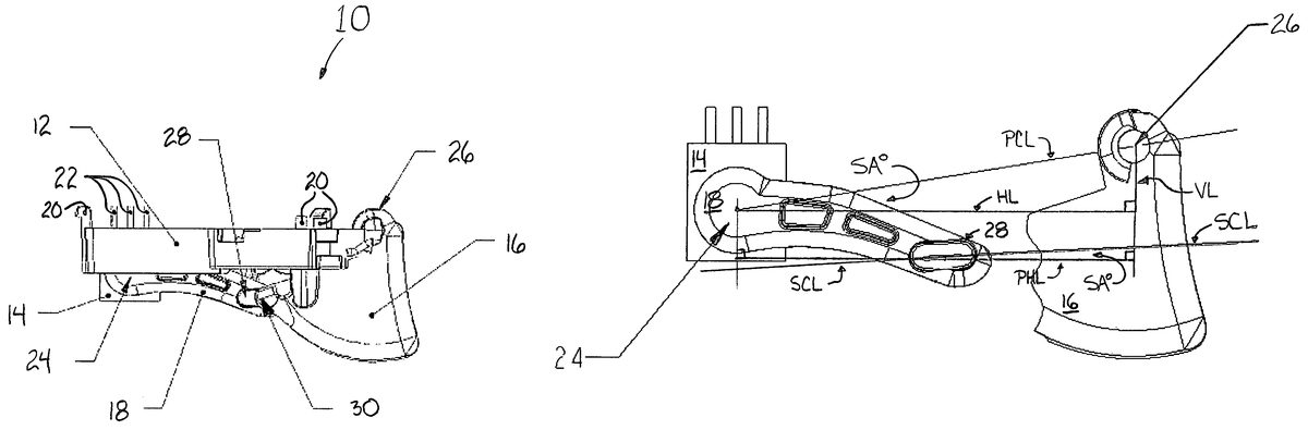
DETAILED DESCRIPTION OF ILLUSTRATIVE EMBODIMENTS Referring now to the drawings, wherein like numerals indicate like elements, there is shown inFIGS. 1-4a portion of a game controller10according to one embodiment of the invention. The game controller10includes a mount12, an analogue input device14, such as a potentiometer, and a user-activated control16, such as a trigger or lever, and a link mechanism18. The mount12attaches to a circuit board (not shown) using clips20. The analog input device14is fixed to the mount12and electrically communicates with the circuit board using connectivity pins22. The link mechanism18is fixed to a rotatable operational controller24of the analogue input device14. The rotatable operational controller24can be a stem or axle of a potentiometer14, and may be referred to herein as a potentiometer shaft or stem, or as a link mechanism pivot point24. The user-activated control16, or trigger, is rotatably connected to the mount12by a hinge-type configuration at a trigger pivot point26. A post30extends transversely from a plane of the trigger16and is contained within a slot28of the link mechanism18. The post30slidably translates within the slot28during activation of the trigger16. Accordingly, the post30may also be referred to as the link/trigger joint30. It is understood that other embodiments of the invention could include a slot28disposed within the trigger16, with a post30extending from the link mechanism18. InFIGS. 1-4, the trigger16is shown in a spring-biased, disengaged position (or initial position). The trigger16is user-activated by a clockwise rotation (clockwise in relation to the view shown inFIGS. 1-4) of the trigger16about the trigger pivot point26. The sliding translation of the post30within the slot28during clockwise rotation of the trigger16causes the link mechanism18to rotate counter-clockwise about the link mechanism pivot point24, consequently causing a counter-clockwise rotation of the potentiometer axle24. Ideally, an angle of movement of the trigger16about the trigger pivot point26is equal to the angle of movement of the potentiometer ...
DETAILED DESCRIPTION OF ILLUSTRATIVE EMBODIMENTS
Referring now to the drawings, wherein like numerals indicate like elements, there is shown inFIGS. 1-4a portion of a game controller10according to one embodiment of the invention. The game controller10includes a mount12, an analogue input device14, such as a potentiometer, and a user-activated control16, such as a trigger or lever, and a link mechanism18.
The mount12attaches to a circuit board (not shown) using clips20. The analog input device14is fixed to the mount12and electrically communicates with the circuit board using connectivity pins22. The link mechanism18is fixed to a rotatable operational controller24of the analogue input device14. The rotatable operational controller24can be a stem or axle of a potentiometer14, and may be referred to herein as a potentiometer shaft or stem, or as a link mechanism pivot point24. The user-activated control16, or trigger, is rotatably connected to the mount12by a hinge-type configuration at a trigger pivot point26.
A post30extends transversely from a plane of the trigger16and is contained within a slot28of the link mechanism18. The post30slidably translates within the slot28during activation of the trigger16. Accordingly, the post30may also be referred to as the link/trigger joint30. It is understood that other embodiments of the invention could include a slot28disposed within the trigger16, with a post30extending from the link mechanism18.
InFIGS. 1-4, the trigger16is shown in a spring-biased, disengaged position (or initial position). The trigger16is user-activated by a clockwise rotation (clockwise in relation to the view shown inFIGS. 1-4) of the trigger16about the trigger pivot point26. The sliding translation of the post30within the slot28during clockwise rotation of the trigger16causes the link mechanism18to rotate counter-clockwise about the link mechanism pivot point24, consequently causing a counter-clockwise rotation of the potentiometer axle24.
Ideally, an angle of movement of the trigger16about the trigger pivot point26is equal to the angle of movement of the potentiometer axle24. This ideal rotational linearity optimizes a relationship between user action and game response, and contributes to maximizing user satisfaction with the game. Characteristics of the link mechanism18, implemented through various embodiments of the present invention, provides linearity, or near linearity, between the rotation angle of the trigger16and the rotation angle of the potentiometer14.
Referring now toFIG. 3, a vertical offset VO and horizontal offset HO are shown between the trigger pivot point26and the link mechanism pivot point (or potentiometer axle)24. The offset dimensions are factors determinative of link mechanism24characteristics necessary to provide linearity between trigger rotation angle and potentiometer rotation angle.
FIG. 4illustrates a link distance LD and a trigger distance TD associated with the game controller10. The link distance LD is defined as a straight line distance between the link mechanism pivot point24and the post, or link/trigger joint30. The trigger distance TD is defined as a straight line distance between the link/trigger joint30and the trigger pivot point26. In one embodiment of the invention, the link distance LD is equal to the trigger distance TD. Where link distance LD equals trigger distance TD, linearity exists between the trigger rotation angle and the potentiometer rotation angle. Accordingly, in this embodiment, every 1° of trigger16movement results in 1° of potentiometer axle24rotation.
In order to provide a relationship between the trigger16and the link mechanism18so that the link distance LD equals the trigger distance TD, the link mechanism18can be curved over an entirety of, or over a portion of, its length. A curved link mechanism also provides that a length of the slot28need not be as long as that required with a straight link mechanism. Dimensions of the vertical offset VO and the horizontal offset HO, as selected by designers and/or dictated by physical constraints of the game controller10, determine the optimal curvature of the link mechanism18necessary to achieve linearity, or near linearity, and determine whether the link mechanism18should be curved over an entirety of, or over only a portion of, its length. However, it is understood that, although not illustrated in the various figures, link embodiments of the present invention could include straight link mechanisms18employing features of the invention detailed below.
FIG. 5illustrates another link mechanism18embodiment of the invention. InFIG. 5, only the link mechanism18is shown so that the entire slot28(without the post30slidably inserted therein) can be viewed. In this link mechanism18embodiment, the slot28is curved, following a radius of curvature over its entire length. In other embodiments, the slot28is curved over only a portion of its length, or the curvature is elliptical, or of any other shape, or the slot curvature possesses a combination of shapes over a portion of, or over an entirety of, its length. Curving the slot28provides an interaction between the trigger16and link mechanism18allowing a higher degree of linearity between trigger rotation angle and potentiometer rotation angle during game play. Curving the slot28, to provide a higher degree of linearity, is beneficial when physical constraints of the game controller preclude a design having link distance LD equaling trigger distance TD. An optimal radius of curvature would depend on link distance LD, trigger distance TD, vertical offset VO and horizontal offset HO. Further, the center of the radius of curvature could be located above or below the slot28. In theFIG. 5embodiment, the radius of curvature is 40 mm, and the center of the radius is above the slot28(as viewed inFIG. 5).
FIG. 6illustrates another link mechanism18embodiment of the invention, where the slot28is angled relative to horizontal; that is, an angle other than 0° exists between a longitudinal axis of the slot28, otherwise described as a line through center-points of ends of the slot28(shown as slot center line SCL), and any line parallel to (shown as parallel horizontal line PHL) a line intersecting the rotational pivot point24of the analogue input device14(shown as horizontal line HL) and forming a 90° angle with a line intersecting the rotational pivot point26of the user-activated control16(shown as vertical line VL).
Further, the line through slot end center-points (slot center line SCL) also does not intersect the link mechanism pivot point24. Angling the slot28as described also provides interaction between the trigger16and the link mechanism18facilitating a higher degree of linearity between trigger rotation angle and potentiometer rotation angle. A slot angle SA° optimizing linearity would again depend upon link distance LD, trigger distance TD, vertical offset VO and horizontal offset HO, as selected by designers and/or dictated by physical constraints of the game controller10. In various embodiments of the invention, the slot28could be angled above or below horizontal (i.e., parallel horizontal line PHL). In theFIG. 6embodiment, the slot is angled above horizontal, and the angle SA° of the slot28is 2.5°. Typical angles might range between 0.5° and 10°.
In a more specific embodiment of the invention shown inFIG. 6, the angle between the longitudinal axis of the slot28(slot center line SCL) and any line parallel to a line intersecting the rotational pivot point24of the analogue input device14and forming a 90° angle with a line intersecting the rotational pivot point26of the user-activated control16(again, shown as parallel horizontal line PHL) equals an angle between the line intersecting the rotational pivot point24of the analogue input device14and forming a 90° angle with a line intersecting the rotational pivot point of the user-activated control (horizontal line HL) and a line intersecting the rotational pivot point of the user-activated control and the rotational pivot point of the analogue input device (shown as pivot center line PCL). In this specific embodiment, the various locations identified as slot angle SA° include angle values.
Optimizing linearity between trigger rotation angle and potentiometer rotation angle might be found when the slot is angled and curved. In the specific link mechanism18embodiment shown inFIGS. 1-4, the slot28is both angled and curved, having a radius of curvature of 40 mm, with center located above the slot28, and having a slot angle of 2.5° above horizontal.
Where physical constraints of the game controller preclude link distance LD equaling trigger distance TD, the curved link mechanism18embodiments, curved slot28embodiments and/or angled slot28embodiments of the present invention provide a higher degree of linearity between user action and game response than a straight link mechanism having a straight and un-angled slot, as the following will illustrate.
FIG. 7illustrates a relationship between trigger rotation angle TA° and potentiometer rotation angle PA° when a straight link mechanism18is used, one having a straight, un-angled slot28, and one where a line through the slot end center-points (slot center line CL) intersects the link mechanism pivot point24. InFIG. 7, an initial position IP of the components, where the trigger16is spring-biased in a disengaged position, is shown in lighter print. As the trigger16is engaged and rotated clockwise about the trigger pivot point26, increments of trigger rotation angle TA° are recorded versus resulting potentiometer rotation angle PA°. The resulting potentiometer rotation angle PA° is caused by interaction between the trigger16and the link mechanism18; and more particularly by the slidable interaction of the post30within the slot28.
Table 1 charts the relationship of incremental trigger rotation angle TA° versus resulting potentiometer rotation angle PA° for the example shown inFIG. 7. In this straight link mechanism example, having a straight, un-angled slot, the initial link distance LD is 19.56 mm (i.e., link distance prior to trigger engagement and rotation), the horizontal offset HO is 38.30 mm, the vertical offset VO is 6.04 mm, and the link distance LD is not equal to the trigger distance TD. Table 1 shows that for every 0.5° increment of trigger rotation angle TA°, the resulting increment of potentiometer rotation angle PA° ranges between 0.33° and 0.51°.
Table 1 illustrates that the straight linkage configuration ofFIG. 7introduces an angular discrepancy error of +/−11.5% between trigger rotation angle TA° and potentiometer rotation angle PA°. Accordingly, the resulting relationship between user input (when a user depresses the trigger) and game response (angular movement of the potentiometer axle) is non-linear, as illustrated inFIG. 9. For instance, a 22° turn of the trigger produces a 19.4° turn of the potentiometer.
FIG. 8graphs the incremental potentiometer rotation angle PA°, for the straight link mechanism configuration ofFIG. 7, relative to each 0.5° incremental increase in trigger rotation angle TA°. Ideally, if linearity were to exist, the graph would be a straight, horizontal line at 0.50 on the y-axis.
FIG. 9graphs total potentiometer rotation angle PA°, for the straight link mechanism configuration ofFIG. 7, relative to total trigger rotation angle TA°. Ideally, if linearity were to exist, the graph would show a straight line, with a one to one relationship between x-axis and y-axis values.
FIG. 10illustrates a relationship between trigger rotation angle TA° and potentiometer rotation angle PA° using the link mechanism18embodiment of the present invention shown inFIGS. 1-4. TheFIG. 10embodiment has curvature over a portion of the length of the link mechanism18, and has a slot28that is both angled and curved. The radius of curvature of the slot28is 40 mm, with radius center located above the slot28. The slot28is also angled 2.5° above horizontal. Further, a line drawn through the slot end center-points (slot center line CL) of theFIG. 10embodiment does not intersect the link mechanism pivot point24. InFIG. 10, an initial position IP of the components, where the trigger16is spring-biased in a disengaged position, is shown in lighter print. As the trigger16is engaged and rotated clockwise about the trigger pivot point26, increments of trigger rotation angle TA° are recorded versus resulting potentiometer rotation angle PA°.
Table 2 charts the relationship of incremental trigger rotation angle TA° versus resulting potentiometer rotation angle PA° for the embodiment of the present invention shown inFIG. 10. For purposes of comparison, the values of link distance LD, trigger distance TD, horizontal offset HO and vertical offset VO, in this embodiment, are identical to those in the straight link mechanism example ofFIG. 7. That is, the link distance LD is 19.56 mm, the horizontal offset HO is 38.30 mm, and the vertical offset VO is 6.04 mm. As in the straight linkage example, the link distance LD is not equal to the trigger distance TD. Table 2 shows that for every 0.5° increment of trigger rotation angle TA°, the resulting increment of potentiometer rotation angle PA° ranges between 0.42° and 0.51°.
Table 2 illustrates that the curved link mechanism of the present invention, as shown inFIG. 10(and as shown inFIGS. 1-4) reduces the angular discrepancy error between trigger rotation angle TA° and potentiometer rotation angle PA° to +/−2.2%. The resulting relationship between user input (when a user depresses the trigger) and game response (angular movement of the potentiometer axle) involves and benefits from a higher degree of linearity than in the straight linkage example, as illustrated inFIG. 12. For example, with theFIG. 10embodiment of the present invention, a 22° turn of the trigger produces a 21.5° turn of the potentiometer axle, rather than a 19.4° turn of the potentiometer axle (as in the straight linkage example ofFIG. 7).
FIG. 11graphs the incremental potentiometer rotation angle PA°, for theFIG. 10embodiment of the present invention, relative to each 0.5° incremental increase in trigger rotation angle TA°. As shown inFIG. 11, the graph represents a much higher degree of linearity.
FIG. 12graphs total potentiometer rotation angle PA°, for theFIG. 10embodiment, relative to total trigger rotation angle TA°. Again, the graph illustrates a higher degree of linearity, with a much closer to one to one relationship existing between the x-axis and y-axis values.
These and other advantages of the present invention will be apparent to those skilled in the art from the foregoing specification. Accordingly, it will be recognized by those skilled in the art that changes or modifications may be made to the above-described embodiments without departing from the broad inventive concepts of the invention. For example, use of the link mechanism of the present invention is not limited to video game controllers, but rather the several embodiments of the invention could provide a higher degree of linearity of rotational movement between any two rotationally interacting mechanisms located a distance apart. It should therefore be understood that this invention is not limited to the particular embodiments described herein, but is intended to include all changes and modifications that are within the scope and spirit of the invention.
TABLE 1Trigger with straight linkageTriggerPotPotAngulardistancedistanceincrementsTriggerto triggerto triggerPotto initialShaftpivot - Xpivot - YPotAngular(deg)LengthdirectiondirectionAngularincrementsconstants0.519.5638.306.04incrementsto initialinitial value0000.50.330.3310.340.671.50.341.0120.351.372.50.361.7230.362.083.50.372.4540.372.834.50.383.2150.393.595.50.393.9860.404.386.50.404.7870.415.197.50.415.6180.426.038.50.426.4590.436.889.50.447.32100.447.7610.50.448.20110.458.6511.50.459.10120.469.5612.50.4610.03130.4710.4913.50.4710.96140.4711.4414.50.4811.92150.4812.4015.50.4912.89160.4913.3716.50.4913.86170.4914.3617.50.5014.86180.5015.3518.50.5015.86190.5016.3619.50.5016.86200.5117.3720.50.5117.87210.5118.3821.50.5118.89220.5119.4022.50.5119.91
TABLE 2Trigger with curved linkageTriggerPotPotAngulardistancedistanceincrementsTriggerto triggerto triggerPotto initialShaftpivot - Xpivot - YLinkagePotAngular(deg)LengthdirectiondirectionRadiusAngularincrementsconstants0.519.5638.306.0440.00incrementsto initialinitial value000.00.50.420.410.420.81.50.431.320.431.72.50.442.130.442.63.50.443.040.453.54.50.453.950.464.45.50.464.860.465.36.50.475.870.476.27.50.486.780.487.28.50.487.790.498.29.50.498.7100.499.110.50.509.6110.5010.111.50.5010.6120.5011.212.50.5111.7130.5112.213.50.5112.7140.5113.214.50.5113.7150.5214.215.50.5214.7160.5215.316.50.5215.8170.5216.317.50.5216.8180.5217.318.50.5217.8190.5218.419.50.5218.9200.5219.420.50.5219.9210.5220.421.50.5120.9220.5121.522.50.5122.0
Claims
- A game controller comprising: a mount member;a trigger member hingedly mounted to the mount member to enable rotation of the trigger member about a trigger pivot point in response to user manipulation of the trigger member;an analogue input device comprising a rotatable control member coupled to the mount member;and a link member, which is coupled to the trigger member and the rotatable control member and operatively mounted to pivot about a link pivot point in response to user manipulation of the trigger member, to translate a rotation of the trigger member about the trigger pivot point to a rotation of the rotatable control member, wherein: the link member is operatively coupled to the trigger member by a post member that slidably engages a slot to enable translation of the rotation of the trigger member about the trigger pivot point to the rotation of the rotatable control member;a longitudinal axis of the slot does not intersect the trigger pivot point or the link pivot point;and the rotatable control member of the analogue input device is an elongated rotatable shaft that is aligned with an axis of rotation of the link member which intersects the link pivot point.
- The game controller of claim 1 , wherein the slot is an element of the link member and the post is an element of the trigger member that extends from the trigger member.
- The game controller of claim 1 , wherein a length of the link member is curved over at least a portion thereof.
- The game controller of claim 1 , wherein the slot is curved to facilitate linearity or near linearity of the translation of the rotation of the trigger member and the rotation of the rotatable control member.
- The game controller of claim 4 , wherein a radius of the curved slot is centered above the link member and the slot is curved about the radius over an entirety of the slot.
- The game controller of claim 1 , wherein an angle other than 0° exists between a longitudinal axis of the slot and any line parallel to a line intersecting the link pivot point and forming a 90° angle with a line intersecting the trigger pivot point, whereby the angled slot facilitates linearity or near linearity of the translation of the rotation of the trigger member and rotation of the rotatable control member.
- The game controller of claim 6 , wherein the angle between the longitudinal axis of the slot and any line parallel to a line intersecting the link pivot point and forming a 90° angle with a line intersecting the trigger pivot point equals an angle between the line intersecting the link pivot point and forming a 90° angle with a line intersecting the trigger pivot point and a line intersecting the trigger pivot point and the link pivot point.
- The game controller of claim 7 , wherein the slot is additionally curved about a radius to further facilitate linearity or near linearity of the translation of the rotation of the trigger member and the rotation of the rotatable control member.
- The game controller of claim 1 , wherein a distance between the trigger pivot point and the post equals a distance between the post and the link pivot point.
- The game controller of claim 1 , wherein the trigger pivot point is vertically offset from the link pivot point.
- The game controller of claim 1 , wherein the post is vertically offset from each of the trigger pivot point and the link pivot point.
- A game controller comprising: a trigger member that can be pulled by a finger of a user, the trigger member being hingedly mounted on the controller to enable rotation of the trigger member about a trigger pivot point;an analogue input device;and a link mechanism, which is operatively mounted to rotate about a link pivot point in response to user manipulation of the trigger member, for communicating a rotational movement of the trigger member to operation of the analogue input device through a joint mechanism which comprises a post that slidably engages a curved slot slidably coupled to the link mechanism and trigger member, wherein: a longitudinal axis of the slot does not intersect the trigger pivot point or the link pivot point;and a rotatable control member of the analogue input device is an elongated rotatable shaft that is aligned with an axis of rotation of the link mechanism which intersects the link pivot point.
- The game controller of claim 12 , wherein a line defined by center-points of ends of the slot does not intersect the link pivot point or the trigger pivot point.
Disclaimer: Data collected from the USPTO and may be malformed, incomplete, and/or otherwise inaccurate.