U.S. Pat. No. 7,628,688
GAME APPARATUS, GAME CONTROL METHOD, RECORDING MEDIUM AND PROGRAM
AssigneeKonami Holding Corp.
Issue DateMarch 8, 2001
U.S. Patent No. 7,628,688: Game apparatus, game control method, recording medium and program
U.S. Patent No. 7,628,688: Game apparatus, game control method, recording medium and program
Issued December 8, 2009, to Konami Holding Corp.
Priority Date March 10, 2000

Summary:
Battling opponents is a quintessential part of gaming, and U.S. Patent No. 7,628,688 (the ‘688 Patent) helps these battles take place. The ‘688 patent describes an image generator used to display both a player and opponent in a state of combat, as well as showing the characters fighting in real time. The patent describes a detector that tracks the distance between a player and opponent. The game will switch normal gameplay and a combat mode based on the distance between players. For example, if a player or opponent enters a certain area (usually within a distance sufficiently close to the opponent), either the opponent or player satisfies a preset condition to initiate a battle. Once the conditions for ending the combat are met (i.e. the player wins or loses), the battle would end and switches back to normal gameplay. The patent describes that the game map has a number of geographic features that influence whether the elements are met for a battle to begin. For example, a character could hide behind a wall close to an opponent and avoid a battle which would otherwise take place. This helps to simulate sneaking around an enemy.
Abstract:
An image data generator of this game apparatus generates, in a combat state, combat image data to display player’s combat elements that executes a combat and opponent’s combat elements fighting with the player’s combat elements on the display unit in real time. This game comprises a distance detector that detects a distance between the player’s combat element and the opponent’s combat element at the time of changing a normal state to the combat state, and displays an initial image at the beginning of the combat state in accordance with the distance therebetween.
Illustrative Claim:
1. A game apparatus for executing a war simulation game, comprising: a first generator for generating image data to display a normal state image on a preset display, which includes a map, at least one player’s element, and at least one opponent’s element, both elements being positioned on the map; a first controller for activating the first generator when operation data indicating an operation by a game player is sent to the first controller and controlling the first generator to generate the image data for the normal state image according to the operation data; a second generator for generating image data to display a combat state image on the preset display, which represents that one of the at least one player’s element fights against one of the at least one opponent’s element; a second controller for activating the second generator when the operation data is sent to the second controller and controlling the second generator to generate the image data in real time in response to the operation data, wherein the real time generation of image data is free of a turn-based generation of image data; and a selector for receiving the operation data, determining whether or not the operation data satisfies a preset condition, and sending the operation data to either the first controller or the second controller in accordance with the determination wherein the map of the normal state image comprises a plurality of areas, and each of the both elements is positioned in one of the plurality of areas respectively, wherein the second controller determines, according to the operation data, whether or not an area in which the desired player’s element is positioned is adjacent to an area in which the desired opponent’s element is positioned, and controls the second generator so that the displayed combat state image represents the desired player’s element to fight the desired opponent’s element in short-range circumstance when the area in which the desired player’s element is positioned is adjacent to the area in which the desired opponent’s element is positioned, while the display combat state image represents the desired player’s element to fight the desired opponent’s element in long-range circumstance when the area in which the desired player’s element is positioned is not adjacent to the area in which the desired opponent’s element is positioned, wherein the map comprises a matrix form having a plurality of geographic features that exert an influence upon a result of combat between the at least one player’s element and the at least one opponent’s element, wherein the preset condition is whether the operation data includes an instruction that desired one of the at least one player’s element should fight against desired one of the at least one opponent’s element, wherein the selector sends the operation data to the second controller when the operation data satisfies the preset condition, and wherein the movements of the at least one player’s element and the at least one opponent’s element are influenced by the plurality of geographic features of the map.
Research By: Rachel Johns
Edited By: Andrew F. Thomas
Illustrative Figure
Abstract
An image data generator of this game apparatus generates, in a combat state, combat image data to display player's combat elements that executes a combat and opponent's combat elements fighting with the player's combat elements on the display unit in real time. This game comprises a distance detector that detects a distance between the player's combat element and the opponent's combat element at the time of changing a normal state to the combat state, and displays an initial image at the beginning of the combat state in accordance with the distance therebetween.
Description
DETAILED DESCRIPTION OF THE PREFERRED EMBODIMENT A preferred embodiment of the present invention will be specifically described with reference to the accompanying drawings. A game apparatus of the present invention will be first explained. The game apparatus of the present invention is implemented as a game apparatus having hardware configured as illustrated inFIG. 1. A game apparatus main body2has two buses of a main bus B1and a sub-bus B2as illustrated in the figure. These buses B1and B2are connected or disconnected to/from each other via a bus interface INT. A main CPU (Central Processing Unit)10, which is composed of a microprocessor, a first vector processing unit (VPU0, hereinafter referred to as “first VPU”)20, a main memory11having a RAM (Random Access Memory), a main DMAC (Direct Memory Access Controller)12, an MPEG (Moving Picture Experts Group) decoder (MDEC)13, a second vector processing unit (VPU1, hereinafter referred to as “second VPU”)12, and a GIF (Graphical Synthesizer-interface)30, which functions as an arbiter for the first and second VPUs20and21, are connected to the main bus B1. Moreover, a graphical synthesizer (hereinafter referred to as “GS”)31is connected thereto via the GIF30. A CRTC (CRT controller)33for generating a video output signal is connected to the GS31. Though the CRTC is connected to a predetermined display unit for displaying a game image, the illustration of this display unit is omitted. The main CPU10reads in an activation program from a ROM17on the sub-bus B2via the bus interface INT at a game apparatus start-up time, and executes the activation program to operate an operating system. The main CPU10also controls a media drive60to read out an application program and data from a media61to store them to the main memory11. Moreover, the main CPU10performs geometry processing with respect to various kinds of data read from the media61, for example, three-dimensional object data (coordinate ...
DETAILED DESCRIPTION OF THE PREFERRED EMBODIMENT
A preferred embodiment of the present invention will be specifically described with reference to the accompanying drawings.
A game apparatus of the present invention will be first explained. The game apparatus of the present invention is implemented as a game apparatus having hardware configured as illustrated inFIG. 1.
A game apparatus main body2has two buses of a main bus B1and a sub-bus B2as illustrated in the figure. These buses B1and B2are connected or disconnected to/from each other via a bus interface INT.
A main CPU (Central Processing Unit)10, which is composed of a microprocessor, a first vector processing unit (VPU0, hereinafter referred to as “first VPU”)20, a main memory11having a RAM (Random Access Memory), a main DMAC (Direct Memory Access Controller)12, an MPEG (Moving Picture Experts Group) decoder (MDEC)13, a second vector processing unit (VPU1, hereinafter referred to as “second VPU”)12, and a GIF (Graphical Synthesizer-interface)30, which functions as an arbiter for the first and second VPUs20and21, are connected to the main bus B1. Moreover, a graphical synthesizer (hereinafter referred to as “GS”)31is connected thereto via the GIF30. A CRTC (CRT controller)33for generating a video output signal is connected to the GS31.
Though the CRTC is connected to a predetermined display unit for displaying a game image, the illustration of this display unit is omitted.
The main CPU10reads in an activation program from a ROM17on the sub-bus B2via the bus interface INT at a game apparatus start-up time, and executes the activation program to operate an operating system. The main CPU10also controls a media drive60to read out an application program and data from a media61to store them to the main memory11. Moreover, the main CPU10performs geometry processing with respect to various kinds of data read from the media61, for example, three-dimensional object data (coordinate values of vertices (representative points) of polygons) composed of a plurality of basic graphics (polygons) in cooperation with the first VPU20.
Additionally, in the main CPU10, there is provided a high-speed memory, which is referred to as SPR (Scratch Pad RAM), for temporarily storing the result of processing in cooperation with the first VPU20.
The first VPU20has a plurality of operators to carry out an operation of a real number of floating-point arithmetic. The first VPU20performs floating-point arithmetic in parallel using these operators. Namely, the main CPU10and first VPU20perform arithmetic processing, which requires a precise operation on a polygon basis, among geometry processing. Then, they generate a display list having polygon definition information as its content such as a vertex coordinate sequence, shading mode information and so on obtained by this processing.
Polygon definition information is composed of drawing region setting information and polygon information. Drawing region setting information is made up of an offset coordinate at a frame buffer address of the drawing region and a coordinate of a drawing clipping region to cancel the drawing when a polygon coordinate is placed at the outside of the drawing region. Polygon information is composed of polygon attribute information and vertex information. Polygon attribute information is information for specifying a shading mode, an α blending mode, and a texture mapping mode. Vertex information includes a vertex drawing inner region coordinate, a vertex texture inner region coordinate and a vertex color, etc.
As is the case with the first VPU20, the second VPU21has a plurality of operators to carry out an operation of a real number of floating-point arithmetic. The second VPU21performs floating-point arithmetic in parallel using these operators. Then, the second VPU21generates a display list having an image generated by an operation of a control unit81and an operation of a matrix, e.g., relatively easy two-dimensional polygon definition information as its content, which can be generated by processing of, e.g., perspective conversion with respect to a simple-shaped object such as a building, a car, etc., a parallel light source calculation, generation of a two-dimensional curvature, and so on.
Though the first VPU20and second VPU21have the same configuration, they function as a geometry engine that starts arithmetic processing with a different content. Normally, processing (non-fixed geometry processing) for character movement, which needs a complicated behavior calculation, is assigned to the first VPU20. Then, processing (fixed geometry processing) for an object, which is simple but needs numerous polygons, for example, a background building and the like, is assigned to the second VPU21.
The first VPU20performs macro arithmetic processing to be synchronized with a video rate, and the second VPU21is designed to operate in synchronization with the GS31. For this purpose, the second VPU21is equipped with a direct path directly connecting to the GS31. Conversely, the first VPU20is closely connected to a microprocessor provided in the main CPU10to facilitate programming of complicated processing.
The first VPU20and second VPU21generate the display lists. The generated display lists are transferred to the GS31via the GIF30.
The GIF30performs arbitration to prevent occurrence of a collision at the time of transferring the display lists generated by the first VPU20and second VPU21to the GS31. In this embodiment, however, a function of checking these display lists in order of priority to transfer them to the GS31from the higher display list is added to the GIF30. Information indicating priority of the display lists is generally described in its tag region when the VPUs20and21generate display lists, but the GIF may determine the priority originally.
The GS31holds drawing contexts. The GS31reads the corresponding drawing context based on identification information of image contexts included in the display lists notified from the GIF30. Then, the GS31performs rendering processing by use of the read drawing context to draw a polygon in a frame memory32. The frame memory32can be used as a texture memory, so that a pixel image on the frame memory is also used as a texture to be adhered onto a polygon to be drawn.
Referring back toFIG. 1, the main DMAC12provides DMA transfer control to the respective circuits connected to the main bus B1, while provides DMA transfer control to the respective circuits connected to the sub-bus B2in accordance with the state of bus interface INT.
The MDEC13operates concurrently with the main CPU10, and decompresses data compressed in MPEG (Moving Picture Experts) or JPEG (Joint Photographic Experts Group).
A sub-CPU14comprising a microprocessor and so on, a sub-memory15having a RAM, a sub-DMAC16, a ROM17having a program such as an operating system and the like stored therein, a sound processing unit (SPU)40that reads sound data stored in a sound memory59to output as an audio output, a communication controller (ATM)50that performs data transmission/reception via a public switched telephone network, a media drive60for attaching a recording medium61such as a CD-ROM and DVD-ROM, and an input unit70are connected to the sub-bus B2. The input unit70includes a connection terminal71for connecting a control unit81, a connection terminal72for connecting a memory card MC, a video input circuit73for inputting image data from an external unit, and an audio input circuit for inputting sound data from an external unit.
The control unit81corresponds to inputting means of the present invention.
The sound processing unit40is connected to a speaker (not shown) of the present invention to output effective sounds.
The sub-CPU14performs various kinds of operations in accordance with a program stored in the ROM. The sub-DMAC16provides the DMA transfer control to the respective circuits connected to the sub-bus B2only when the main bas B1and sub-bus B2are separated from each other by the bus interface INT.
The game apparatus of this embodiment also performs characteristic geometry processing. As mentioned above, the concurrent operation of first VPU20and second VPU21makes it possible to perform geometry processing, which is adaptable to high-speed rendering processing. Hereinafter, as to whether the result of arithmetic processing obtained by the first VPU20is directly sent to the GIF30or serially sent thereto via the second VPU21, the selection is designed to be performed by software. The former mode is referred to as a parallel connection and the latter mode is referred to as a serial connection. In either case, the output of second VPU21has a path directly connected to the GIF30(GS31) and performs a coordinate conversion in synchronization with timing of rendering processing of the GS31. As a result, the standby state of GS31is not maintained more than necessary.
In the above-arranged game apparatus, when the recording medium61of the present invention having, for example, a CD-ROM is attached to the disk drive41and power is turned on or reset processing is performed, the main CPU10executes OS recorded in the ROM17. When OS is executed, the main CPU10initializes the entirety of the apparatus to confirm the operation and the like and controls the disk controller40to execute a game program recorded in a CD-ROM44after reading it to the main memory13. The execution of this game program allows the main CPU10to form the function block shown inFIG. 2and to implement the game apparatus2of the present invention.
As illustrated inFIG. 2, the game apparatus of this embodiment comprises an instruction information analyzer110, a game controller120, and an image data generator130.
The instruction information analyzer110is connected to the control unit81, and determines the operation content inputted from the control unit81by the game player. The operation content analyzed by the instruction information analyzer110is sent to the game controller120to be reflected in control of executing the game.
The game controller120integrally controls the entirety of game to be executed by the present invention, and corresponds to control means of the present invention.
In addition, the game executed by the game apparatus of the present invention is a war simulation game. The war simulation game to be executed by this game apparatus can be described as follows:
A map image of a map, which is divided into rectangular small regions formed in a matrix, is displayed on the display unit and combat elements, which fight with each other, are displayed on some small regions so that the combat is deployed as moving the combat elements appropriately in accordance with instructions from the game player. This war simulation game is executed by alternately repeating a normal state and a combat state wherein the normal state indicates that movement of the combat elements is performed and the combat state indicates that the combat elements fight with each other in the normal state.
The game controller120comprises a selector121, a normal state controller122, and a combat state controller123as shown inFIG. 3.
The selector121selects the normal state or combat state in accordance with the operation content inputted by the game player via the control unit81. Then the selector121sends data outputted from the instruction information analyzer110to the normal state controller122or the combat state controller123according to the selection.
The normal state controller122performs control in the normal state. The combat state controller123performs control in the combat state. Data of each of the normal state controller122and the combat state controller123is sent to an image data generator130to be described later to be reflected in generation of an image to be displayed on the display unit.
The combat state controller123comprises a distance detector123A, which corresponds to distance detecting means of the present invention. The distance detector123A is capable of receiving data from the selector121. At the time of receiving the data, the distance detector123A detects a distance between the player's combat element to execute the combat according to the player's operation content inputted by the game player among the player's combat elements and the opponent's combat element fighting with the player's combat element, whereby generating distance data of the corresponding distance. The generated distance data is sent to the image generator130.
The image data generator130generates image data to display a desired image on the display unit. The display unit displays an image based on this image data. This image data generator130corresponds to image data generating means of the present invention.
The image data generator130comprises a normal state image determining unit131, a combat state image determining unit132, and a data generator133as shown inFIG. 4. The normal state image determining unit131determines an image to be displayed on the display unit in the normal state. The combat state image determining unit132determines an image to be displayed on the display unit in the combat state. The data generator133generates final image data based on data, which is indicative of the image to be displayed on the display unit and which is sent from either the normal state image determining section131or the combat state image determining section132.
The normal state image determining section131includes a map data generator131A, a cursor data generator131B, a specified position determining unit131C and a 3D map data recorder131D.
The 3D map data recorder131D records 3D map data.
This 3D map data is data of a map, which includes three-dimensional information and which is used to generate map data about a display map to be display on the display unit in the normal state. The 3D map data is designed to generate such a display map that is divided into small square regions formed in a matrix though data is not limited to this.
The map data generating section131A generates map data about a two-dimensional display map to be displayed on the display unit based on 3D map data read from the 3D map data recording section131D. The map data is sent to the data generator133.
The map data generator131also generates combat element data for displaying the player's combat element and the opponent's combat element on the display wherein the player's combat element moves based on the operation content inputted by the gamer player via the control unit81and the opponent's combat element moves automatically upon receipt of control of predetermined data. It is noted that the opponent's combat element may execute movement and combat automatically under control of the game controller120or based on the operation content inputted by the other player.
The combat element described herein indicates one that is movable on the 3D map and fights with an enemy combat element. For example, the combat element is expressed as a tank, a flat land, a foot soldier, etc., depending on the kinds of war simulation games.
The cursor data generator131B displays a two-dimensional cursor at a predetermined position on the screen based on the operation content inputted by the player via the control unit81. The cursor data generator131B generates cursor data for displaying the cursor on the screen. The data is sent to the data generator133.
The specified position determining unit131C determines a position on the 3D map specified by the cursor. Position data about the position specified by the cursor is sent to the data generator133.
The combat state image determining unit132determines an image to be displayed on the display in the combat state. Specifically, the combat state image determining unit132determines what image should be displayed on the display based on data generated by the combat state controller123.
Actions of the game apparatus of this embodiment will be next explained in connection with one embodiment of the specified position determining method according to the present invention. This game apparatus executes the specified position determining method of the present invention with a flow shown byFIG. 5.
Power source is turned on or reset processing is performed, and the game player inputs the operation content of the game start via the control unit81, whereby the game apparatus starts a war simulation game (S201).
When the game is started, the normal state is initiated (S202), so that the screen page of the normal state is displayed on the display unit. Namely, the selector121selects the normal state in an initial state.
On the screen page of the normal state, the display map, which expresses the 3D map two-dimensionally, the player's combat elements, the opponent's combat elements, and the cursor are displayed. An example of the image displayed on the display unit at this time is illustrated inFIG. 6.
The display map, combat elements, and cursor are displayed as follows:
Specifically, the map data generator131A reads 3D data map including three-dimensional data including three-dimensional data from the 3D map data recorder131D, and converts it to map data about two-dimensional display map, whereby generating the display map.
A display map M is as shown inFIG. 6. Namely, the display map M is divided into square small regions M1, M1, . . . in a matrix form. In this example, different geographical features such as a flat ground, a river, a mountainous district, and the like are given to the respective small regions M1, M1, . . . These features exert an influence upon the result of combat at each of the small regions M1, M1, . . . That is, the combat elements S1, S1, . . . have intrinsic properties, respectively, and advantageous small regions M1, M1, . . . and disadvantageous regions M1, M1, . . . are predetermined. The game player works out a strategy of movement of each of player's combat elements S1, S1, . . . with consideration given to such geographical features.
These combat elements S1, S1, . . . are designed to move in accordance with data generated by the instruction information analyzer110based on the operation content inputted by the player via the control unit81. The map data generator131A generates combat element data for displaying the respective combat elements S1, S1, . . . on the display unit based on data generated by the instruction information analyzer110under the normal state controller122.
It is noted that the respective combat elements S1, S1, . . . are designed to move in the unit of small regions M1, M1, . . . as a minimum unit. The opponent's combat elements M1, M1. . . move in the unit of small regions M1, M1. . . under the normal state controller122, and the player's combat elements are designed to move to the small regions M1, M1, . . . , which the player has specified with the cursor C.
The cursor C is displayed based on cursor data generated by the cursor data generator131B. The cursor data originally has only two-dimensional information and is expressed two-dimensionally.
The cursor data is generated by the cursor data generator131B based on the operation content inputted by the game player via the control unit81. In accordance with the instructions of movement in upper and lower and right and left directions inputted by the game player using the controller, the cursor C is controlled to be moved to the corresponding direction. Data necessary for this control is inputted to the cursor data generator131B via the control unit81, the instruction information analyzer110, and the normal state controller122.
Axes in the upper and lower and right and left directions where the cursor C moves are directions indicated by XC and XY in the figure, and they deviate from axes XM and YM in the upper and lower and right and left directions about the display map M. Namely, the moving direction of the cursor C is controlled regardless of the axes XM and YM in the upper and lower and right and left directions on the display map M.
In the normal state, it is also determined as to which position on the 3D map the cursor C specifies. Namely, when the game player moves the player's combat elements S1, S1, . . . , small regions M1, M1, . . . , must be specified by the cursor C. Accordingly, the specified position determining unit13IC determines the position on the 3D map, which the cursor C specifies, by the way set forth below.
The specified position determining unit131C determines not only the position on the 3D map specified by the cursor C but also which small region M1the cursor C specifies.
This determination is performed by the method as shown inFIG. 7. It is noted thatFIG. 7schematically and conceptually shows this determination method.
According to this method, an image G, which is displayed on the display unit, and a predetermined viewpoint E, which is placed in front of the image G are imaginarily formed. Next, a rectangular 3D map3DM with its four corners is imaginarily formed on straight lines passing through four corners of the image G. It is assumed that the 3D map3DM is placed to be parallel with the image G at a backward position seeing from the viewpoint E of the image G. This 3D map corresponds to the display map displayed on the display unit. At this time, the specified position determining unit131C uses, for example, 3D map data obtained from the 3D map recorder131D via the map data generator131A in order to form the 3D map 3D imaginarily.
Then, in this state, a straight line passing through the viewpoint E and a predetermined position of the cursor C (e.g., top portion of the cursor C indicated by an arrow shape) is imaginarily formed. Next, it is detected at which position on 3D map3DM the straight line intersects. After that, it is also detected in which small region M1a point of intersection exists. This detects with which small region M1the cursor C has a point of intersection.
Then, by fixing that the cursor C specifies the small region M1where the point of intersection exists, it is determined which small region M1the cursor C specifies.
In this embodiment, data of which small region M1the cursor C specifies is sent to the map data generator131A. As a result, the map data generator131A uses the above data in generating combat element data after deciding destinations of combat elements S1, S1.
The above data can be used as follows though this is not always needed.
Specifically, the above data can be used to generate image data for displaying a small region S1specified by the cursor C at the current point on the display unit as distinguished from other small regions S1, S1, . . . This can be attained by, for example, making a difference in color between the small region S1and other regions S1, S1. . . or adding some pattern to the small region S1though the illustration is omitted. Data generated in this case is capable of displaying such a color and a pattern.
The image displayed on the display unit in the normal state is displayed based on image data generated when the data generator133combines map data, combat element data and cursor data generated as mentioned above.
In the normal state, a determination whether or not a predetermined condition about the start of combat is satisfied is performed (S203). For example, this condition is satisfied when the game player inputs the operation content, which corresponds to the instructions in which the predetermined player's combat elements S1, S1are fought with the opponent's combat elements S1, S1, via the control unit81or when the normal state controller122supports the start of combat in accordance with the predetermined condition. The determination whether or not this condition is satisfied is performed by, for example, the selector121.
When this condition is satisfied (S203: YES), the selector121sends data which is outputted from the instruction information analyzer110, to the combat state controller121. The combat state controller121receives it and starts to control the combat state, so that the combat state is started (S204). When the condition is not satisfied (S203: NO), the normal state is continued.
When the combat state is started, an image, which shows a situation in which the player's combat element S1and the opponent's combat element S2are fighting with each other, is displayed on the display unit in real time.
This image is displayed on the display unit in accordance with image data, which the data generator133has generated based on data determined by the combat state image determining unit132under control of the combat state controller123. This image shows that the player's combat element executes an action in real time in accordance with the operation content inputted by the game player. Accordingly, the data generator133generates combat image data to display the player's combat element S1, which executes a combat in accordance with the operation content inputted by the game player among the player's combat elements S1, S1, and the opponent's combat element S1fighting with the player's combat element S1in real time. In other words, the player's combat element S1is displayed on the screen in real time in accordance with the operation content inputted by the game player. For example, the image as a moving image using a polygon is displayed on the display unit. One example of the image displayed on the display unit in the combat state is illustrated inFIG. 8.
At the combat state starting time, the following processing is carried out, whereby determining an initial screen page at the beginning of the combat state.
First, when the condition for starting the combat state is met, the aforementioned combat data is inputted to the combat state controller123. This data is also sent to the distance detector123A provided in the combat state controller123.
Upon receipt of this data, the distance detector123A detects a distance between the player's combat element S1, which executes the combat, and the opponent's combat element S1so as to generate distance data of the distance. This distance denotes, for example, a distance between both combat elements S1on the 3D map3DM.
Distance data may be one that is proportional to the distance between both combat elements S1. In this example, however, to simplify the explanation, two kinds of different distance data are generated depending on whether both combat elements S1, which are to fight with each other, are placed at the small regions M1adjacent to each other via the side or at a different position. Namely, the distance detector123A generates distance data indicating that both combat elements S1are placed in a close distance range in the former case and in a long distance range in the latter case.
This can be explained with reference toFIG. 9. In this example, it is assumed that the opponent's combat element S1is placed at the small region M1as illustrated in the figure. Distance data indicating that both are in the close distance range is generated only when the player's combat elements are placed at four small regions shown by diagonal lines. When the player's combat elements are placed at the other regions, distance data indicating that both are in the long distance range is generated.
Then, this data is sent to the combat state image determining unit132provided in the image data generator130. The combat state image determining unit132generates image data about the initial image displayed on the display unit in accordance with the distance data at the beginning of the change to the combat state. In this embodiment, when the combat state image determining unit132receives distance data indicating that both combat elements S1are placed in the close distance range, the combat state image determining unit132is configured to generate initial image data for displaying the initial image indicating that both combat elements are in the close distance range as compared with the case in which it receives data indicating that both combat elements are in the long distance range.
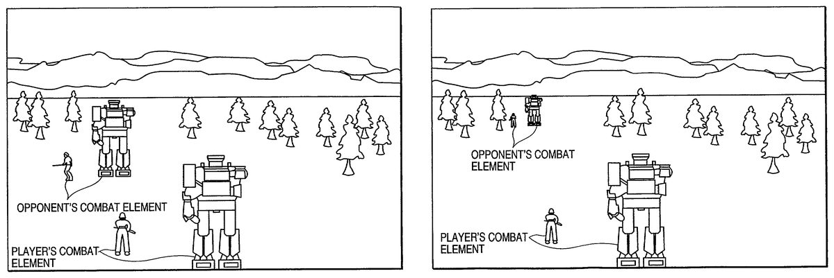
More specifically, this is illustrated as inFIGS. 10A and 10B.FIG. 10Ashows an example of the initial image in a case in which the combat state image determining unit132receives distance data indicating that both combat elements S1are placed in the close distance range.FIG. 10Bshows an example of the initial image in a case the combat state image determining unit132receives data indicating that both combat elements are in the long distance range. In either example, the soldier displayed at the front indicates the player's combat element S1and the solider displayed at the backward is the opponent's combat element S1.
According to these examples, in the case shown inFIG. 10Ain which distance data indicates that both combat elements S1are placed in the close distance range, the opponent's combat element S1is displayed largely as compared with the case inFIG. 10Bin which distance data indicates that both combat elements S1are placed in the long distance range.
In a case where distance data is data that shows numerous levels (or non-level), which are proportional to the distance, the distance between the player's combat element S1and the opponent's combat element S1can be variously expressed.
In the combat state, it is judged whether or not a fixed condition about the end of combat is met (S205). For example, when either of the player's combat element S1and the opponent's combat element S1, which are fighting with each other, is completely destroyed or annihilated, this condition can be met. The judgment whether this condition is met or not is performed by, for example, the selector121.
When this condition is met (S205: YES), the combat state is ended. When the combat state is ended, the selector121performs switching from the combat state to the normal state so as to start the normal state (S206). When this condition is not met (S205: NO), the combat state is continued.
In the normal state, it is judged whether or not a fixed condition about the end of the game is met (S207). For example, when all player's combat elements S1or opponent's combat elements S1are completely destroyed or either the player or the computer acknowledge one's defeat, this condition can be met.
When this condition is met (S207: YES), the war simulation game is ended (S208). When the combat state is ended, an image indicating whether the player is a victor or a loser or an end roll is displayed on the display unit.
When this condition is not met (S207: NO), the war simulation game is continued.
As explained above, the present invention can add new interest, which results from an immediate judgment and a quick operation of input means, to the war simulation game whose enjoyment lies in mainly working on a strategy as thinking it over for a long time.
Moreover, the distance between the player's combat element and the opponent combat element at the time of changing the normal state to the combat state is reflected in the image on the initial screen page at the beginning of the combat state, making it possible to provide the game player a new element to be considered. This further increases enjoyment in the war simulation game.
Various embodiments and changes may be made thereunto without departing from the broad spirit and scope of the invention. The above-described embodiment intended to illustrate the present invention, not to limit the scope of the present invention. The scope of the present invention is shown by the attached claims rather than the embodiment. Various modifications made within the meaning of an equivalent of the claims of the invention and within the claims are to be regarded to be in the scope of the present invention.
Claims
- A game apparatus for executing a war simulation game, comprising: a first generator for generating image data to display a normal state image on a preset display, which includes a map, at least one player's element, and at least one opponent's element, both elements being positioned on the map;a first controller for activating the first generator when operation data indicating an operation by a game player is sent to the first controller and controlling the first generator to generate the image data for the normal state image according to the operation data;a second generator for generating image data to display a combat state image on the preset display, which represents that one of the at least one player's element fights against one of the at least one opponent's element;a second controller for activating the second generator when the operation data is sent to the second controller and controlling the second generator to generate the image data in real time in response to the operation data, wherein the real time generation of image data is free of a turn-based generation of image data;and a selector for receiving the operation data, determining whether or not the operation data satisfies a preset condition, and sending the operation data to either the first controller or the second controller in accordance with the determination wherein the map of the normal state image comprises a plurality of areas, and each of the both elements is positioned in one of the plurality of areas respectively, wherein the second controller determines, according to the operation data, whether or not an area in which the desired player's element is positioned is adjacent to an area in which the desired opponent's element is positioned, and controls the second generator so that the displayed combat state image represents the desired player's element to fight the desired opponent's element in short-range circumstance when the area in which the desired player's element is positioned is adjacent to the area in which the desired opponent's element is positioned, while the display combat state image represents the desired player's element to fight the desired opponent's element in long-range circumstance when the area in which the desired player's element is positioned is not adjacent to the area in which the desired opponent's element is positioned, wherein the map comprises a matrix form having a plurality of geographic features that exert an influence upon a result of combat between the at least one player's element and the at least one opponent's element, wherein the preset condition is whether the operation data includes an instruction that desired one of the at least one player's element should fight against desired one of the at least one opponent's element, wherein the selector sends the operation data to the second controller when the operation data satisfies the preset condition, and wherein the movements of the at least one player's element and the at least one opponent's element are influenced by the plurality of geographic features of the map.
- The game apparatus according to claim 1 , wherein the second controller detects a distance between the desired player's element and the desired opponent's element according to the operation data, and controls the second generator so that the displayed combat state image reflects the detected distance.
- A method of executing a war simulation game on a game apparatus, comprising: a first generating step of generating image data to display a normal state image on a preset display of the game apparatus, which includes a map, at least one player's element and at least one opponent's element, both elements being positioned on the map;a first controlling step of activating the first generating step in response to reception operation data indicating an operation by a game player and controlling the first generating step to generate the image data for the normal state image according to the operation data;a second generating step of generating image data to display a combat state image on the preset display, which represents that one of the at least one player's element fights against one of the at least one opponent's element;a second controlling step of activating the second generating step in response to reception of the operation data and controlling the second generating step to generate the image data in real time in response to the operation data, wherein the real time generation of image data is free of a turn-based generation of image data;and a selecting step of receiving the operation data, determining whether or not the operation data satisfies a preset condition, and sending the operation data to either the first controlling step or the second controlling step in accordance with the determination, wherein the map of the normal state image comprises a plurality of areas having a plurality of geographic features, and each of the both elements is positioned in one of the plurality of areas respectively, and further comprising: step of determining, according to the operation data, whether or not an area in which the desired player's element is positioned is adjacent to an area in which the desired opponent's element is positioned, and controlling the second generator so that the displayed combat state image represents the desired player's element to fight the desired opponent's element in short-range circumstance when the area in which the desired player's element is positioned is adjacent to the area in which the desired opponent's element is positioned, while the display combat state image represents the desired player's element to fight the desired opponent's element in long-range circumstance when the area in which the desired player's element is positioned is not adjacent to the area in which the desired opponent's element is positioned, wherein the plurality of geographic features exert an influence upon a result of combat between the at least one player's element and the at least one opponent's element, wherein the preset condition is whether the operation data includes an instruction that desired one of the at least one player's element should fight against desired one of the at least one opponent's element, wherein the selector sends the operation data to the second controller when the operation data satisfies the preset condition, and wherein the movements of the at least one player's element and the at least one opponent's element are influenced by the plurality of geographic features of the map.
- A storage medium having computer readable program code means embodied in the medium, the computer readable program code means comprising: first computer readable program code means for generating image data to display a normal state image on a preset display, which includes a map, at least one player's element, and at least one opponent's element, both elements being positioned on the map, wherein the map of the normal state image comprises a plurality of areas having a plurality of geographic features, and each of the both elements is positioned in one of the plurality of areas respectively;second computer readable program code means for activating the first computer readable program code means in response to reception operation data indicating an operation by a game player and controlling the first computer readable program code means to generate the image data for the normal state image according to the operation data;third computer readable program code means for generating image data to display a combat state image on the preset display, which represents that one of the at least one player's element fights against one of the at least one opponent's element;fourth computer readable program code means for activating the third computer readable program code means in response to reception of the operation data and controlling the third computer readable program code means to generate the image data in real time in response to the operation data, wherein the real time generation of image data is free of a turn-based generation of image data;and fifth computer readable program code means for receiving the operation data, determining whether or not the operation data satisfies a preset condition, and sending the operation data to either the second computer readable program code means or the fourth computer readable program code means in accordance with the determination, and the computer readable program code means further comprising: computer readable program code means for determining, according to the operation data, whether or not an area in which the desired player's element is positioned is adjacent to an area in which the desired opponent's element is positioned, and computer readable program code means for controlling the second generator so that the displayed combat state image represents the desired player's element to fight the desired opponent's element in short-range circumstance when the area in which the desired player's element is positioned is adjacent to the area in which the desired opponent's element is positioned, while the display combat state image represents the desired player's element to fight the desired opponent's element in long-range circumstance when the area in which the desired player's element is positioned is not adjacent to the area in which the desired opponent's element is positioned, and the plurality of geographic features exert an influence upon a result of combat between the at least one player's element the at least one opponent's element;and wherein the preset condition is whether the operation data includes an instruction that desired one of the at least one player's element should fight against desired one of the at least one opponent's element, wherein the fifth computer readable program code means sends the operation data to the fourth computer readable program code means when the operation data satisfies the preset condition, and wherein the movements of the at least one player's element and the at least one opponent's element are influenced by the plurality of geographic features of the map.
Disclaimer: Data collected from the USPTO and may be malformed, incomplete, and/or otherwise inaccurate.