U.S. Pat. No. 7,625,286
ELECTRONIC DEVICE AND A GAME CONTROLLER
AssigneeSony Computer Entertainment Inc.
Issue DateMay 4, 2005
Illustrative Figure
Abstract
A portable electronic device includes a casing provided with a display on its front face and having ends gripped by both hands of a user, and at least one LR-button provided on a side face of the casing. The LR-button includes: an elongated button body having seizing members on both ends, the seizing members contacting against an inner side of the casing to prevent the button body from being detached from the casing; a deformation member pressed by a back of the button body when the button body is pressed; and switch contacts electrically conducted due to the deformation of the deformation member. When one end of the button body is pressed, the button body pivots about a contact point where said seizing means provided on the other end of the button body comes into contact with the casing.
Description
DETAILED DESCRIPTION OF THE PREFERRED EMBODIMENTS FIGS. 1 through 6are views showing the appearance of a portable electronic device100according to one embodiment of the present invention.FIG. 1is a front view of the portable electronic device100. A casing10has a horizontally long oval shape as a whole. Each end of the casing10is formed in a circular curve shape with its center decentered from a center line14by a certain distance. As shown inFIGS. 2 and 4, the casing10is composed of an upper part10a, an intermediate part10b, and a lower part10c. The casing10has a hollow body. Inside the casing10, a circuit board (not shown) is provided. The circuit board includes: switch contacts for generating a signal by the operation of various corresponding buttons; a CPU which processes the signals so as to execute various computations; a sound processor for outputting a sound; and an image processor for outputting an image. The intermediate part10bhas a higher rigidity than those of the upper part10aand the lower part10cto ensure the rigidity of the entire casing10. Returning toFIG. 1, a liquid crystal display12(hereinafter, abbreviated as an “LCD12”) serving as a display device is fit into the center of the upper part10aof the casing10. The LCD12displays, for example, a game screen when the portable electronic device100functions as a game machine or displays a schedule or an address list when the portable electronic device100functions as a personal digital assistant (PDA). The LCD12is fit into the upper part10aof the casing10through a frame96. The surface of the casing10, that is, the front face being opposite to the user is mainly composed of: a left-hand area48L gripped by the left hand of the user; a right-hand area48R gripped by the right hand of the user; the LCD12; a horizontally long button area50positioned below the LCD12, where various buttons are provided; and a decorative ...
DETAILED DESCRIPTION OF THE PREFERRED EMBODIMENTS
FIGS. 1 through 6are views showing the appearance of a portable electronic device100according to one embodiment of the present invention.FIG. 1is a front view of the portable electronic device100. A casing10has a horizontally long oval shape as a whole. Each end of the casing10is formed in a circular curve shape with its center decentered from a center line14by a certain distance.
As shown inFIGS. 2 and 4, the casing10is composed of an upper part10a, an intermediate part10b, and a lower part10c. The casing10has a hollow body. Inside the casing10, a circuit board (not shown) is provided. The circuit board includes: switch contacts for generating a signal by the operation of various corresponding buttons; a CPU which processes the signals so as to execute various computations; a sound processor for outputting a sound; and an image processor for outputting an image. The intermediate part10bhas a higher rigidity than those of the upper part10aand the lower part10cto ensure the rigidity of the entire casing10.
Returning toFIG. 1, a liquid crystal display12(hereinafter, abbreviated as an “LCD12”) serving as a display device is fit into the center of the upper part10aof the casing10. The LCD12displays, for example, a game screen when the portable electronic device100functions as a game machine or displays a schedule or an address list when the portable electronic device100functions as a personal digital assistant (PDA). The LCD12is fit into the upper part10aof the casing10through a frame96.
The surface of the casing10, that is, the front face being opposite to the user is mainly composed of: a left-hand area48L gripped by the left hand of the user; a right-hand area48R gripped by the right hand of the user; the LCD12; a horizontally long button area50positioned below the LCD12, where various buttons are provided; and a decorative area16positioned above the LCD12. Notches84L and84R are formed on an upper left corner and an upper right corner of the upper part10aof the casing10, respectively.
In the left-hand area48L, an arrow key20mainly for inputting a direction indication and an analog device22mainly for analog input of the direction indication are provided. The detailed structures and functions thereof will be described below. Indicators32and34are also provided in the left-hand area48L. The indicator32lights up during access to a removable recording medium, and the indicator34lights up during WLAN communication.
The horizontal center of the analog device22is located closer toward the center line14of the casing10than the horizontal center of the arrow key20. The analog device22is located closer to the lower left corner of the device than the arrow key20. The reason for this arrangement is as follows. When the left thumb of the user moves between the arrow key20and the analog device22at the time that both sides of the device are held by the user's hands, the user pivotally moves his thumb with his palm on the lower left corner of the casing10as a supporting point. And the user tilts the center of the analog device22for operation. Therefore, the operation is facilitated when the analog device22is positioned closer to the center of the casing10.
In the right-hand area48R, buttons30a,30b,30cand30d(hereinafter, also collectively referred to as “button keys30”) are provided mainly for inputting a unique instruction. A structure and functions of the button keys30will be described below. Additionally, indicators36,38and40are provided in the right-hand area48R. The indicator36lights up when the portable electronic device100is ON. The indicator38lights up while the portable electronic device100is being charged. The indicator40lights when the portable electronic device100is in a hold status where every key of the portable electronic device100is invalid.
As shown inFIG. 1, the center of the arrow key20and the center of the button keys30are preferably shifted upward from the horizontal center line of the casing10in the vertical direction.
The center of the arrow key20and the center of the button keys30are preferably located at the same distance from the center line14of the casing10in the horizontal direction. Each distance between pressed faces20a,20b,20cand20don a disc-like key top of the arrow key20is preferably set smaller than that between the buttons30a,30b,30cand30d. The reason for this arrangement is as follows. Since the arrow key20is mainly used to direct the vertical and horizontal movements, the user often keeps operating the arrow key20. Therefore, it is preferable that the user can operate the arrow key20without taking his thumb off the pressed faces of the arrow key20. In this regard, it is easier for the user to operate the arrow key20if the pressed faces20a,20b,20cand20dare not quite distant from each other. On the other hand, the button keys30are often used to give different instructions by respective buttons30a,30b,30cand30d. Therefore, since it is easier for the user to operate taking his thumb off the button keys30, it is preferable that the buttons30a,30b,30cand30dare located with a certain distance.
Below both ends of the LCD12, a speaker hole28L is provided in the left-hand area48L, and a speaker hole28R is provided in the right-hand area48R to provide a sound for the user.
The button area50is located in the vicinity of an outer edge of the upper part10aof the casing10on the side closer to the user holding the portable electronic device100. In the button area50, buttons52to64are located. Preferably, the button area50is constituted so as to be visually distinct from the left-hand area48L and the right-hand area48R. In this embodiment, the button area50is formed in a horizontally extending elongated hill-like shape. The button area50is elevated above the level of the plane formed by the left-hand area48L, the right-hand area48R and the LCD12. In the vicinity of the top of the hill, various buttons52to64are provided. With this arrangement, the user can visually distinguish the buttons to be operated during gameplay or an application operation from the other buttons. Furthermore, since the button area50is elevated, the user can be tactilely aware of the arrangement of these buttons52to64. The elevated shape of the button area50also serves to protect the LCD12.
The structure of the button area50is not limited to the above-described structure. Any structure may be employed as long as the height of the button area50differs from the height of the left-hand area48L and the right-hand area48R. Herein, the “height” means a height based on a horizontal plane, on which the casing10is placed so that its front face carrying the LCD12is oriented upward. For example, an elongated step having a trapezoidal or rectangular cross section may be provided to arrange the buttons52to64thereon. Alternatively, walls having the greater height than that of the buttons52to64may be provided above and below the buttons52to64arranged on the same plane with the left-hand area48L, the right-hand area48R and the LCD12. With these walls, the buttons52to64are not easily pressed down by the user's hands operating the arrow key20or the button keys30.
The buttons52to64arranged in the button area50are not frequently used for gameplay or a main operation of the other applications, and therefore the buttons52to64are not required to be frequently pressed. A home button52is used to turn the LCD12back to a main screen. A volume buttons54,56serve to decrease/increase the volume of a sound reproduced through a speaker or a headphone, respectively. A display button58turns ON/OFF a backlight of the LCD12. A sound button60turns ON/OFF a sound output. A select button62serves for selecting one item from items displayed on the LCD12. A start button64mainly serves to start a game when a game program is being executed.
In a conventional portable electronic device or game controller, such buttons52to64are provided, for example, below the arrow key or the button keys, not at a part distant from the part where the arrow key or the button keys are formed as described above. With such conventional arrangement, when the user operates the arrow key or the button keys, the finger of the user carelessly touches such buttons, sometimes leading to an erroneous operation. On the other hand, according to this embodiment, since the buttons52to64are arranged so as to be distant from the arrow key or the button keys, erroneous operations are reduced.
Notches86L and86R are also formed on the lower left corner and the lower right corner of the upper part10aof the casing10as on the upper left corner and the upper right corner. Below the notches86L and86R, grip parts87L and87R are provided, respectively. A hole24is formed in the grip part87L to allow a strap (not shown) or the like to be passed therethrough and tied. A cover26is provided below the grip part87R. The cover26has a hinge on its right end. When a user uses a DC power source, the cover26opens downward inFIG. 1with the hinge as a supporting point.
When the portable electronic device100according to this embodiment is used, the forefingers are placed on the top side face of the casing10so that the left thumb is placed above the arrow key20or the analog device22and the right thumb is placed above the button keys30, as described with reference toFIG. 7. The other fingers are placed so as to cover dome-like bulges on the rear face of the casing10. In this manner, the curve formed by the forefingers fits to the shape of the left and right side faces of the casing to help the user's grip. At the same time, the weight of the casing10is kept by the middle fingers to the little fingers. Therefore, even if the thumb or the forefinger is moved for operation, the remaining fingers can stably support the portable electronic device100.
FIG. 2is a top side view of the portable electronic device100. As described above, dome-like bulges42L and42R (hereinafter, also collectively referred to as “bulges42”) are formed on both ends of the rear face of the casing10. A plane is formed between the two bulges42. Almost the entire plane is an open-cover part44of a small disc drive. By sliding a switch76provided in the intermediate part10b, the cover opens upward inFIG. 2so that a small disc can be loaded on a disc drive (not shown) below the open-cover part44. The small disc drive provides an application program or a game program for the portable electronic device100. An L-button46L and an R-button46R (hereinafter, also collectively referred to as “LR-buttons46”) are buttons respectively operated by the left forefinger or left middle finger and the right forefinger or right middle finger of the user. The LR-buttons46are preferably used for giving a special instruction that cannot be commanded only with the arrow key20or the button keys30. For example, when a game screen is displayed on the LCD12, the LR-buttons46may be operated for a special action of a character in the game (for example, a fighting stance or a squatting position), firing a special weapon and the like. The detailed structure of the LR-buttons46will be described below.
By providing the dome-like bulges42for grip on the rear face of the casing10, the fingertip of the user is unlikely to touch the open-cover part44of the small disc drive, preventing a large force from being applied to the disc drive. Furthermore, the dome-like bulges42are provided on both ends of the rear face of the casing10. Therefore, even if the portable electronic device100is placed on a plane, the open-cover part44of the small disc drive does not come into contact with the plane. As a result, a stable operation of the disc drive is ensured to decrease read errors. At the same time, the small disc drive is less prone to breakage.
As can be seen fromFIG. 2, the tops of the arrow key20and the button keys30are higher than the maximum height of the casing10when the casing10is placed on a horizontal plane so that the rear face (face without the LCD12) is oriented downward. Therefore, even if the casing10is placed so that the front face (face with the LCD12) is oriented downward, the LCD12is not worn. Furthermore, as shown inFIG. 2, the casing10has a circular curve cross section so that its thickness decreases from its center toward both ends. The arrow key20and the button keys30are arranged so as to be inclined toward the ends of the casing10in accordance with the curve shape of the casing10. This arrangement helps the user to grip the casing10and improves the operability of the arrow key20and the button keys30.
In the intermediate part10bof the casing10, an input terminal70for an external device and attachment holes74for fixing the external device to the casing10are provided. Using the input terminal70for connection with the external device, the portable electronic device100can be used as an input device for a personal computer or the like in place of a key board or a mouse, for example. Examples of the external device include a digital camera, a GPS device and the like. A switch76for opening the cover of the small disc drive and an infrared port88for infrared communication are also provided in the intermediate part10b.
FIG. 3is a rear view of the portable electronic device100. As described above, the dome-like bulges42R and42L are provided on the both ends of the rear face of the portable electronic device100. Between the bulges42R and42L, the open-cover part44of the small disc drive is provided.
FIG. 4is a bottom side view of the portable electronic device100. As indicated with a dotted line inFIG. 4, speakers80L and80R are provided in the casing10. A plug82for a code84connected to a headphone (not shown) or a remote controller (not shown) is inserted into a terminal provided in the casing10. On the right of the upper part10a, a terminal66for supplying DC power from external power supply to the portable electronic device100is provided. On the right of the lower part10c, an electrode78is provided for supplying electric power from a so-called “cradle” to the portable electronic device100when the portable electronic device100is placed on the cradle. When the grip parts87L and87R are fit into corresponding receiving parts provided on the cradle (not shown), the portable electronic device100can be fixed to the cradle.
FIG. 5is a left side view of the portable electronic device100. A WLAN switch90is provided in the intermediate part10b, and an insert slot92for inserting a removable recording medium is provided in the lower part10c.FIG. 6is a right side view of the portable electronic device100. A power switch94for switching ON/OFF the portable electronic device100is provided in the intermediate part10b.
FIG. 7is a view showing how the portable electronic device100is gripped by the user. The portable electronic device100is basically operated while being held by the user's both hands. The right and left ends of the casing10are held by the right and left hands, respectively. As shown inFIG. 7, the user's left hand is slightly flexed to hold the casing10along the arc shape side of the left-hand area48L of the casing10. At this time, the left thumb of the user is placed on the arrow key20to operate the arrow key20. Similarly, the user's right hand is also slightly flexed to hold the casing10along the arc shape side of the right-hand area48R. The right thumb of the user is placed on the center of the button keys30to operate the button keys30. Only the user's forefingers or forefingers and middle fingers are slightly flexed and are placed on the LR-buttons46. The LR-buttons46are operated by the forefingers or middle fingers. It is preferable that a thickness of the casing10be about two to four centimeters so that the user can easily hold the portable electronic device10.
The user's middle finger, ring finger and little finger, or ring finger and little finger are put on the rear face of the casing10while being slightly flexed to support the weight of the portable electronic device100. As described above, the dome-like bulges42are provided at both ends of the rear face of the casing10so as to fit to the curve of the user's fingers. For example, the dome-like bulges42are made of a plastic material. A slip-resistant material such as a rubber or a metal material may be used. Each of the dome-like bulges42has a smooth arc cross section as shown inFIG. 2orFIG. 4. Alternatively, steps may be put on the bulges42for receiving the user's fingers, or a plurality of small protrusions may be formed on its surface to improve the resistance against slip. The bulges42make it easier to grip the portable electronic device100. Therefore, even if the device100is vibrated strongly by the user while a game is being played with the device, the operability is hard to be degraded. Moreover, since the fingers and palms are naturally flexed to fit to the arc shape of both ends of the casing10and to the dome-like bulges42on the rear face of the casing10, the portable electronic device100fits comfortably in the user's hands. Therefore, even if the user holds the portable electronic device100for a long time, the user feels hardly tired. Furthermore, since the weight of the portable electronic device100is supported by the middle fingers, ring fingers and little fingers, the portable electronic device100can be stably held even when the user releases his thumb or forefinger off the buttons.
The portable electronic device100has a plurality of functions. As an example, the portable electronic device100functions as a game machine. The user inserts a disc storing a game program therein into the small disc drive provided on the rear face of the casing10to play a game. More specifically, when the power switch94is turned ON after loading the disc, the game program is read out from the small disc to display a start screen on the LCD12. When the start button64is pressed in this state, the game starts. When the user operates the arrow key20, the analog device22, or the button keys30to select menu items or to operate a character displayed on the screen, the input signal is transmitted to the CPU. The CPU makes the game progress in accordance with the input signals and the game program.
In another example, the portable electronic device100also functions as a music player. The user loads a disc storing music data therein into the small disc drive or inserts a removable recording medium to listen to recorded music. In this case, the user uses the arrow key20or the analog device22to select a title of the song from the titles displayed on the LCD12which the user would like to listen to. The selected music data is converted into analog sounds by the sound processor (not shown) to be output from the speaker holes28or a headphone.
The functions of the portable electronic device100are not limited thereto. The portable electronic device100may have functions such as an address list, a schedule, a memo pad, an E-mail communication, and the like as is the case of a conventional personal digital assistant (PDA).
The overall configuration of the portable electronic device100according to this embodiment has been described above. Next, the configuration and the function of each button will be described in detail.
FIGS. 8A and 8Bare schematic views, each showing a structure of the input button. When the arrow key20, the button keys30, the L-button46L, the R-button46R, and the buttons52to64are pressed down, they output digital signals in response to the press operation. More specifically, when a button body (not shown) of each button is pressed down, a deformation member112provided below the button body is pressed and moves downward. The deformation member112includes a flexible leg113shown inFIG. 8A. Upon application of a predetermined or larger load, the leg113is greatly deformed as shown inFIG. 8B. A conductive member115is attached to the deformation member112. On a substrate below the conductive member115, switch contacts114separated from each other are provided. By the deformation of the leg113, the conductive member115comes into contact with the switch contacts114. Then, the switch contacts114are electrically conducted to transmit an ON signal of the switch to the CPU as a digital output. When the user takes the finger off the button body (not shown), the elasticity of the leg113puts the button body back to its original position as shown inFIG. 8A. By appropriately designing the shape and the elasticity of the leg113of the deformation member112, the user can feel a “click” of the input button. Therefore, the user can confirm his operation.
1. Arrow Key
The arrow key gives a discrete direction indication for eight directions, that is, up, down, right and left, plus four directions between them, for example. As shown inFIG. 1, the arrow key20comprises the convex faces20a,20b,20cand20dcorresponding to four directions (up, down, right, and left) on the surface of the disc-like key top. The disc-like key top is tiltably supported by a supporting point20eat the center of the key top, which is able to tilt in the eight directions described above. The deformation member, the conductive member, and the switch contacts described above are provided below each of the pressed faces20a,20b,20cand20d. When any one of the convex faces20a,20b,20cand20dof the arrow key is pressed down, only the switch contacts below the pressed convex face is turned ON. The turned-ON switch contacts leads to move a character in the vertical and horizontal directions in the game or to select an item from those listed in the menu screen. Since each of the convex faces20a,20b,20cand20dof the arrow key20is formed in a convex shape, the user can perform a desired operation without directly viewing the arrow key20. Since the top of the convex faces is formed to be higher than the maximum height of the casing10, the surface of the LCD12can be protected even when the casing10is placed as the LCD12is oriented downward. Moreover, since the disc-like key top is slant toward its center in a cone shape, it is easy to put the thumb on the center to ensure the operation of the arrow key20.
2. Analog Device
The analog device22is used to continuously give a direction indication in 360 degrees. The analog device22includes a hole22aformed in the front face of the casing10, an operation pad22b, and detection means (not shown). The operation pad22bpasses through the hole22aand is constructed to be longitudinally and horizontally movable in the hole22a. The operation pad22bis made of, for example, a rubber. The detection means converts the amount of movement and the direction of movement of the operation pad22binto an electric signal.
The operation pad22bof the analog device22is biased toward the center of the hole22aby a spring or the like. When the user does not operate the operation pad22b, the operation pad22bis positioned in the center of the hole22a. In operation, the user can tilt the operation pad22bin 360 degrees. Since the stroke of the tilting is set to about 2 mm, the user can tilt the operation pad22bfor minute input to great input.
With such a structure, the portable electronic device100according to the embodiment can realize the game controller with same functions as those of a so-called “joystick” and have high operability in spite of its small size.
The input transmitted by the detection means as an analog signal is converted into a digital signal by an analog/digital converter (not shown) provided on the substrate, which is then transmitted to the CPU. The CPU performs a computation based on the program to display the image in accordance with the user's input on the LCD12.
The input from the arrow key20and the input from the analog device22may be easily switched by the software process. Alternatively, an analog switch for switching the input between the arrow key20and the analog device22may be provided on the portable electronic device100.
3. Button Keys
As shown inFIG. 1, the button keys30are composed of the buttons30a,30b,30cand30d. On the surfaces of cylindrical key tops of the buttons30a,30b,30cand30d, circle, triangle, square, and cross signs are printed, respectively. Each of the buttons30a,30b,30cand30dis used to input a single instruction. The deformation member, the conductive member, and the switch contacts described above are provided below each of the buttons30a,30b,30cand30d. When any one of the buttons30a,30b,30cand30dis pressed down, only the switch contact below the pressed face is turned ON. The correlation between the type of input and each button30a,30b,30cor30ddiffers depending on the type of the game program or the application running on the portable electronic device100. For example, the buttons30a,30b,30cand30dare used for input such as an attack in a game, item acquisition, menu screen display, item selection, or response to inquiry.
The buttons30a,30b,30cand30dare provided at predetermined spacing so as to be placed at the four apexes of the square, as shown inFIG. 1. Therefore, if the user extends the right thumb, the user can operate the triangle button30band the square button30con the far side when viewed from the right hand side without changing the gripping position of the casing10. When the right thumb is flexed, the user can operate the circle button30aand the cross button30don the close side when viewed from the right hand side. For identification of each of the buttons, protrusions or grooves and the like corresponding to circle, cross, triangle, and square signs may be provided on the surfaces of the buttons.
4. LR-Buttons
Recent video games require complicated operation. So, operation means sometimes would be short only with the arrow key and the button keys. Therefore, many controllers provide the LR-buttons so as to increase the number of operation means. In the portable electronic device100according to this embodiment, the LR-buttons46are provided on the top side face of the intermediate part10bof the casing10as shown inFIGS. 1 and 2. On the top side face of the casing10, two rectangular openings are formed at upper left corner and upper right corner of the front face. Alternatively, the rectangular opening may be formed at lower left corner or lower right corner. The body of each of the LR-buttons is fitted into the opening. The LR-buttons are press-type buttons. When the LR-buttons46are not pressed, the LR-buttons46exhibit such appearance that the LR-buttons46constitute a part of the intermediate part10b. Moreover, as described above, the LR-buttons46are provided at the positions that the fingertips of the forefingers touch when the user grips the casing10. Preferably, the pressed face of the L-button46L, top side face and left side face of the casing10may form substantially continuous plane when the portable electronic device100is viewed from top for good appearance. Similarly, the pressed face of the R-button46R, top side face and right side face of the casing10may form substantially continuous plane when the portable electronic device100is viewed from top. In other words, the pressed face of the L-button46L, top side face and left side face of the casing10may exhibit the left outline corner of the long oval shape of the casing10, and the pressed face of the R-button46R, top side face and right side face of the casing10may exhibit the right outline corner of the long oval shape of the casing10. Alternatively, the pressed face of the LR-button46and one side face of the casing10, which is one of two side faces forming the corner of the casing10where the opening is situated, may form substantially continuous plane.
FIGS. 9A and 9Bare views showing a first example of the structure of the LR-buttons46. Although only the L-button46L is described as an example herein, the R-button46R is horizontally symmetrical to the L-button46L and has the same structure. As shown inFIG. 9B, the L-button46L includes: an elongated button body110, a deformation member112, a conductive member115, and switch contacts114. The deformation member112is provided so as to be opposed to the back of the button body110. The elongated button body110has a pressed face by the user's finger, which is situated along the longitudinal direction of the button body110. The back is a flip side of the pressed face. The conductive member115has conductivity, and is provided inside the deformation member112. The switch contacts114are positioned below the conductive member115. Seizing means116and118are provided on left and right ends in a longitudinal direction of the button body110as shown inFIG. 9B, respectively. Each of the seizing means116and118are provided to prevent the button body110from being detached from the casing10. The seizing means116and118have different shapes. Each of the seizing means116and118extends in each direction of two side faces forming the corner of the casing10where the opening is situated. The seizing means116is a planar member, which extends in a longitudinal direction as a flange from right end of the button body110with approximately the same width as that of the button body110. The planar member116has a step descending regard to the pressed face by the user's finger. The planar member116contacts against a receiving part120, which extends from the casing10toward the button body110to be engaged with the planar member116. The seizing means118is a vertical part, which is opposed to the contacting part122provided on the casing10. The vertical part118extends downward from left side of the button body110and its end protrudes through the bottom of the button body110. The contacting part122may be an approximately vertical section of the casing10as shown inFIG. 9B. The vertical part118and the contacting part122face against each other with certain spacing. The receiving part120and the contacting part122are situated at the limb of the opening.
The planar member116and the vertical part122extends only in a longitudinal direction of the button body110and has no flange in a direction perpendicular to the longitudinal direction of the button body110. So, employment of the planar member116and the vertical part122as seizing means results in space savings and can apply to a thin casing such as the casing10.
The deformation member112has an elongated shape along the top side face of the casing10. The deformation member112is designed so as to be subjected to a load when any position of the button body110is pressed. As described above, when receiving the load, the leg113of the deformation member112is deformed. Then, the conductive member115provided inside the deformation member112allows the switch contacts114to be electrically conducted to turn a signal ON. Therefore, the leg113of the deformation member112is required to be designed to be appropriately deformed when the deformation member112is subjected to more than a predetermined load, and to be designed to come back to the original state when the load is removed. The deformation member112is made of a rubber, a silicone or a plastic, for example.
FIGS. 10A,10B and10C are views showing the operation of the L-button46L according to the first example. The L-button46L in this embodiment is characterized in that its supporting point is not fixed.FIG. 10Ashows an appearance where the user presses the left of the button body110, that is, the end on the edge side of the casing10. When the button body110is pressed, the step of the planar member116, corresponding to the first seizing means, is engaged with the receiving part120extending from the casing10to serve as a supporting point. The button body110slightly pivots about the supporting point in a direction indicated with an open arrow inFIG. 10Ato press down the deformation member112. At this time, the vertical part118, corresponding to the second seizing means, is released from the contacting part122of the casing10.
FIG. 10Bshows an appearance where the user presses the right of the button body110, that is, the end closer to the center of the casing10. When the button body is pressed, a lower end of the vertical part118, corresponding to the second seizing means, comes into contact with a lower end of the wall of the contacting part122of the casing10to serve as a supporting point. The button body110slightly pivots about the supporting point in a direction indicated with an open arrow inFIG. 10Bto press down the deformation member112. At this time, the planar member116, corresponding to the first seizing means, is released from the receiving part120of the casing10.
FIG. 10Cshows an appearance where the user presses the center of the button body110. When the button body is pressed, both the planar member116and the vertical part118are released from the receiving part120and contacting part122of the casing10, respectively. The button body110moves downward to press down the deformation member112.
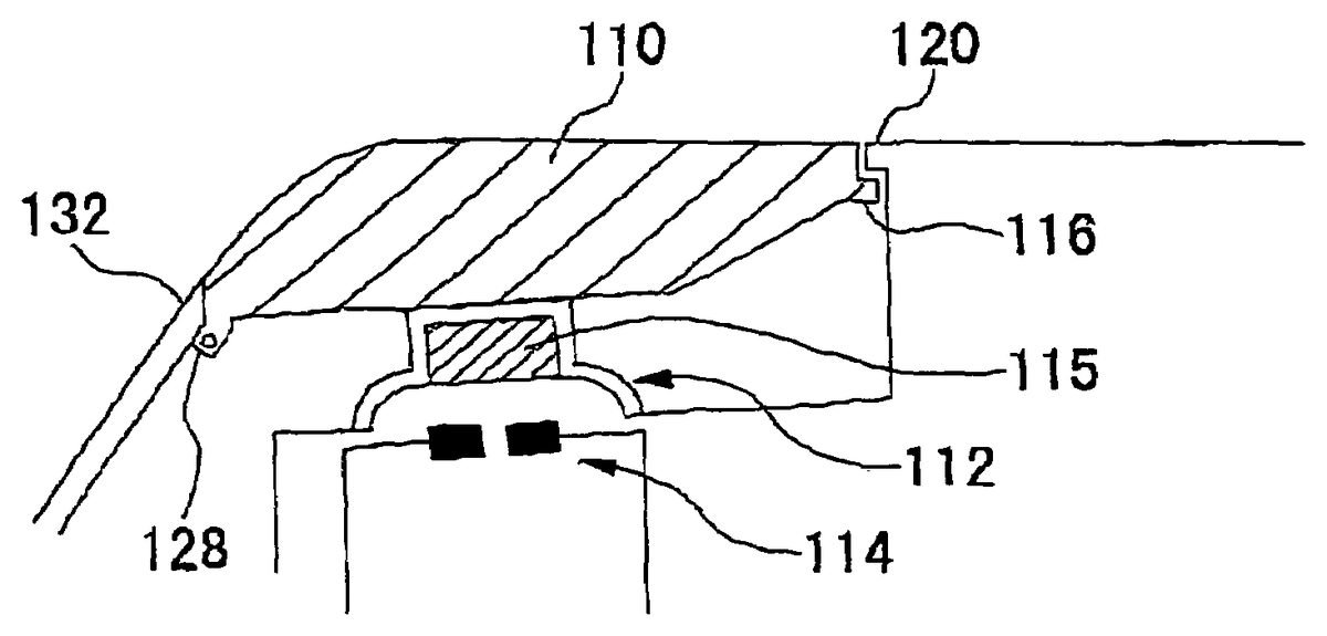
FIGS. 11A and 11Bare views showing the second example of the structure of the LR-buttons46. Again, although only the L-button46L is described herein, the R-button46R is horizontally symmetrical to the L-button46L and has the same structure. As shown inFIG. 11B, the L-button46L includes: the elongated button body110, the deformation member112, the conductive member115, and the switch contacts114, same as shown inFIG. 9B. The deformation member112is provided so as to be opposed to the back of the button body110. The conductive member115has conductivity, and is provided inside the deformation member112. The seizing means116and128are provided on both ends in a longitudinal direction of the button body110, respectively. Each of the seizing means116and128contacts against the inner side of the casing10so as to prevent the button body110from being detached from the casing10. The seizing means116and128have different shapes so as to contact against the corresponding receiving part120and132provided on the casing10, respectively. The first seizing means is a planar member116, which extends in a longitudinal direction as a flange from one end of the button body110with approximately same width as that of the button body110. The planar member116has a step descending regard to the pressed face by the user's finger. The second seizing means is a rod-like member128extending from the other end of the button body110in a direction approximately perpendicular to the longitudinal direction of the button body110. It is preferable that the rod-like member128is provided to extend from both sides of the button body110in a thickness direction as shown inFIG. 11A. However, the rod-like member128may be provided to extend only from either side. The structures and functions of the deformation member112, the conductive member115, and the switch contacts114are same with those of the first example.
The first and second seizing means are not required to have different shapes on both ends of the button body110. Alternatively, both first and second seizing means may be the above-described planar member, vertical part or rod-like member. The first and second seizing means may have other shapes as long as they have such a structure that the button body110can be prevented from being detached from the casing10.
FIGS. 12A,12B and12C are views showing the operation of the L-button46L according to the second example.FIG. 12Ashows an appearance where the user presses the left of the button body110, that is, the end on the edge side of the casing10. When the button body110is pressed, the step of the planar member116, corresponding to the first seizing means, comes into contact with receiving part120extending from the casing10to serve as a supporting point. The button body110slightly pivots about the supporting point in a direction indicated with an open arrow in FIG.12A to press down the deformation member112. At this time, the rod-like member128, corresponding to the second seizing means, is released from the inner side132of the casing10.
FIG. 12Bshows an appearance where the user presses the right of the button body110, that is, the end of the button body110closer to the center of the casing10. At this time, the rod-like member128, corresponding to the second seizing means, comes into contact with the inner side132of the casing10to serve as a supporting point. The button body110slightly pivots about the supporting point in a direction indicated with an open arrow inFIG. 12Bto press down the deformation member112. At this time, the planar member116, corresponding to the first seizing means, is released from the receiving part120extending from the casing10.
FIG. 12Cshows an appearance where the user presses the center of the button body110. At this time, both the planar member116and the rod-like member128are released from the receiving parts120and the inner side132of the casing10, respectively. The button body110moves downward to press the deformation member112.
As mentioned in the first and second examples, the LR-button is constituted to have a both-end supporting structure so that the operation of the button body is switched between pivoting about the right supporting point, pivoting about the left supporting point or moving vertically depending on the pressed position of the button body.
Although the position on the LR-buttons46that is easy to be pressed differs depending on the size of the hands and the finger lengths of the user gripping the casing10, an instruction can surely be input to the portable electronic device100even when any position of the button body110is pressed according to the LR-button structure of this embodiment. Therefore, the operability of the portable electronic device100is improved. In addition, even when any position of the button body110of the LR-button46is pressed, the user can feel a click of the LR-buttons because the LR-buttons moves downward by a certain distance when the user presses the button.
When a game creator conceives the game contents, he/she must take the operability of a controller into account. In this sense, the functions of the controller and the game contents are in close relation with each other. In other words, the game contents are often restricted by the functions or the operability of the controller. The portable electronic device according to this embodiment has the operation buttons including the arrow key, the analog device, the button keys, and the LR-buttons, which are equivalent to or superior to the functions of the controller of a stay-at-home type game machine although its size is compact. Since a conventional portable game machine is not equipped with various operation buttons, the feasible game contents are restricted or a game program is required to be changed when some stay-at-home type game is ported to the portable game machine. In the portable electronic device according to this embodiment, however, such problems do not arise. Thus, the sphere of creation by game creators can be expanded.
As described above, according to the present invention, the portable electronic device with high operability and extensibility can be provided in such a compact size casing that the user can grip with both hands.
The present invention has been described based on some embodiments. The above-described embodiments are merely exemplary. Thus, those skilled in the art would understand that various modifications are possible in combinations with the components and such modifications are within the scope of the present invention. Moreover, an arbitrary combination of the components described in the embodiments is also effective as an embodiment of the present invention.
The structure or the arrangement of the buttons according to the invention may be also applicable to a controller for a stay-at-home type game machine.
Claims
- An electronic device comprising: a casing having a display on its front face, ends of which being gripped by both hands of a user, said casing being comprised of a front face, a rear face and one or more side faces, the side faces including a top side face, a bottom side face, a left side face and a right side face;and at least one button operation means provided on the side face of said casing;said button operation means further comprising: an elongated button body, wherein said button body is operated by the user's forefinger or middle finger aligned with the longitudinal direction of said button body;a deformation member being pressed by a back of said button body when said button body is pressed down, the back being a flip side of a face pressed by the user;and switch contacts being electrically conducted due to the deformation of the deformation member;wherein a first seizing means is provided on a side of the button body close to a center of the casing, said first seizing means extending as a flange in a longitudinal direction;a second seizing means is provided on a side of the button body close to one of the left or right side faces of the casing, said second seizing means facing a section of the casing;wherein there is a clearance between each of said first and second seizing means and the inner wall of casing so that each of said first and second seizing means may contact against an inner wall of the casing to pivot about the contact point or alternatively may be disengageable toward an inside of the casing;when the side of the button body close to the side face of the casing is pressed, said first seizing means on the opposite side of the pressed side comes into contact with the inner wall of the casing to function as a pivot point, and said second seizing means on the pressed side disengages from the inner wall of the casing to pivot about the pivot point to the pressed direction;wherein the first and second seizing means are separated in the longitudinal direction of said button body, said first seizing means being a planar member extending in a longitudinal direction from one end of said button body with a step from the pressed face, and said second seizing means being a vertical part formed in another end of said button body;and wherein when said button body is not pressed, said step of the planar member is engaged with a corresponding receiving part extending from said casing and said vertical part comes into contact with the section of said casing.
- The electronic device according to claim 1 , wherein when a vicinity of center of said button body is pressed, both said first and second seizing means are disengaged from the inner wall of the casing and said button body moves downward.
- The electronic device according to claim 1 , wherein when any position of said button body is pressed, said deformation member is deformed in accordance with the pressed position to allow said switch contacts to be electrically conducted.
- The electronic device according to claim 1 , said deformation member being made of a rubber.
- The electronic device according to claim 1 , said button operation means being provided at a position where an operation by any one of a forefinger and a middle finger of the user is easy when said casing is gripped by the user.
- The electronic device according to claim 5 , said button operation means being provided in a notch formed on the side face of said casing.
- The electronic device according to claim 1 , wherein the surface of said first and second seizing means contacts against a limb of the opening of the casing so as to prevent the button body from being detached from the opening of the casing.
- The electronic device according to claim 1 , when the side of the button body close to the center of the casing is pressed, said second seizing means on the opposite side of the pressed side comes into contact with the inner wall of the casing to function as a pivot point, said first seizing means on the pressed side disengages from the inner wall of the casing to pivot about the pivot point to the pressed direction.
- A game controller comprising: a casing, ends of which being gripped by both hands of a user, said casing being comprised of a front face, a rear face and one or more side faces, the side faces including a top side face, a bottom side face, a left side face and a right side face;and at least one button operation means provided on the side face of said casing;said button operation means further comprising: an elongated button body wherein said button body is operated by the user's forefinger or middle finger aligned with the longitudinal direction of said button body;a deformation member being pressed by a back of said button body when said button body is pressed down, the back being a flip side of a face pressed by the user;and switch contacts being electrically conducted due to the deformation of the deformation member;wherein a first seizing means is provided on a side of the button body close to a center of the casing, said first seizing means extending as a flange in a longitudinal direction;a second seizing means is provided on a side of the button body close to one of the left or right side faces of the casing, said second seizing means facing a section of the casing;wherein there is a clearance between each of said first and second seizing means and the inner wall of casing so that each of said first and second seizing means may contact against an inner wall of the casing to pivot about the contact point or alternatively may be disengageable toward an inside of the casing;when the side of the button body close to the side face of the casing is pressed, said first seizing means on the opposite side of the pressed side comes into contact with the inner wall of the casing to function as a pivot point, and said second seizing means on the pressed side disengages from the inner wall of the casing to pivot about the pivot point to the pressed direction;wherein the first and second seizing means are separated in the longitudinal direction of said button body, said first seizing means being a planar member extending in a longitudinal direction from one end of said button body with a step from the pressed face, and said second seizing means being a vertical part formed in another end of said button body;and wherein when said button body is not pressed, said step of the planar member is engaged with a corresponding receiving part extending from said casing and said vertical part comes into contact with the section of said casing.
- The game controller according to claim 9 , wherein when a vicinity of a center of said button body is pressed, both said first and second seizing means are disengaged from the inner wall of the casing and said button body moves downward.
- The game controller according to claim 9 , wherein when any position of said button body is pressed, said deformation member is deformed in accordance with the pressed position to allow said switch contacts to be electrically conducted.
- The game controller according to claim 9 , said deformation member being made of a rubber.
- The game controller according to claim 9 , said button operation means being provided at a position where an operation by any one of a forefinger and a middle finger of the user is easy when said casing is gripped by the user.
- The game controller according to claim 13 , said button operation means being provided in a notch formed on the side face of said casing.
- The electronic device according to claim 9 , when the side of the button body close to the center of the casing is pressed, said second seizing means on the opposite side of the pressed side comes into contact with the inner wall of the casing to function as a pivot point, said first seizing means on the pressed side disengages from the inner wall of the casing to pivot about the pivot point to the pressed direction.
Disclaimer: Data collected from the USPTO and may be malformed, incomplete, and/or otherwise inaccurate.