U.S. Pat. No. 7,618,322
GAME SYSTEM, STORAGE MEDIUM STORING GAME PROGRAM, AND GAME CONTROLLING METHOD
AssigneeNintendo Co., Ltd.
Issue DateMay 6, 2005
U.S. Patent No. 7,618,322: Game system, storage medium storing game program, and game controlling method

Summary:
The ‘322 patent describes a game with a controller with an operation surface that produces an audible percussive sound when subjected to a physical impact. The controller generates audible sounds in response to an elastic deformation of the striking surface. The sounds are generated whenever a player beats on the controller and the game process is changed depending on the volume (determined by how hard the strike is) value of the operation sound.
Abstract:
A game system includes a game apparatus, and the game apparatus is connected with a monitor and a percussion-type controller. When a game player beats a first beating operation surface or a second beating operation surface, first operation data is input from the controller to the game apparatus. Furthermore, when a microphone detects an operation sound generated at a time that a beating operation is performed, second operation data including volume data is input from the controller to the game apparatus. In the game apparatus, when a magnitude of the volume data is equal to or more than the predetermined threshold value, an ability value as to an action of the player object to be executed according to a command indicated by the first operation data is changed to execute the action.
Illustrative Claim:
1. A game system for displaying a game image including a player object operable by a player on a display apparatus, comprising: a controller device having an operation surface that produces an audible percussive sound when subjected to a physical impact, said controller also generating an operation data input signal in response to an elastic deformation of said surface by a physical impact; operation data detector programmed logic circuitry configured to detect one or more operation data input signals generated by said controller device in response to a beating of said operation surface of said controller device by said player; an audible sound detector that detects one or more audible percussive sounds produced by said beating upon the operation surface of the controller or by other audible percutient player actions; volume value determining programmed logic circuitry configured to determine a volume level value for an audible percussive sound detected by said sound detector; and game processing programmed logic circuitry configured to change a game process in response to an operation data input signal when both an operation data input signal and an audible percussive sound are detected as occurring together within a predetermined time period.
Illustrative Figure
Abstract
A game system includes a game apparatus, and the game apparatus is connected with a monitor and a percussion-type controller. When a game player beats a first beating operation surface or a second beating operation surface, first operation data is input from the controller to the game apparatus. Furthermore, when a microphone detects an operation sound generated at a time that a beating operation is performed, second operation data including volume data is input from the controller to the game apparatus. In the game apparatus, when a magnitude of the volume data is equal to or more than the predetermined threshold value, an ability value as to an action of the player object to be executed according to a command indicated by the first operation data is changed to execute the action.
Description
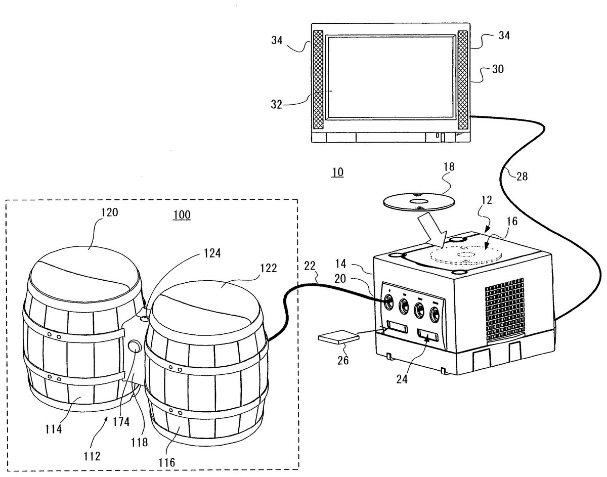
DETAILED DESCRIPTION OF THE PREFERRED EMBODIMENTS Referring toFIG. 1, an exemplary video game system10includes a video game apparatus12. The video game apparatus12includes an approximately cubic housing14, and the housing14is provided with an optical disk drive16on an upper edge thereof. An optical disk18which is one example of an information storage medium such as CD-ROM, DVD-ROM for storing a game program, etc. is loaded on the optical disk drive16. The housing14is provided with a plurality of connectors20(four in this illustrative implementation) on a front surface thereof. These connectors20are for connecting a controller100to the video game apparatus12by a cable22, and can connect up to the four controllers100to the video game apparatus12in this example implementation. It is noted that the controller100is connected to the video game apparatus12by the cable22in this illustrative example. However, the controller100may be connected to the video game apparatus12by another method such as a wireless manner via an electromagnetic wave (e.g., radio wave or infrared ray). At least one (two in this example) memory slot24is provided below the connectors20on the front surface of the housing14of the video game apparatus12. A memory card26is inserted to this memory slot24. The memory card26is utilized for loading the game program and etc. read from the optical disk18so as to temporarily store it, or storing (saving) game data (e.g., result of a game) of the game that the player plays by utilizing the game system10. On a rear surface of the housing14of the video game apparatus12, an AV cable connector (not shown) is provided, and by utilizing the connector, a monitor30is connected to the video game apparatus12through an AV cable28. The monitor30is typically a color television receiver, and the AV cable28inputs a video signal from the video game apparatus12to a video input terminal of the color television, and applies a sound signal to a sound input ...
DETAILED DESCRIPTION OF THE PREFERRED EMBODIMENTS
Referring toFIG. 1, an exemplary video game system10includes a video game apparatus12. The video game apparatus12includes an approximately cubic housing14, and the housing14is provided with an optical disk drive16on an upper edge thereof. An optical disk18which is one example of an information storage medium such as CD-ROM, DVD-ROM for storing a game program, etc. is loaded on the optical disk drive16. The housing14is provided with a plurality of connectors20(four in this illustrative implementation) on a front surface thereof. These connectors20are for connecting a controller100to the video game apparatus12by a cable22, and can connect up to the four controllers100to the video game apparatus12in this example implementation.
It is noted that the controller100is connected to the video game apparatus12by the cable22in this illustrative example. However, the controller100may be connected to the video game apparatus12by another method such as a wireless manner via an electromagnetic wave (e.g., radio wave or infrared ray).
At least one (two in this example) memory slot24is provided below the connectors20on the front surface of the housing14of the video game apparatus12. A memory card26is inserted to this memory slot24. The memory card26is utilized for loading the game program and etc. read from the optical disk18so as to temporarily store it, or storing (saving) game data (e.g., result of a game) of the game that the player plays by utilizing the game system10.
On a rear surface of the housing14of the video game apparatus12, an AV cable connector (not shown) is provided, and by utilizing the connector, a monitor30is connected to the video game apparatus12through an AV cable28. The monitor30is typically a color television receiver, and the AV cable28inputs a video signal from the video game apparatus12to a video input terminal of the color television, and applies a sound signal to a sound input terminal. Accordingly, a game image of a three-dimensional (3D) video game, for example, is displayed on a screen32of the color television (monitor)30. A game sound such as a game music, a sound effect and etc. is output from right and left speakers34, or in a case of causing a surround effect with two speakers, a game sound including a surround sound is output.
In the game system10, a user or a game player first turns on an electric power supply of the video game apparatus12in order to play a game (or another application), and then selects a suitable optical disk18storing a video game (or another application intended to play), and loads the optical disk18on the disk drive16of the video game apparatus12. In response thereto, the game apparatus12starts to execute the video game or another application on the basis of software stored in the optical disk18. The user operates the controller100for applying an input to the game apparatus12. In response thereto, the game or another application is started, and a moving image object (player object) can further be moved in different directions.
Here, referring toFIG. 1-FIG.5, the conga-type controller100of this example implementation is described in detail. The controller100includes a body112, and the body112consists of a first housing114in the form of a barrel, a second housing116having approximately the same size and the same shape as the first housing114, and a third housing118(connecting portion) that couples the first housing114and the second housing116and is formed in the form of quadratic prism (a rectangular parallelepiped) smaller than the first housing114and the second housing116.
Furthermore, on the upper surface (top surface) of the first housing114and the second housing116, covers120and122are respectively provided. The areas covered by the covers120and122are areas (operating areas) or operation surfaces to be subjected to an operation (beating operation) by a player or a user. That is, the operation apparatus or the controller100has two operation input surfaces on the upper surface of the first housing114and on the upper surface of the second housing116. For example, the covers120and122are made of rubber, and elastically deformed in shape according to a beating operation by the player or the user, and then restored to an original shape.
It is noted that as shown inFIG. 1, on the upper surface of the third housing3, a microphone124is provided. In a case of providing the hole for collecting sounds, the microphone124is set inside of the third housing118, or is set such that its sound collecting portion is exposed from the hole. It is noted that although the microphone124is provided on the third housing118in this example implementation, it may be provided on the first housing114or the second housing116except for its operating area to be operated by the user (operation input portion).
FIG. 2shows an exploded view of a part of the controller100. That is, this is an exploded view as to the first housing114, and for the sake of simplicity, this view is omitted as to the second housing116and the third housing118.
Referring toFIG. 2, the first housing114includes an upper (ceiling) surface panel126, and on the upper surface panel126, switch boards130and132having a different size are provided. These switch boards130and132are fixedly arranged (housed) at predetermined positions of the upper surface panel126. Although omitted inFIG. 2, each of the switch boards130and132has two contacts (only the contacts132a,132aof the switch board132are illustrated inFIG. 4andFIG. 5).
On each of the switch boards130and132, two rubber switches134are arranged, and the respective rubber switches134are joined to edges of depressing protrusions150and156described later. Although omitted inFIG. 2, on a rear surface of the rubber switch134, a contact134ais provided, and each rubber switch134is provided at a position opposed to each of the contacts of the switch boards130and132(seeFIG. 4).
On the respective rubber switches134, a lid136of the first housing114is provided, and this is attached on the first housing114so as to cover the upper surface panel126, the switch boards130,132, and the rubber switches134. The lid136is provided with six holes138that engaging protrusions148and154described later penetrate, and four holes140that the rubber switches134arranged at the positions opposed to the depressing protrusions150and156penetrate.
On the lid136, depressing members142and144having a different size (shape) are provided, and over this, the cover120to be attached to the lid136is further provided. As shown inFIG. 3andFIG. 4being a part of a cross-sectional view IV-IV ofFIG. 3, the depressing portion144has its main body152in the form of a crescent, and is provided with three engaging protrusions154and two depressing protrusions156that are downwardly protruded from the main body152. Furthermore, the depressing member142has its main body146in the form of a dichotomy, and is provided with three engaging protrusions148and two depressing protrusions150that are downwardly protruded from the main body146.
FIG. 3is a view when viewing the first housing114and the cover120from directly above. The engaging protrusions148, the depressing protrusions150, the engaging protrusions154and the depressing protrusions156are arranged at positions shown inFIG. 3. As understood fromFIG. 3, the three engaging protrusions148are provided at the edges (both right and left edges and lower edge) of the main body146of the depressing member142, and the two depressing protrusions150are provided between the three engaging protrusions148. Furthermore, the three engaging protrusions154are provided at the edges (both right and left edges and upper edge) of the main body152of the depressing member144, and the two depressing protrusions156are provided between the three engaging protrusions154. In addition, as shown inFIG. 4, the engaging protrusion154(this is true for the engaging protrusion148) penetrates the hole138on the lid136and the hole128on the upper surface panel126such that its engaging portion158provided at the tip end penetrates the upper surface panel126(the inside of the first housing114). It is noted that the lid136is attached to the upper surface panel126, and whereby, the holes128of the upper surface panel126are formed inside the holes138. Furthermore, the depressing protrusions150and the depressing protrusions156are provided so as to depress the rubber switches134arranged within the holes140of the lid136. That is, each of the rubber switches134is housed within the first housing114such that its surface (surface to be connected with the depressing protrusion150and the depressing protrusion156) is exposed from the hole140of the first housing114.
It is noted that the tip ends of the depressing protrusions150and156are arranged in such a manner as to be brought into contact with the rubber switches134as shown inFIG. 4. Or, these may be joined by a fitting structure or an adhesive or the both thereof. Accordingly, the depressing members142and144are supported by the rubber switches134.
In addition, as shown inFIG. 3andFIG. 4, the engaging protrusion154(it is true for the engaging protrusion148) is provided with a notch (slit)160, and thus, each of the engaging protrusions148and154is reduced in diameter when penetrating the hole128of the upper surface panel126, and then restored when having penetrated the hole128. Then, the engaging portion158is engaged with the rear surface (inner wall of the first housing114) of the upper surface panel126. This makes it possible to prevent the depressing members142and144from being disengaged.
For example, as shown inFIG. 5(A), when the player beats the right side of the controller100(cover120), the cover120is elastically changed, and then the right side of the depressing member144(this is also true for the depressing member142) is apt to be depressed. At this time, the engaging portion158of the engaging protrusion154provided at the left side of the depressing member144is engaged with the rear surface of the upper surface panel126. This makes it possible to prevent the depressing member144from being upwardly actuated. Accordingly, the depressing member144at the right side is downwardly actuated, and the rubber switch134at the right side is depressed by the depressing member156so as to be brought into contact with the switch board132. That is, the contact132aand the contact134aare brought into contact with each other.
Furthermore, as shown inFIG. 5(B), when the player beats the left side of the controller100(cover120), the cover120is elastically changed, and the left side of the depressing member144(this is also true for the depressing member142) is apt to be depressed. At this time, the engaging portion158of the engaging protrusion152provided at the right side of the depressing member144is engaged with the rear surface of the upper surface panel126. This makes it possible to prevent the depressing member144from being upwardly actuated. Accordingly, when the depressing member144at the left side is downwardly actuated, the rubber switch134at the left side is depressed by the depressing member156so as to bring the contact134aof the rubber switch134into contact with the contact132aof the switch board132.
That is, even if the depressing member144(this is also true for the depressing member142) is beaten at any position (area), at least one engaging portion158of the engaging protrusion154(148) except for the engaging protrusion154(148) provided at the beaten area or in proximity thereto is engaged with the rear surface of the upper surface panel126. Due to this, when a beating operation by the player is present, the depressing member144(142) is depressed, a contact134aof any rubber switch134is sure to be brought into contact with the contact132aof the switch board132(contact of the switch board130).
More specifically, when the left half area of the controller100(cover120) shown inFIG. 5is beaten at any position, the engaging portion158of the engaging protrusion154at the right side of the depressing member144is engaged with the rear surface of the upper surface panel126, the left side of the depressing member144is downwardly actuated, the rubber switch134at the left side is depressed by the depressing member156, and the contact134aof the rubber switch134is brought into contact with the contact132aof the switch board132at the left side. On the contrary thereto, when the right half area of the controller100(cover120) is beaten at any position, the engaging portion158of the engaging protrusion154at the left side of the depressing member144is engaged with the rear surface of the upper surface panel126, the right side of the depressing member144is downwardly actuated, the rubber switch134at the right side is depressed by the depressing member156, and the contact134aof the rubber switch134is brought into contact with the contact132aof the switch board132at the right side. Furthermore, when the center area of the controller100(cover120) is beaten at any position, the depressing member144is approximately uniformly depressed at both the right and left sides, the rubber switches134at the right and the left sides are depressed by the depressing members156, and thus, both of the contacts134aof the rubber switches134are brought into contact with the contacts132aof the switch boards132.
Thus, even if the controller100(cover120) is beaten at any place (area), any one of the rubber switches is sure to be depressed to output the same operation signal.
FIG. 6shows an electric configuration of the controller100. Referring toFIG. 6, the controller100includes a controller IC162, and the controller IC162is connected with a first button164, a second button166, a third button168, and a fourth button170. As shown inFIG. 1, the cable22is inserted into the connector20of the game apparatus12, and whereby, the controller IC162is electrically connected to the game apparatus12as shown inFIG. 6. Furthermore, the controller IC162is connected with the microphone124via an operational amplifier172.
The first button164and the second button166are provided within the first housing114. In this example implementation, the first button164consists of the switch board130and the two rubber switches134provided on the switch board130(being opposed thereto). The second button166consists of the switch board132and the two rubber switches134provided to be opposed to the switch board132.
The third button168and the fourth button170are provided within the second housing116. In this example implementation, the third button168is constructed similarly to the first button164, and the fourth button170is constructed similarly to the second button166.
Thus, in this controller100, the player can perform various operations by use of any one of the first button164-the fourth button170or a combination of two or more thereof. The beating operation by the player is input to the controller IC162as a state signal indicative of an on/off state of the first button164-the fourth button170. Then, an operation signal corresponding to the beating operation is output to the game apparatus12from the controller IC162.
In the controller100, a sound (operation sound) generated by the player through a beating operation on the cover120and/or cover122, that is, the beating operation surface is input to the microphone124, amplified in the operational amplifier172, and then, input to the controller IC162. Thus, the operation signal according to the generation of the operation sound is output from the controller IC162to the game apparatus12. It is noted that in order to discriminate an operation sound from a noise, when the volume of the operation sound is equal to or more than the predetermined threshold value, it is detected that the sound input is present.
In this example implementation, although an operation signal generated through a beating operation of the beating surface is detected by the microphone124, it may be possible that depending on the kind of the game, a sound, a clapping generated by the player is detected.
FIG. 7shows one example of a format of the operation signal (operation data) output from the controller IC162to the game apparatus12. It is noted that the operation signal has a format corresponding to a standard controller of the game apparatus12(“GAME CUBE (trade name)” that is manufactured/marketed by the assignee of this application). Although not illustrated, the controller is provided with two analog joysticks (control stick and C stick), a cross key, an A button, a B button, an X button, a Y button, a Z button, an L trigger button, an R trigger button, and a START/PAUSE button, and so on.
As understood fromFIG. 7, the operation signal or operation data consists of 8 bytes. As to the first byte (1st byte), data of “0”, “0”, “ORG_CH”, “START”, “Y”, “X”, “B”, and “A” are written to bit7(b7) to bit0(b0), respectively. The bit7and the bit6are fixed values of “0”, and to the bit5, the data indicative of an on/off state of the setting mode “ORG_CH” is written. In this example implementation, if the setting mode “ORG_CH” is turned on, “1” is written, and if the setting mode “ORG_CH” is turned off, “0” is written. Here, the “ORG_CH” is a variable for setting a mode (setting mode) determining whether or not a standard position (original point (neutral position) of the joystick) is reset. Into the bit4-the bit0, data indicative of an on/off state of the START button, the Y button, the X button, the B button, and the A button are respectively written. In this example implementation, if the button is turned on, “1” is written to the relevant bit, and if the button is turned off, “0” is written to the relevant bit.
As to the second byte (2nd byte), data of “FIN”, “L”, “R”, “Z”, “UP”, “DOWN”, “RIGHT”, and “LEFT” are written to bit7(b7)-bit0(b0), respectively. Into the bit7, data indicative of an on/off state of a mode “FIN” for identifying a controller is written. In this example implementation, in a case of a standard controller, “1” is written, and in a case of the controller100(percussion type controller), “0” is written. Into the bit6-the bit0, data indicative of an on/off state of the L trigger button, the R trigger button, the Z button, the UP button, the DOWN button, the RIGHT button, and the LEFT button are respectively written. The data values to be written to the respective bits are the same as in the above-described Y button, and so on.
It is noted that the UP button, the DOWN button, the RIGHT button, and the LEFT button correspond to the respective buttons of the cross key.
To the third byte (3rd byte), data indicative of an amount of inclination of the control stick toward an X direction is written by binary data utilizing 8 bits in all. Accordingly, the inclination toward the X direction is represented by numerals in the “00000000” (“0” in a decimal numeral)-“11111111” (“255”) range. For example, if the control stick is inclined to the left, it is close to “0”, and if the control stick is inclined to the right, it is close to “255”.
It is noted that in a default setting, the neutral position is represented by “128 (01000000)”, and if the value is smaller than this, it is shown that the control stick is inclined toward the left direction, and if the value is greater than this, it is shown that the control stick is inclined toward the right direction. The amount of the inclination can be detected by a difference between the obtained data value and the data value at the neutral position.
To the fourth byte (4th byte), data indicative of an amount of inclination of the control stick toward the Y direction is written by binary data utilizing 8 bits in all. Accordingly, the inclination toward the Y direction is also represented by the numerals in the “00000000” (“0” in a decimal numeral) to “11111111” (“255”) range. For example, if the control stick is downwardly inclined, the value is close to “0”, and if the control stick is upwardly inclined, the value is close to “255”.
It is noted that in a default setting, the neutral position is represented by “128 (01000000)”, and if the value is smaller than this, it is shown that the control stick is downwardly inclined, and if the value is greater than this, it is shown that the control stick is upwardly inclined. The amount of the inclination can be detected by a difference between the obtained data value and the data value at the neutral position.
To the fifth byte (5th byte), data indicative of an amount of inclination of the C stick toward the X direction is written by binary data utilizing 8 bits in all. Furthermore, to the sixth byte (6th byte), data indicative of an amount of inclination of the C stick toward the Y direction is written by binary data utilizing 8 bits in all. These data value is decided similarly to the above-described control stick.
To the seventh byte (7th byte), data indicative of an amount of the depression of the L trigger button is written by binary data utilizing 8 bits in all. The data value when the L trigger button is not depressed is “00000000”, and the data value is rendered greater in accordance with the amount of the depression. That is, the data value when depressed at the maximum is “11111111”.
To the eighth byte (8th byte), data indicative of an amount of the depression of the R trigger button is written by binary data utilizing 8 bits in all. The data value is decided similarly to the above-described L trigger button.
The format of the operation signal is shown like this. The controller100is not provided with the joystick, the Y button, the X button, the B button, and the A button, but outputs to the game apparatus12an operation signal indicative of an on/off state of the first button164-the fourth button170, an operation signal in response to a generation of the sound to the microphone124, volume data of an operation signal, and a controller identifying mode, and therefore, the data of the first byte to the third byte are utilized, for example. More specifically, with respect to the first byte, data indicative of an on/off state of the first button164is written to the bit3, data indicative of an on/off state of the second button166is written to the bit2, data indicative of an on/off state of the third button168is written to the bit1, and data indicative of an on/off state of the fourth button170is written to the bit0. Furthermore, data “0” for identifying the controller100(percussion type controller) is written to the bit7of the second byte. In addition, data indicative of the presence or absence (on/off) of a sound input to the microphone124is written to the third byte. It is noted that in a case of outputting data of a volume (loudness) (volume data) to the game apparatus, the data value (“00000000”-“11111111”) corresponding to the volume is written to the third byte.
It is noted that as shown inFIG. 1, the controller100is provided with a START/PAUSE button174, and therefore, data indicative of an on/off state is written to the bit4of the first byte.
FIG. 8is a block diagram showing an electrical configuration of the video game system10ofFIG. 1example implementation. The video game apparatus12is provided with a central processing unit (hereinafter, may be referred to as “CPU”)36. The CPU36is called a computer or a processor, and is in charge of governing overall control of the video game apparatus12. The CPU36or the computer functions as a game processor, and is connected with a memory controller38via a bus. The memory controller38mainly controls writing to and reading from a main memory40connected via a bus under control of the CPU36. The memory controller38is coupled with a GPU (Graphics Processing Unit)42.
The GPU42forms a part of a rendering means, is constructed by a single chip ASIC, for example, and receives a graphics command (a construction command) from the CPU36via the memory controller38and then, in response to the command, generates the three-dimensional (3D) game image by a geometry unit44and a rendering unit46. Specifically, the geometry unit44performs a coordinate operation process such as turn-around or rotation, movement, transformation and etc. of a variety of characters and objects (which is formed by a plurality of polygons, and the polygon is a polygonal plane defined by at least three vertex coordinates) in a three-dimensional coordinates system. The rendering unit46performs an image generating process such as pasting a texture (pattern image) on each of polygons of the variety of objects, and so on. Accordingly, three-dimensional image data to be displayed on the game screen is produced by the GPU42, and the image data is rendered (stored) in the frame buffer48.
It is noted that data (primitive, polygon, texture and etc.) required for executing the construction command by the GPU42is acquired from the main memory40via the memory controller38.
The frame buffer48is a memory for rendering (storing) one frame of image data of the raster scan monitor30, for example, and is rewritten by the GPU42every frame. A video I/F58described later reads the data stored in the frame buffer48via the memory controller38, and whereby the 3D game image is displayed on the screen of the monitor30.
Furthermore, a Z buffer50has a storage capacity equal to the number of pixels (storing positions or addresses) corresponding to the frame buffer48×the number of bits of depth data per one pixel, and stores depth information or depth data (Z value) of dots corresponding to respective storing positions of the frame buffer48.
It is noted that the frame buffer48and the Z buffer50may be constructed by utilizing a part of the main memory40, or may be provided inside the GPU42.
The memory controller38is also connected to an ARAM54via a DSP (Digital Signal Processor)52. Accordingly, the memory controller38controls writing to and/or reading from the ARAM54as a sub memory in addition to the main memory40.
The DSP52functions as a sound processor, and generates audio data corresponding to a sound required for the game (effective sound), a sound, or music (BGM) by use of sound wave form data (not illustrated) written to the ARAM54.
The memory controller38is further connected to respective interfaces (I/F)56,58,60,62and64by buses. The controller I/F56is an interface for the controller100, and applies an operation signal or data from the controller IC162(FIG. 6) of the controller100to the CPU36through the memory controller38. The video I/F58accesses the frame buffer48to read the image data formed by the GPU42, and applies the image signal or the image data (digital RGB pixel values) to the monitor30via the AV cable28(FIG. 1).
The external memory I/F60makes the memory card26(FIG. 1) which is inserted into the front surface of the video game apparatus12communicate to the memory controller38. This allows the CPU36to write and read the data to and from the memory card26via the memory controller38. The audio I/F62receives audio data applied from the DSP52through the memory controller38or an audio stream read from the optical disk18, and then applies an audio signal (sound signal) corresponding thereto to the speaker34of the monitor30.
In addition, in a case of a stereo sound, the speaker34is provided at least one at left and right. Therefore, through a surround process, it is possible to hear a sound in a manner that the sound is generated from rear side of the player even if only two front left and right speakers are provided.
The disk I/F64connects the disk drive16to the memory controller38, and whereby the CPU36controls the disk drive16. The disk drive16writes the program data, the texture data and etc. read from the optical disk18to the main memory40under control of the CPU36.
As described above, when the player performs a beating operation on an operation surface of the controller100, at least any one of the first button164, the second button166, the third button168and the forth button170is operated, and operation data corresponding thereto (for the sake of explanation, refereed to be “first operation data”) is input to the video game apparatus12. Furthermore, an operation sound generated by the beating operation is detected by a microphone124, and operation data corresponding thereto (for the sake of explanation, “second operation data”) is input to the video game apparatus12. It is noted that the second operation data includes volume data of the operation sound.
For example, in the video game apparatus12, a game process (first game process) based on the first operation data and the second operation data is executed, and a game process (second game process) based on only the first operation data is executed. More specifically, in the video game apparatus12, when the first operation data is input, a game object (player object, for example) appearing in a virtual game executes an arbitrary action such as hitting, running, throwing, jumping, and so on according to a command indicated by the first operation data. In addition, in the video game apparatus12, an ability value of the player object as to the action to be executed according to the command indicated by the first operation data is changed on the basis of the second operation data.
In this example implementation, the volume data (volume value) included in the second operation data is detected, and the ability value of the player object is changed according to the magnitude of the volume value, that is, the difference of strength in beating operation. To describe it in detail, it is determined whether or not the volume value is equal to or more than a predetermined threshold value (different from the threshold value for determining whether the operation sound is input). If the volume value is equal to or more than the predetermined threshold value, an ability value as to an action to be executed according to the command indicated by the first operation data is changed (increased), and then, the action (first game process) is executed. Conversely, in a case that the volume value is less than the predetermined threshold value, the ability value as to an action to be executed according to the command indicated by the first operation data is not changed, and then, the action (second game process) is executed.
One example of the game process setting information in such a case is shown inFIG. 9. For example, if the action to be executed according to the command indicated by the first operation data is “punch”, when the first game process is executed, an offensive power as the ability value is “20”. The offensive power in a case of executing the second game process described later is “10”, and therefore, it can be understood that the offensive power is increased on the basis of the second operation data (volume data). Accordingly, as can be understood from one example of the game screen of the first game process as shown inFIG. 10(A), it is possible to destroy an object such as a stone (block) hindering the progress. On the other hand, when the second game process is executed on the basis of only the first operation data, the offensive power does not change (increase), and the current offensive power of the player object remains to be “10”. In this case, as can be understood from one example of the game screen of the second game process shown inFIG. 10(B), it is impossible to destroy the object such as a rock hindering the progress.
Furthermore, if the action to be executed according to the command indicated by the first operation data is “jump”, when the first game process is executed, the ability value of a jumping power becomes “30”. The jumping power is increased on the basis of the second operation data (volume data) similarly in a case where “punch” is an action. Accordingly, as can be understood from another example of the game screen of the first game process shown inFIG. 11(A), when the first game process is executed, the player object can move (jump) to a relatively higher place. On the other hand, when the second game process is executed on only the first operation data, the jumping power does not change (increase), and the current jumping power of the player object remains to be “15”. In this case, as can be understood from another example of the game screen of the second game process shown inFIG. 11(B), it is impossible to move to a relatively higher place.
It is noted that the game process and the game screen shown inFIG. 9-FIG.11are simple illustration, and it is worthy of notice that the ability value of the player object is changed on the basis of the second operation data (volume data).
More specifically, the CPU36shown inFIG. 8executes a game process according to a flowchart shown inFIG. 12. For example, when the player instructs a game start by operating the controller100, the CPU36starts a game process, and executes an initial setting in a step S1. Here, a work area and a buffer area of the main memory40are cleared. In a succeeding step S3, a game screen is displayed. For example, a game screen of a three-dimensional image including a player object, an enemy object, and another object is displayed.
In a step S5, an operation sound detecting process is executed. Here, it is detected whether or not the second operation data (including the volume data of the operation sound) according to the format shown inFIG. 7is input from the controller100. Next, in a step S7, a beating operation detecting process is executed. Here, it is detected whether or not the first operation data according to the format shown inFIG. 7is input from the controller100. It is noted that the processes in the steps S5and S7can be executed in a reversed order. That is, it is appropriate that the operation sound (second operation data) and the beating operation (first operation data) are detected in the process in the step S5and the step S7.
Then, in a step S9, it is determined whether or not both of the operation sound and the beating operation are detected within a predetermined time period (30 msec, for example). That is, it is determined whether or not a time period from the detection of the operation sound in the step S5to the detection of the beating operation in the step S7is within a predetermined time period. The reason why such the determination is made is that only the operation sound when generated through the beating operation is reflected on the game process. It is noted that both the steps S5and S7are executed in the reverse order, and therefore, one of the operation sound and the beating operation is detected, and then, whether or not the other is detected within the predetermined time period is determined.
If “YES” in the step S9, that is, if the both of the operation sound and the beating operation are detected within the predetermined time period, a volume value detecting process is executed in a step S11. Here, a data value (“00000000”-“111111111”) of the volume data included in the second operation data as to the operation sound is detected. Next, in a step S13, it is determined whether or not the volume value, that is, the data value of the volume data is equal to or more than a threshold value (“01000000” in this example implementation). If “NO” in the step S13, that is, if the volume value is less than the threshold value, it is determined that the second operation data is not reflected on the ability value, and then, the process proceeds to a step S19.
On the other hand, if “YES” in the step S13, that is, if the volume value is equal to or more than the threshold value, by determining that the second operation data is reflected on the ability value, the first game process is executed on the basis of the first operation data and the second operation data in a step S15, and then, the process proceeds to a step S21. That is, in the step S15, the ability value as to an action to be executed according to the command indicated by the first operation data is increased, and then, the action is executed.
Furthermore, if “NO” in the step S9, that is, if both of the operation sound and the beating operation are not detected within the predetermined time period, it is determined whether or not only the beating operation, that is, the first operation data is detected in a step S17. If “NO” in the step S17, that is, if only the beating operation is not detected, the process directly proceeds to the step S21. On the other hand, if “YES” in the step S17, that is, if only the beating operation is detected, the second game process is executed on the basis of only the detected beating operation, that is, the first operation data in the step S19, and the process proceeds to the step S21. That is, in the step S19, without increasing the ability value as to an action to be executed according to the command indicated by the first operation data, the action is executed.
In the step S21, it is determined whether the game end or not. That is, it is determined whether an instruction of the game end is applied from the player, or the game is over. If “NO” in the step S21, that is, if it is not the game end, the process returns to the step S5. On the other hand, if “YES” in the step S21, that is, if it is the game end, the game process is ended.
According to this example implementation, the operation sound generated when a beating operation is performed on the controller is detected to reflect a loudness of the detected operation sound on the content of the game, and therefore, it is possible to change the content of the game depending on the difference of strength in operation by detecting the operation sound at a time of operating the controller.
It is noted that one threshold value is prepared to execute the first game process or the second game process according to the magnitude of the volume value in this illustrative implementation. However, it may be possible that two or more threshold values are prepared to selectively execute different three or more game processes.
Furthermore, in this example implementation, in a case that the volume value is less than the threshold value, and in a case that only the beating operation is detected, the same second game process is executed. However, a different game process can be executed between a case where the volume value is less than the threshold value and a case where only the beating operation is detected.
In addition, in this example implementation, a description is made on a case that the beating operation and the operation sound are separately detected, but in some cases, one operation signal (operation data) includes the first operation data and the second operation data. In such a case, it may be said that the first operation data and the second operation data are detected within the predetermined period.
A game system10of another example implementation is the same as the above-described example implementation except for that the magnitude of the volume value is directly reflected on the game process, and therefore, a duplicated description will be omitted. That is, in the above-described example implementation, depending on whether or not the operation sound generated when a beating operation is performed is equal to or more than the threshold value, it is determined whether or not the game process is to be changed (S13, S15, S19inFIG. 12). However, in the other example implementation, the ability value of the player object is changed depending on the magnitude of the volume value. That is, a change amount of the ability value is determined on the basis of the volume value.
Describing in detail, when an operation sound simultaneously generated at a time of performing a beating operation on the controller100is detected, the volume value of the operation sound is detected to determine the change amount of the ability value according to the volume value. Here, the data value of the volume is a value between “00000000”-“111111111”, and therefore, a maximum value of the change amount of the ability value is determined, and by multiplying the maximum value of the change amount by the ratio of the data value (volume value) of the detected volume to the maximum value of the data value of the volume, the change amount of the ability value is obtained. Then, at a time of executing the first game process, the change amount is added to the ability value.
Furthermore, by representing the change amount in a negative numerical value, it is possible to decrease the ability value. For example, the data value of the volume is divided into “00000000”-“00111111” and “01000000”-“11111111”. Then, in a case that the data value of the volume is equal to or less than “00111111”, the change amount is determined such that the smaller the data value is, the larger the change amount being a negative numerical value is. On the other hand, in a case that the data value of the volume is equal to or more than “01000000”, the change amount is determined such that the larger the data value is, the larger the change amount being the positive numerical value is. Thus, when the first game process is executed, the change amount is added to the ability value to allow the ability value to be increased or decreased.
In addition, a change amount of the ability value may be assigned to each of the data value of the volume “00000000”-“11111111”, and a change amount corresponding to the detected data value (volume value) of the volume may be added to the ability value.
It is noted that these are only illustrative examples, and it is worthy of notice that data value of the volume itself may be reflected on the ability value.
More specifically, the CPU36executes a game process according to a flowchart shown inFIG. 13. It is noted that the flowchart of the game process shown inFIG. 13is approximately the same as the flowchart of the game process shown inFIG. 12, and therefore, the same reference numerals are applied to the same processes. Furthermore, a description as to the same process will be omitted.
Referring toFIG. 13, the flowchart of the game process is different from the flowchart of the game process inFIG. 12in that the step S13inFIG. 12is deleted, and the process in the step S15is modified to the process in a step S15′, and the both flowcharts are the same except for that.
That is, when both of the operation sound and the beating operation are detected within the predetermined period (“YES” in the step S9), the volume value is detected in the step S11, and then, the process proceeds to the step S15′. In the step S15′, the change amount of the ability value is determined on the basis of the detected volume value, and the game process (first game process) in which the ability value of the player object is changed with the determined change amount is executed.
In another example illustrative implementation also, it is possible to change the content of the game depending on the difference of strength in operation by detecting the operation sound at a time of operating the controller.
Although the present invention has been described and illustrated in detail, it is clearly understood that the same is by way of illustration and example only and is not to be taken by way of limitation, the spirit and scope of the present invention being limited only by the terms of the appended claims.
Claims
- A game system for displaying a game image including a player object operable by a player on a display apparatus, comprising: a controller device having an operation surface that produces an audible percussive sound when subjected to a physical impact, said controller also generating an operation data input signal in response to an elastic deformation of said surface by a physical impact;operation data detector programmed logic circuitry configured to detect one or more operation data input signals generated by said controller device in response to a beating of said operation surface of said controller device by said player;an audible sound detector that detects one or more audible percussive sounds produced by said beating upon the operation surface of the controller or by other audible percutient player actions;volume value determining programmed logic circuitry configured to determine a volume level value for an audible percussive sound detected by said sound detector;and game processing programmed logic circuitry configured to change a game process in response to an operation data input signal when both an operation data input signal and an audible percussive sound are detected as occurring together within a predetermined time period.
- A game system according to claim 1 , wherein said game processing programmed logic circuitry performs a first game process in response to said operation data input signal when the volume value determined for a detected audible percussive sound is equal to or more than a predetermined value, and performs a second game process in response to said operation data when the volume value determined for said detected audible percussive sound is less than the predetermined value.
- A game system according to claim 2 , wherein said game processing programmed logic circuitry performs said second game process in response to said operation data input signal when only said operation data input signal is detected.
- A game system according to claim 2 , wherein said game processing programmed logic circuitry performs said first game process modified by said second game process when said operation data input signal and said audible percussive sound are detected within said predetermined time period, and the determined volume value of said audible percussive sound is equal to or more than the predetermined value.
- A game system according to claim 1 , wherein said game processing programmed logic circuitry changes an ability value of said player object based on the volume value determined by said volume value determining programmed logic circuitry.
- A game system according to claim 5 , wherein said first game process is performed based on a first ability value of said player object, and said second game process is performed based on a second ability value of said player object.
- A game system for displaying a game image including a player object operable by a player on a display apparatus, comprising: one or more controller devices having an operation surface that produce an audible percussive sound when subjected to a physical impact, said controller also generating an operation data input signal in response to an elastic deformation of said surface by a physical impact;operation data detector that detects one or more operation data input signals generated by a controller device in response to a beating of said operation surface of said controller device by said player;an audible sound detector that detects one or more audible percussive sounds produced by said beating upon the operation surface of the controller or by any other audible sound-producing percutient action by a player;and game processing programmed logic circuitry that performs a first game process in response to an operation data input signal when both of an operation data input signal and an audible percussive sound are detected within a predetermined time period, and performs a second game process in response to said operation data input signal when only said operation data input signal is detected within said predetermined time period.
- A computer-readable storage medium storing a game program executable by a computer of a game system that is provided with a controller device, the controller device to generate an input signal when an operation surface of said device is subjected to an elastic deformation, said surface to produce an audible percussive sound when subjected to a percutient action by a player, and said game system having a display apparatus that displays a game image including a game object operable by a player on a display apparatus using said controller, said game program causing a computer of said game system to perform operations of: detecting one or more operation data input signals, said operation data input signals generated by said controller in response to a percutient action which deforms the operational surface of said controller;detecting an audible sound generated by said percutient action to the operation surface of the controller by a player;determining a volume amplitude level of a detected audible sound generated by said percutient action, and generating a corresponding volume value of the detected audible sound;and changing a game process in response to detecting one or more of said operation data input signals depending on whether said generated volume value is greater than a predetermined volume value when both an operation data input signal and an audible sound generated by said percutient action to the controller operation surface are detected as occurring within a predetermined time period of each other.
- A computer-readable storage medium storing a game program executable by a computer of a game system that is provided with a controller device, the controller device to generate an input signal when an operation surface of said device is subjected to an elastic deformation, said surface to produce an audible percussive sound when subjected to a percutient action by a player, and said game system having a display apparatus that displays a game image including a game object operable by a player using said controller, said game program causing a computer of said game system to perform operations of: detecting an operation data input signal generated by the controller in response to a percutient action which deforms the operational sin-face of said controller;detecting an audible sound generated by said percutient action to the operation surface of said controller by a player;and performing a first game process when both of said operation data impact signal and an audible percussive sound produced by said percutient action are detected as occurring within a predetermined time of each other, and performing a second game process when only said operation data input signal is detected within said predetermined time.
- A method of controlling progress of a game played on a computer controlled game system that is provided with a controller device, the controller device to generate a data input signal to said computer when an operation surface of said device is subjected to an elastic deformation and wherein said surface produces an audible percussive sound when subjected to a percutient action by a player, and said game system having a display apparatus that displays a game image including a player object operable by a player using said controller device, comprising: detecting one or more operation data input signals, said signals generated by the controller device in response to a percutient action performed by a player which causes a deformation of the operation surface of the controller, detecting an audible percussive sound produced by said percutient action to the operation surface of the controller;determining a volume value of a detected audible percussive sound, and changing a game process based on said operation data input signal depending on a volume value determined when both of said operation data input signal and said audible percussive sound are detected as occurring within a predetermined time period of each other.
- A method of controlling progress of a game played on a computer controlled game system that is provided with a controller device, the controller device to generate a data input signal to said computer when an operation surface of said device is subjected to an elastic deformation and wherein said surface produces an audible percussive sound when subjected to a percutient action by a player, and said game system having a display apparatus that displays a game image including a player object operable by a player using said controller device, comprising: detecting an operation data input signal, said signal generated by the controller device in response to a percutient action performed by a player which causes a deformation of the operation surface of said controller;detecting an audible percussive sound produced by a percutient action, and performing a first game process in response to said operation data input signal when both of said operation data input signal and said audible percussive sound are detected as occurring within a predetermined time of one another, and performing a second game process in response to said operation data input signal when only said operation data input signal is detected.
- The method of claim 11 , wherein an ability value of said player object is changed based on the determined volume value.
- The method of claim 12 , wherein said first game process is performed based on a first ability value of said player object, and said second game process is performed on a second ability value of said player object.
Disclaimer: Data collected from the USPTO and may be malformed, incomplete, and/or otherwise inaccurate.