U.S. Pat. No. 7,591,727
ROTATION STRUCTURE OF OPERATING MEMBER FOR GAME MACHINE, AND VIDEO GAME DEVICE
AssigneeKonami Corporation
Issue DateAugust 25, 2005
Illustrative Figure
Abstract
A game-machine operation-member rotation structure 3 is provided in which an operation member 31 attached to a rotation shaft 34 supported so as to rotate is turned right and left, including: a moving body 352 which protrudes in the radial direction of the rotation shaft 34, rotates together with the rotation shaft 34 and moves freely in the axial direction; a spiral guide 36 which is concentric with the rotation shaft 34 and moves the moving body 352 in the axial direction as the rotation shaft 34 rotates; and a stopper which is disposed on a movement locus of the moving body 352.
Description
BEST MODE FOR IMPLEMENTING THE INVENTION Hereinafter, an example of the embodiment of the present invention will be described usingFIG. 1toFIG. 9. FIG. 1is a perspective view of a video game apparatus using a dummy steering wheel according to an embodiment of the present invention, showing its external appearance. This video game apparatus displays a virtual automobile race in a game space which is performed by a player. It is configured by a game-machine body1and a driver's seat10in which a player sits down. They are united or semi-fixed to each other on both sides at their bottoms. The game-machine body1includes a console box1A, and at its upper part, a monitor2for displaying an image is provided opposite to the driver's seat10. In an operation panel below the monitor2, there is disposed a dummy steering portion3. A gear shift lever4is placed on the left of the dummy steering portion3. Besides, in the lower part of the game-machine body1, a brake pedal5and an accelerator pedal6are provided which simulate a brake pedal and an accelerator pedal so that a person can step on them. In the game-machine body1, a control portion7is embedded which includes a control substrate or the like and controls the progress (e.g., the display of an image) of an automobile-race game on a monitor screen. In the control portion7, an operation signal is inputted from the dummy steering portion3, the operation portion4, the brake pedal5and the accelerator pedal6. It processes those kinds of signals based on a predetermined game program, so that a game proceeds. FIG. 2is a perspective view of a dummy steering portion shown inFIG. 1, showing its whole part.FIG. 3is a side view of the dummy steering portion shown inFIG. 2. The dummy steering portion3includes a dummy steering wheel31, and a main shaft34which supports the dummy steering wheel31so ...
BEST MODE FOR IMPLEMENTING THE INVENTION
Hereinafter, an example of the embodiment of the present invention will be described usingFIG. 1toFIG. 9.
FIG. 1is a perspective view of a video game apparatus using a dummy steering wheel according to an embodiment of the present invention, showing its external appearance.
This video game apparatus displays a virtual automobile race in a game space which is performed by a player. It is configured by a game-machine body1and a driver's seat10in which a player sits down. They are united or semi-fixed to each other on both sides at their bottoms.
The game-machine body1includes a console box1A, and at its upper part, a monitor2for displaying an image is provided opposite to the driver's seat10. In an operation panel below the monitor2, there is disposed a dummy steering portion3. A gear shift lever4is placed on the left of the dummy steering portion3. Besides, in the lower part of the game-machine body1, a brake pedal5and an accelerator pedal6are provided which simulate a brake pedal and an accelerator pedal so that a person can step on them.
In the game-machine body1, a control portion7is embedded which includes a control substrate or the like and controls the progress (e.g., the display of an image) of an automobile-race game on a monitor screen. In the control portion7, an operation signal is inputted from the dummy steering portion3, the operation portion4, the brake pedal5and the accelerator pedal6. It processes those kinds of signals based on a predetermined game program, so that a game proceeds.
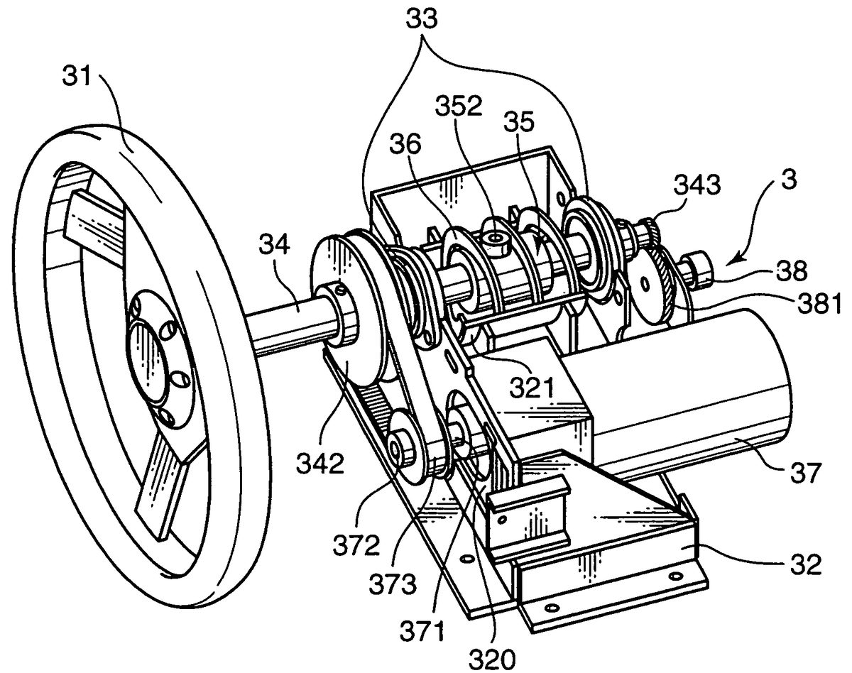
FIG. 2is a perspective view of a dummy steering portion shown inFIG. 1, showing its whole part.FIG. 3is a side view of the dummy steering portion shown inFIG. 2.
The dummy steering portion3includes a dummy steering wheel31, and a main shaft34which supports the dummy steering wheel31so that it can be turned. The dummy steering portion3is provided with a base32which has upright walls320that are opposite to each other in the depth directions. In the base32, bearings33are disposed at both upright walls. A main shaft34is supported so as to pass through these bearings33,33. On the main shaft34, a moving body35which has a predetermined length is fitted from outside between both bearings33. The relation between the main shaft34and the moving body35will be described with reference toFIGS. 4A and 4B.
FIGS. 4A and 4Bshow the relation between the main shaft34and the moving body35.FIG. 4Ais a partially longitudinal-sectional view.FIG. 4Bis a cross-sectional view (in a w-position). InFIGS. 4A and 4B, in the main shaft34, a groove331is formed at its substantially middle part. The groove331lies at a suitable place in the circumferential directions and has a predetermined length in the axial direction. The moving body35includes a cylindrical member350, and a key member351which protrudes at a proper place in the circumferential directions on the inner surface of the cylindrical member350. The key member351is attached by a screw or the like. This key member351is fitted into the groove331, so that the moving body35is united and rotated with the main shaft34. Besides, the key member351is set to be shorter than the groove331in the longitudinal directions. Thereby, the moving body35is designed to be able to move by a predetermined distance in the longitudinal directions over the formation region of the groove331. In addition, on the cylindrical member350, a protrusion body352which protrudes from the outer surface of the cylinder is fixed at a part in the circumferential directions and preferably substantially in the middle in the longitudinal directions. In this embodiment, the protrusion body352is formed by an upright shaft body3521, and a roller3522which can rotate around the shaft body3521. In the roller3522, at least its surface is made of, desirably, an elastic material.
InFIG. 2, a support plate portion321is disposed in the upper part of the base32. Besides, above this, a spiral guide member36is fixed at its peripheral edge on the support plate portion321. It has a helical shape and its axial center line lies in the main-shaft directions. The spiral guide member36is formed by processing a belt-shaped plate material into a helical shape. Its internal diameter is set to be fitted from outside on the cylindrical member350. In this embodiment, this spiral guide member36has a helix of substantially three rounds, so that the dummy steering wheel31can be turned up to an angle beyond at least one turn in the right and left directions. Besides, stoppers361a,361bjut out on the support plate portion321and at both ends of the spiral guide member36. The stoppers361a,361bare located to interfere in the turning orbit of the protrusion body352in the moving body35. Thereby, the protrusion body352is restrained from turning.
Specifically, as the main shaft34rotates, the protrusion body352in the moving body35is turned around the main shaft34. This turn causes itself to come into contact with and rub against the helical surface of the spiral guide member36(in this embodiment, the roller3522rolls and moves on the helical surface). Thereby, the moving body35is moved in the axial direction. Then, if the dummy steering wheel31is turned by a required angle, the protrusion body352comes into contact with the stopper361aor361bin the circumferential directions. Thereby, the dummy steering wheel31is kept from turning further. On the other hand, even if the dummy steering wheel31is turned in the opposite direction, then in the same way, it comes into contact with the stopper361aor361bat the other end. Thereby, it is restrained from turning beyond this.
Next to the support plate portion321(on the downside inFIG. 2) on the base32, a drive portion is fixed, for example, a motor37. It has a revolution shaft371which is parallel to the main shaft34or is directed toward this side. To the revolution shaft371, a pulley372is attached at its tip. To the main shaft34, a pulley342which has a required diameter is attached on the side of the dummy steering wheel31. Between the pulleys342and372, an endless belt373is stretched, so that a driving force from the motor37can be transmitted to the pulley342.
On the other hand, a gear343is attached to the depth-side end of the main shaft34. On the depth side of the base32, a variable resistor38is attached as a turning-angle detecting means. The variable resistor38includes a rotation shaft, and to this rotation shaft, a gear381is connected which engages with the gear343. Therefore, the rotation of the main shaft34is detected by the variable resistor38. As a result, the turning angle of the dummy steering wheel31can be detected. For example, when the dummy steering wheel31is in its neutral position or in the position so that the vehicle runs straight, an output voltage from the variable resistor38is set at 2.5V. The output voltage is also set to 0V when it is turned to the maximum in one direction, and it is set to 5V when it is turned to the maximum in the other direction. In that case, if an output voltage is detected from the variable resistor38, the position in which the dummy steering wheel31is turned can be detected. The motor37receives a detection result from the variable resistor38, and generates a torque so that the output voltage of the variable resistor38becomes 2.5V. Hence, a servo control system is configured. Besides, according to a right-and-left turning angle from the neutral position, control is executed so that a torque for generating a reaction force can be produced. This gives an operator a feeling that the operator is really driving when turning the dummy steering wheel31.
Next, a turning operation and a turn-restraint operation of the dummy steering wheel31will be described usingFIGS. 5 to 8.FIG. 5is a side view which corresponds toFIG. 3at the time when a dummy steering wheel is turned right to the maximum.FIG. 6is a sectional view (seen from the side of the dummy steering wheel31) of the dummy steering portion in a y-position shown inFIG. 5.
If an operator gives a right-turning force to the dummy steering wheel31in the neutral position shown inFIG. 3, the main shaft34is also rotated in the right direction. Together with the rotation of the main shaft34, the roller3522of the protrusion body352rolls in contact with the helical surface of the spiral guide member36. The protrusion body352(which is located in the middle of its movement locus in the neutral position) also moves along the helical surface. As the roller3522moves along the helical surface, the moving body35is moved along the groove331of the main shaft34in the direction apart from the dummy steering wheel31.
Then, the dummy steering wheel31is further turned rightward, the roller3522comes into contact with the stopper361band is restrained from rotating. This stopper361bon the depth side has a hollow contact surface which is fitted on the curved surface of the roller3522. To this hollow part, a rubber member3610is stuck as an elastic member.
Thereby, even if an operator attempts to turn the dummy steering wheel31beyond the right restraint position, the operator cannot turn the dummy steering wheel31. Besides, the roller3522comes into contact with the rubber member3610, thus preventing an impact from being given to the stopper361bwhen it comes into contact. In addition, the stopper361bhas the hollow shape so as to be fitted on the curved surface of the roller3522. This effectively prevents the stopper361bfrom being worn out in its part which comes into contact with the roller3522.
FIG. 7is a side view which corresponds toFIG. 3when the dummy steering wheel is turned leftward to the maximum.FIG. 8is a sectional view (seen from the side of the dummy steering wheel31) of the dummy steering portion in a z-position shown inFIG. 7.
If an operator gives a left-turning force to the dummy steering wheel31in the neutral position shown inFIG. 3, the main shaft34is also rotated in the left direction. Together with the rotation of the main shaft34, the roller3522of the protrusion body352rolls in contact with the helical surface of the spiral guide member36. The protrusion body352also moves along the helical surface. As the protrusion body352moves along the helical surface, the moving body35is moved along the groove331of the main shaft34in the direction of the dummy steering wheel31.
Then, the dummy steering wheel31is turned leftward, the roller3522comes into contact with the stopper361band is restrained from rotating. This stopper361aon the side of the dummy steering wheel31has a hollow left-hand surface which is fitted on the curved surface of the roller3522. The rubber member3610is stuck to this hollow part.
According to this configuration, even if an operator attempts to turn the dummy steering wheel31beyond the left restraint position, the operator cannot turn the dummy steering wheel31. In the video game apparatus according to this embodiment, according to the above described dummy steering portion3, the dummy steering wheel31can be moved by at least one right turn and one left turn from the neutral position.
If an operator turns the dummy steering wheel31, the turning angle of the dummy steering wheel31is detected by the variable resistor38. Then, the output voltage which corresponds to this turning angle is transferred to the control portion7. Based on this output voltage, the control portion7moves and displays an automobile virtually driven by the operator which is displayed in the monitor2. For example, if an output voltage of 2.5V is detected by the control portion7, the automobile is oriented forward and displayed. If an output voltage above 2.5V which indicates a right-turn angle is detected by the control portion7, the automobile is displayed so as to move rightward by the degree which corresponds to the turning angle. On the other hand, if an output voltage below 2.5V which indicates a left-turn angle is detected by the control portion7, the automobile is displayed in the monitor2so that it moves leftward by the degree which corresponds to the turning angle. Besides, if the operator releases the dummy steering wheel31after turning it from the neutral position, the motor37gives a rotating torque to the pulley342so that the output voltage of the variable resistor38becomes 2.5V. Thereby, the dummy steering wheel31is automatically returned to the neutral position. In addition, the motor37is adjusted so as to apply a predetermined torque in the direction opposite to the operator's turning direction and generate a reaction force required when the operator turns the dummy steering wheel31.
In this way, an operator turns the dummy steering wheel31, and thereby, a dummy automobile can be moved in an arbitrary direction. Therefore, a racing game is executed in which the operator drives on a winding racing course and competes to reach a goal point from a starting point ahead of others.
As described above, in the video game apparatus according to this embodiment, even if an operator turns the dummy steering wheel31up to a restraint position, the stoppers361a,361bcan bear an external force which is produced by a turning operation of the dummy steering wheel31in a radial direction (i.e., a turning direction of the dummy steering wheel31). Thereby, a direct restraint is place on the protrusion body352which can be turned together with the dummy steering wheel31. This eliminates a conventional disadvantage in that a spiral-structure part is worn out. Hence, the protrusion body352's contact with the stopper361aor361bis stably held. Thereby, despite an impact at the time when the protrusion body352comes into contact with the stopper361aor361b, their contact surfaces can be effectively prevented from being deformed. Therefore, even if the dummy steering wheel31is designed to be automatically restored to the neutral position, then without affecting a restoration control system, the dummy steering wheel31can be constantly returned with precision to the neutral position.
Furthermore, there is no need for a member which changes an external force which is given by an operator into an external force in the thrust directions. This helps reduce the production cost of a video game apparatus. Besides, by changing the position of the stopper361aor361b, or the length of the spiral guide member36, a turning angle at which the dummy steering wheel31is restrained from turning can be easily varied.
Especially, the present invention is applied to a case in which a dummy steering wheel is designed to be turned beyond one round, as is the case with the dummy steering portion3according to this embodiment. In such a case, according to the configuration of a spiral guide, a moving body and a stopper which is disposed on a movement locus of the moving body, the dummy steering wheel can be effectively restrained from turning.
Herein, the stoppers361a,361bare formed on both sides of the spiral guide member36. However, both stoppers361a,361bmay also be formed otherwise, as long as they are disposed on a movement locus of the protrusion body352and at an interval at the time when the protrusion body352turns by a predetermined number of rounds.
Moreover, the spiral guide member36is not necessarily a helical shape. Any other shapes are included, as long as it can lead the protrusion body352to turn and move in the axial direction of the main shaft34. Herein, the protrusion body352not necessarily includes the roller3522. The protrusion body352may also be a protrusion which can be guided and moved by the spiral guide member36.
Herein, the present invention is not limited to a structure in which the dummy steering wheel31is turned. It can be applied to a game-machine operation-member rotation structure which turns, at least forward and reversely, an operation member attached to a rotation shaft that is supported so as to rotate.
INDUSTRIAL APPLICABILITY
In the game-machine operation-member rotation structure according to the present invention, as an operator turns an operation member, a moving body rotates in the turning direction of the operation member, moves in the axial direction and comes into contact with a stopper. Therefore, an external-force load on the stopper becomes lighter than that in the thrust directions (i.e., the axial direction of a rotation shaft). Thereby, even if the operator turns the operation member by applying an excessive force shortly after the operation member is restrained from turning or after it is restrained, the operation member can be effectively prevented from turning further. This helps sufficiently prevent the stopper structure from being deformed and also helps stably hold the moving body's contact position with the stopper.
This application is based on Japanese Patent Application Serial No. 2003-0902 16, filed on Mar. 28, 2003, the contents of which are hereby incorporated by reference.
Claims
- A game-machine operation-member rotation structure comprising: a base which is provided stationary on said structure;an operation member rotatable right and left, the operation member being attached to a rotation shaft which is supported so as to rotate;a moving body having a protrusion which protrudes in the radial direction from the rotation shaft, the moving body and the protrusion rotating together with the rotation shaft and moving freely in an axial direction of the rotation shaft;a spiral guide which is provided fixed stationary to said base and concentric with the rotation shaft and moves the moving body in the axial direction as the rotation shaft rotates;and a stopper which is disposed on a movement locus of the moving body and is engaged by direct rotational displacement of the moving body by rotation of the rotation shaft.
- The game-machine operation-member rotation structure according to claim 1 , wherein at least the part of the stopper which comes into contact with the moving body is an elastic member.
- A video game apparatus, comprising: the game-machine operation-member rotation structure according to claim 1 , wherein the operation member is a dummy steering wheel for an automobile;and further comprising an image-display controlling means for moving a virtual vehicle in a game space as the dummy steering wheel is rotated.
- A game-machine operation-member rotation structure comprising: a base which is provided stationary on said structure;an operation member rotatable right and left, the operation member being attached to a rotation shaft which is supported so as to rotate;a moving body which protrudes in the radial direction from the rotation shaft, rotates together with the rotation shaft and moves freely in an axial direction of the rotation shaft;a spiral guide which is provided fixed stationary to said base and concentric with the rotation shaft and moves the moving body in the axial direction as the rotation shaft rotates;and a stopper which is disposed on a movement locus of the moving body and is engaged by direct rotational displacement of the moving body by rotation of the rotation shaft, wherein: the moving body has a cylindrical member which is fitted on the rotation shaft so that the cylindrical member slides freely, a key member which protrudes inward from the cylindrical member, and a protrusion portion which protrudes outward from the cylindrical member and slides on the spiral guide;the rotation shaft has a groove portion in the axial direction;and the key member is fitted into the groove portion so that the cylindrical member can move in the axial direction of the rotation shaft.
- The game-machine operation-member rotation structure according to claim 4 , wherein the protrusion portion is formed by a support shaft which stands in the radial direction, and a roller which is provided on the support shaft.
- A game-machine operation-member rotation structure, comprising: a base which is provided stationary on said structure;a rotation shaft rotatable supported on the base;an operation member which is attached to the rotation shaft and is rotatable by a user to right and left directions so as to rotate said rotation shaft;a movable assembly having a cylindrical member which is fitted on the rotation shaft so as to rotate together with the rotation shaft and to move freely on the rotation shaft in an axial direction of the rotation shaft;said movable assembly having a protrusion portion which protrudes radially outward from the cylindrical member and includes: a support shaft which extends in a radial direction of said rotation shaft;and a roller which is provided rotatably on said support shaft;a spiral guide provided stationary with respect to said base and concentric with said rotation shaft, said spiral guide being configured to guide the movable assembly to slide along said rotation shaft in the axial direction as the rotation shaft rotates said movable assembly so as to engage said roller in rotational contact with the spiral guide such that said engagement of said roller with said spiral guide displaces said movable assembly in said axial direction;and a stopper provided on said base which is in a movement locus of the protrusion portion of the movable assembly such that at least part of the stopper comes into contact with the protrusion portion by direct rotational displacement of the protrusion portion by rotation of the rotation shaft and the stopper is an elastic member and such that said stopper thereby restricts rotation of said rotation shaft.
- The game-machine operation-member rotation structure according to claim 6 , wherein: the cylindrical member has a key member which protrudes inward from the cylindrical member;the rotation shaft has a groove portion in the axial direction;and the key member is fitted into the groove portion so that the cylindrical member is movable in the axial direction of the rotation shaft.
- The game-machine operation-member rotation structure according to claim 6 , wherein at least the protrusion portion engages the stopper by rotational movement of the protrusion portion.
- The game-machine operation-member rotation structure according to claim 6 , wherein the stopper is fixed stationary on the base.
- A game-machine operation-member rotation structure, comprising: a base which is provided stationary on said structure;a rotation shaft rotatable supported on the base;an operation member which is attached to the rotation shaft and is rotatable by a user to right and left directions so as to rotate said rotation shaft;a movable assembly having a shaft mounted member which is fitted on the rotation shaft so as to rotate together with the rotation shaft and to move freely on the rotation shaft in an axial direction of the rotation shaft;said movable assembly having a protrusion portion which protrudes radially outward from the shaft mounted member;a spiral guide provided stationary with respect to said base and concentric with said rotation shaft, said spiral guide being configured to guide the movable assembly to slide along said rotation shaft in the axial direction as the rotation shaft rotates said movable assembly so as to engage said roller iii rotational contact with the spiral guide such that said engagement of said roller with said spiral guide displaces said movable assembly in said axial direction;and a stopper provided fixed relative to said spiral guide which is in a movement locus of the protrusion portion of the movable assembly such that at least part of the stopper comes into contact with the protrusion portion by direct rotational displacement of the protrusion portion by rotation of the rotation shaft and is an elastic member and such that said stopper thereby restricts rotation of said rotation shaft.
- The game-machine operation-member rotation structure according to claim 10 , wherein: the shaft mounted member has a key member which protrudes inward from the shaft mounted member;the rotation shaft has a groove portion in the axial direction;and the key member is fitted into the groove portion so that the shaft mounted member is movable in the axial direction of the rotation shaft.
- The game-machine operation-member rotation structure according to claim 10 , wherein at least the protrusion portion engages the stopper by rotational movement of the protrusion portion.
- The game-machine operation-member rotation structure according to claim 10 , wherein the stopper is fixed stationary on the base.
- The game-machine operation-member rotation structure according to claim 10 , wherein the movable assembly includes: a support shaft which extends in a radial direction of said rotation shaft;and a roller which is provided rotatably on said support shaft.
Disclaimer: Data collected from the USPTO and may be malformed, incomplete, and/or otherwise inaccurate.