U.S. Pat. No. 7,578,742
RECORDING MEDIUM STORING VIDEO GAME PROGRAM AND VIDEO GAME DEVICE
AssigneeNintendo Co., Ltd.
Issue DateMarch 23, 2005
Illustrative Figure
Abstract
The player gives a change in the input through a touch operation to a character pattern P2 displayed on a second display screen 12a covered by a touch panel. The character pattern P2 is associated with a player character P1 displayed on a first display screen 11a, and is displayed on a larger scale than the player character P1. The player character P1 is moved according to the change in the input. Thus, a video game is provided that is played on a dual-screen video game device with a novel operation in which the player can accurately specify an intended position.
Description
DESCRIPTION OF THE PREFERRED EMBODIMENTS First Embodiment A portable video game device including a computer for executing a video game program according to a first embodiment will now be described. While the present embodiment is directed to a case where the appearance of the player character included in the game image is changed, the appearance of the entire game image may alternatively be changed. A video game device of the present embodiment is a portable video game device including physically separate two display screens, one of which is covered by a touch panel. Alternatively, the video game device may be a home-console type video game device, an arcade video game device, a portable terminal device, a mobile telephone or a personal computer, for example. The video game device of the present invention may alternatively be a video game device including a single display screen that is divided by software into two screens, at least one of which is covered by a touch panel. FIG. 1generally shows a portable video game device1of the first embodiment. Referring toFIG. 1, the portable video game device1(hereinafter referred to simply as “the video game device1”) includes a first liquid crystal display device11(hereinafter a liquid crystal display device will be referred to as an “LCD”) having the first display screen11a, and a second LCD12having the second display screen12a. The surface of the second display screen12ais covered by the touch panel13. Provided on the right-hand side of the second display screen12aare an A button14a, a B button14band an R switch14c, which can be operated by the right hand of the player, and a speaker15for outputting game music and sound. Provided on the left-hand side of the second display screen12aare a cross-shaped control pad14d, a start button14e, a select button14fand an L switch14g, which can be operated by ...
DESCRIPTION OF THE PREFERRED EMBODIMENTS
First Embodiment
A portable video game device including a computer for executing a video game program according to a first embodiment will now be described. While the present embodiment is directed to a case where the appearance of the player character included in the game image is changed, the appearance of the entire game image may alternatively be changed. A video game device of the present embodiment is a portable video game device including physically separate two display screens, one of which is covered by a touch panel. Alternatively, the video game device may be a home-console type video game device, an arcade video game device, a portable terminal device, a mobile telephone or a personal computer, for example. The video game device of the present invention may alternatively be a video game device including a single display screen that is divided by software into two screens, at least one of which is covered by a touch panel.
FIG. 1generally shows a portable video game device1of the first embodiment. Referring toFIG. 1, the portable video game device1(hereinafter referred to simply as “the video game device1”) includes a first liquid crystal display device11(hereinafter a liquid crystal display device will be referred to as an “LCD”) having the first display screen11a, and a second LCD12having the second display screen12a. The surface of the second display screen12ais covered by the touch panel13. Provided on the right-hand side of the second display screen12aare an A button14a, a B button14band an R switch14c, which can be operated by the right hand of the player, and a speaker15for outputting game music and sound. Provided on the left-hand side of the second display screen12aare a cross-shaped control pad14d, a start button14e, a select button14fand an L switch14g, which can be operated by the left hand of the player. The A button14a, the B button14b, the R switch14c, the cross-shaped control pad14d, the start button14e, the select button14fand the L switch14gwill be collectively referred to as a control key14.
The video game device1also includes a stylus16for making an input to the touch panel13, and the stylus16is detachably accommodated in the video game device1. A game cartridge17storing a video game program of the present invention (hereinafter referred to simply as “the cartridge17”) is detachably attached to the video game device1. While it is effective to use the stylus16where the touch panel13has a high detection resolution, an input to the touch panel13may also be made by a finger of the player, for example, without using the stylus16where the touch panel13has a low detection resolution. The touch panel13may be any of various types of touch-sensitive panels, including a resistive film touch panel, an optical touch panel, an ultrasonic touch panel, a capacitance touch panel, an electromagnetic touch panel, etc. Particularly, a resistive film touch panel is inexpensive and advantageous. The detection method may be either a matrix method (digital) or a resistance detecting method (analog) depending on the configuration thereof.
FIG. 2is a block diagram showing a configuration of the video game device1. Referring toFIG. 2, the video game device1includes a CPU21being an example of a computer for executing a video game program. A WRAM (work memory device)22, a first GPU (graphics processing unit)23, a second GPU24and an I/F (interface) circuit25are electrically connected to the CPU (central processing unit)21via a predetermined bus. The WRAM22is a primary memory for storing the video game program to be executed by the CPU21and the results of a calculation performed by the CPU21. The first GPU23renders, in a first VRAM (video RAM)27, a first game image to be displayed on the first LCD11in response to an instruction from the CPU21, and the rendered first game image is displayed on the first display screen11aof the first LCD11. The second GPU24renders, in a second VRAM28, a second game image (graphic pattern) to be displayed on the second LCD12in response to an instruction from the CPU21, and the rendered second game image is displayed on the second display screen12a. The I/F circuit25is a circuit for exchanging data between the CPU21and external input/output devices such as the touch panel13, the control key14and the speaker15.
The touch panel13(including a touch panel device driver) has a coordinate system corresponding to that of the second VRAM28for outputting data of a coordinate position corresponding to a position that is input (specified) by the stylus16or a finger of the player. It is assumed in the present embodiment that the resolution of the display screen is 192 dots×256 dots and the detection resolution of the touch panel13is also 192 dots×256 dots. The detection resolution of the touch panel13may be lower than the resolution of the display screen.
A connector26is also electrically connected to the CPU21, and the cartridge17is detachably connected to the connector26. The cartridge17is a storage medium for storing a video game program. More specifically, the cartridge17includes a ROM17afor storing a video game program, and a RAM17bfor rewritably storing backup data. The video game program stored in the ROM17aof the cartridge17is loaded to the WRAM22, and executed by the CPU21.
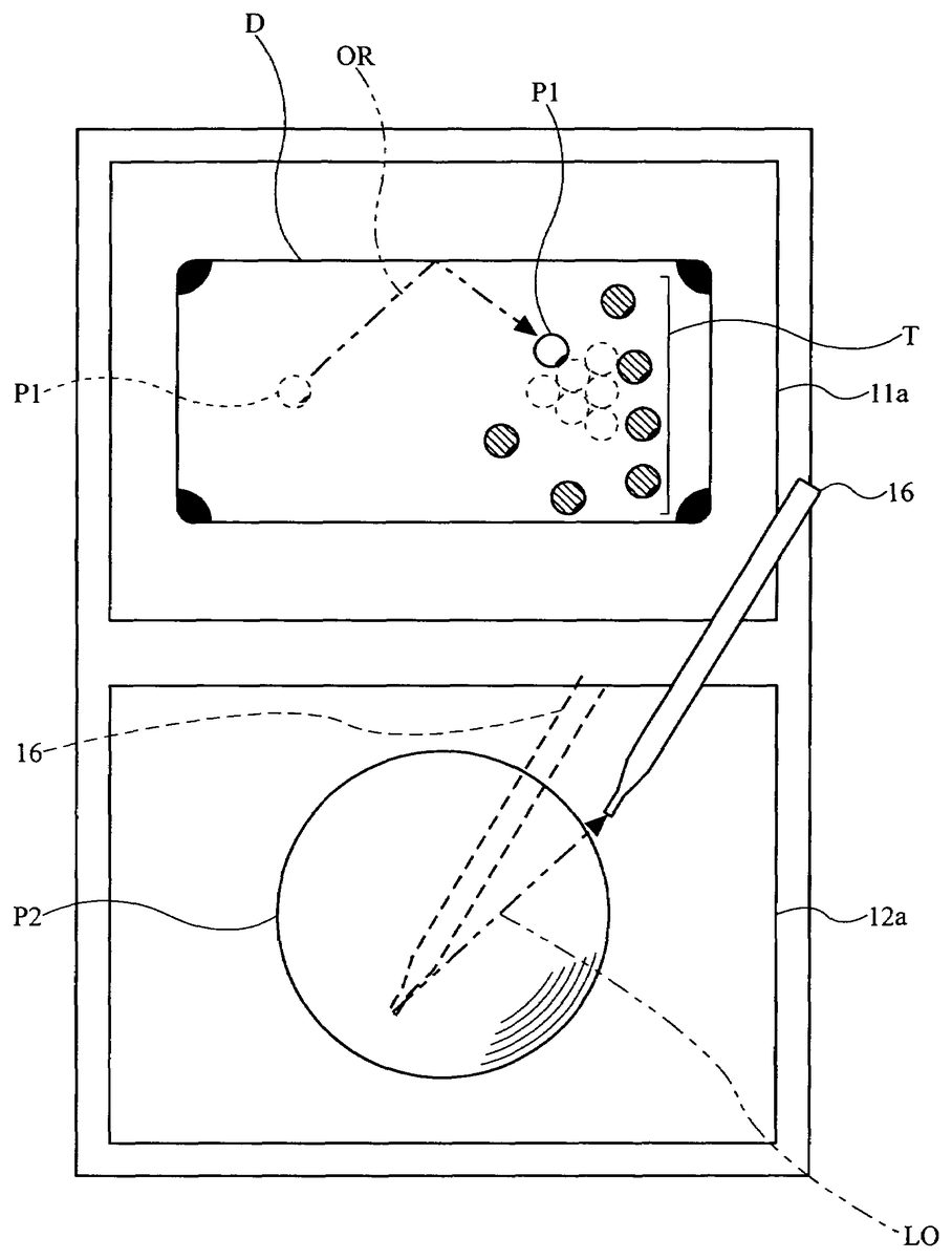
A video game of the video game program of the present embodiment will now be described. In the first embodiment, a player character P1displayed on the first display screen11ais moved according to a change in the input to a character pattern P2on the second display screen12a. The outline of the flow of the video game program will now be described referring toFIG. 3andFIG. 4, before describing the flow in greater detail, in order to facilitate the understanding of the present invention.FIG. 3shows an example of the first game image and the second game image displayed on the first display screen11aand the second display screen12a, respectively, by the video game program.FIG. 4shows an example of how the first game image on the first display screen11achanges in response to a change in the input to the second display screen12a.
As shown inFIG. 3, the first game image is displayed on the first display screen11aof the video game device1, and the second game image representing a graphic pattern associated with the first game image is displayed on the second display screen12a. The first game image shows the game space as viewed from a predetermined point of view. The graphic pattern represented by the second game image is an image of a graphic pattern depending on the type of the game, such as a character or an item appearing in the game space, and the graphic pattern is associated by a program with an image included in the first game image.
Specifically, the video game program renders a dual-screen billiards video game, and displays, as the first game image, a billiard table D including one cue ball P1and six object balls T thereon on the first display screen11a. The cue ball P1is an image of a player character that can be operated by the player, and each object ball T is an image that is moved around on the billiard table D, the movement being induced by a collision with the cue ball P1, etc. An image of the operated cue ball P2, which is an enlarged image of the cue ball P1as viewed from above, is displayed in the second game image on the second display screen12aas the character pattern of the present invention. The cue ball P1and the operated cue ball P2are associated with each other by the video game program so that a change in the input to the operated cue ball P2via the touch panel13is reflected in the change in the appearance (i.e., a movement in the present embodiment) of the cue ball P1in the first game image. Since the second display screen12ais covered by the touch panel13, a change in the input to the operated cue ball P2can be detected by detecting an input to a region of the touch panel13corresponding to the display region of the operated cue ball P2displayed on the second display screen12a.FIG. 4shows how this happens in the first game image and the second game image.
As shown inFIG. 4, the player uses the stylus16to give an input to the touch panel13covering the second display screen12a. In other words, the player specifies an input to the operated cue ball P2displayed on the second display screen12a. The video game device1detects the change in the input to detect a continuous input in a first direction LO, for example. When the continuous input in the first direction LO is detected, the initial direction and the initial velocity, for example, of the cue ball P1on the first display screen11aare calculated based on at least two parameters included in the change in the continuous input. The initial direction and the initial velocity correspond to the change condition data in the present invention. The cue ball P1moves while the movement direction and the movement step are calculated based on the initial direction and the initial velocity, thereby producing the first game image in which the cue ball P1moves along a track line OR on the billiard table D, and the first game image is displayed on the first display screen11a. Thus, the first game image on the first display screen11ais changed based on a change in the input to the touch panel13covering the second display screen12a. While the stylus16is dragged in a straight line in the first direction LO in the illustrated example, it may alternatively be dragged in a curved or S-shaped line. If intermediate coordinate positions between the start point and the end point are used as parameters, the cue ball P1can be moved along an S-shaped track line, for example. In such a case, the cue ball P1is moved while calculating the spin direction and/or the spin speed of the ball.
Next, operations performed by the video game program will be described in detail with reference toFIG. 5andFIG. 6AtoFIG. 6C.FIG. 5is a flow chart showing an operation performed by the video game program,FIG. 6Ais a diagram showing the concept of data stored in the first VRAM27,FIG. 6Bis a diagram showing the concept of data stored in the second VRAM28, andFIG. 6Cis a diagram showing the concept of the coordinate system of the touch panel13.
First, when the power supply (not shown) of the video game device1is turned ON, a boot program (not shown) is executed by the CPU21, whereby the video game program stored in the cartridge17is loaded to the WRAM22. The loaded video game program is executed by the CPU21, thereby performing steps shown inFIG. 5(an abbreviation “S” is used for “step” inFIG. 5).
First, the first GPU23operates in response to an instruction from the CPU21to load various graphics data included in the video game program such as graphics data of a billiard table, and the first game image is rendered in the first VRAM27(step21). Specifically, the billiard table D, the cue ball P1and the object balls T are rendered in the rendering area of the first VRAM27as shown inFIG. 6A. Then, the first game image in the first VRAM27is displayed on the first LCD11. Next, the second GPU24operates in response to an instruction from the CPU21. Graphics data of a character pattern included in the video game program is loaded, and the graphic pattern associated with the first game image is rendered in the second VRAM28as the second game image (step22). Specifically, a character pattern (operated cue ball) P2, being a graphic pattern to be operated, is rendered in the rendering area of the second VRAM28as shown inFIG. 6B. Then, the second game image in the second VRAM28is displayed on the second LCD12. After steps21and22, the player can start playing the billiards video game.
The CPU21starts detecting an input to the touch panel13(step23). As shown inFIG. 6C, the touch panel13has a coordinate system corresponding to that of the second VRAM28for outputting data of a coordinate position corresponding to a position that is input (specified) by the stylus16or a finger of the player. Thus, in step23, the CPU21detects the coordinate position outputted from the touch panel13(including the device driver controlling the touch panel13).
Then, the CPU21determines whether or not there is an input to the character pattern P2(step24). Specifically, the CPU21determines whether or not the coordinate position initially detected on the touch panel13(i.e., the coordinate position to be the start point from which a change in the input starts) is included in a coordinate region P3(seeFIG. 6C) in which the character pattern P2(seeFIG. 6B) is rendered. If the detected coordinate position is included in the coordinate region P3, the CPU21determines that it is an input to the character pattern P2, and the process proceeds to step25. If not, the process repeats step23.
If there is an input to the character pattern P2in step24, the CPU21performs steps25to30as follows to detect a change in the input to the touch panel13. First, the CPU21starts the timer counter for clocking the amount of time for which a continuous input is being made (step25). Then, the CPU21temporarily stores, in the WRAM22, the coordinate position data at the input start point detected in step24(step26). The coordinate position data of the start point stored in step26is the coordinate position at the input start point as used in the example embodiment presented herein.
Then, the CPU21detects input coordinates from the touch panel13at regular intervals (step27), and repeats step27until there is no longer an input from the touch panel13(step28). Thus, in steps27and28, while a touch operation to the touch panel13is being performed continuously, the CPU21keeps detecting the change in the input in response to the touch operation. In the present embodiment, it is determined that the continuous input is finished if the data input from the touch panel13is discontinued even once. In other embodiments, it may be determined that the continuous input is finished only if no data input from the touch panel13is detected over a number of consecutive detections, for example.
When it is determined in step28that there is no longer an input from the touch panel13(i.e., when the player's touch operation to the touch panel13is finished), the CPU21stores the coordinate position data at the input end point in the WRAM22(step29). The coordinate position data of the end point stored in step29is the coordinate position at the input end point as used in the example embodiment presented herein.
Then, the CPU21stops the timer counter when the continuous input is discontinued, and stores, in the WRAM22, continuous input time data representing how long the continuous input has lasted (step30). The continuous input time data stored in step30is the input detection time as used in the example embodiment presented herein.
In steps26and29as described above, at least two parameters (i.e., the coordinate position at the input start point and that at the input end point) are extracted from the change in the input to the touch panel13. In the present embodiment, a total of three parameters are used, including the continuous input time data (input detection time) detected in step30. As will be described later, although the two coordinate positions, one at the start point and another at the end point, are extracted in the present embodiment, the present embodiment is not limited thereto. For example, coordinate position data of some or all of the intermediate points between the start point and the end point may be used in other embodiments. While the amount of time between the start point and the end point is used as the continuous input time data in the present embodiment, time data at an intermediate point between the start point and the end point may be used in other embodiments. Such time data at an intermediate point can be used to change the action of the cue ball P1based on the change in the input during the first half of the period between the start point and the end point, whereby it may be possible to move the cue ball P1more intuitively according to the player's operation. The types and number of parameters to be used can be determined based on the intended action of the player object (the cue ball P1in the present embodiment) on the first display screen11a. More parameters may be needed for a more complicated action, whereas two parameters may suffice for a simple action such as a movement along a straight line.
Then, based on the stored parameters, the CPU21calculates change condition data such as the initial velocity and the movement direction of the cue ball P1in the first game image on the first display screen11a(step31). Specifically, the CPU21calculates the initial velocity and the movement direction of the cue ball P1based on three parameters: the coordinate position data at the input start point (i.e., the start point) obtained in step26; the coordinate position data at the input end point (i.e., the endpoint) obtained in step29; and the continuous input time data between the start point and the end point obtained in step30.
For example, for a start point (x1, y1), an end point (x2, y2) and a continuous input time t1, the CPU21calculates a movement direction (Δx, Δy) by obtaining the differences between the x coordinates and the y coordinates, i.e., Δx=x2−x1and Δy=y2−y1. If the cue ball P1is currently positioned at a coordinate position (X, Y), the cue ball P1is moved from the coordinate position (X, Y) in the movement direction (Δx, Δy) (the first direction LO:FIG. 4). The initial velocity of the cue ball P1is calculated so that the initial velocity is higher for a shorter continuous input time t1. For example, the initial velocity is calculated as follows: initial velocity=predetermined initial velocity/continuous input time t1. The coordinate difference (Δx, Δy) may be taken into consideration in the calculation of the initial velocity so that the initial velocity is higher for a greater difference and vice versa.
The initial velocity and the movement direction can also be calculated by using only two parameters: the start point (x1, y1) or the end point (x2, y2); and the continuous input time t1. For example, the movement direction of the cue ball P1can be calculated as the difference between the start point or the end point and a reference position (x0, y0) (being the center of the character pattern P2), and the initial velocity of the cue ball P1can be calculated based on the continuous input time t1. Moreover, the initial velocity and the movement direction can be calculated using two parameters of the start point (x1, y1) and the end point (x2, y2). For example, the movement direction can be calculated as the difference between the end point and the start point, and the initial velocity can be calculated based on the value of the difference. Thus, the first game image on the first display screen11acan be changed in response to the change in the input to the touch panel13as long as two parameters can be extracted from the change in the input to the touch panel13. In addition to the initial velocity and the movement direction, other conditions for moving the cue ball P1may be calculated, e.g., the acceleration, the deceleration, the movement distance and the movement velocity.
Then, based on the change condition data, such as the initial velocity and the movement direction, being the results of calculation performed based on parameters in step31, the CPU21determines the conditions for moving the cue ball P1. Then, based on the conditions, the CPU21displays, on the first display screen11a, the cue ball P1rolling along the track line OR (seeFIG. 4) while performing calculations with respect to various factors such as the deceleration due to friction against the billiard table, the collision with or reflection off the rails, and the like (step32). The CPU21repeats steps24to32until the game ends (step33).
While the cue ball P1is moved in a straight line based on a change in the input to the touch panel13along a straight line in the present embodiment, the present embodiment is not limited thereto. For example, the player may make a stroke on the touch panel13generally along a straight line while drawing small circles in the generally-straight stroke, in response to which the appearance of the cue ball P1can be changed so that the cue ball P1starts moving in the direction of the straight line with a spin thereon depending on how the circles are drawn and the direction of the circles.
As described above, according to the first embodiment, the cue ball P1moves on the first display screen11aaccording to the change in the input given to the character pattern, i.e., according to the input pattern given through a touch operation on the touch panel13, whereby it is possible to provide a video game with a novel operation. Since the character pattern (the operated cue ball P2) corresponding to the player character (the cue ball P1) displayed on the first display screen11ais displayed on the second display screen12aon a larger scale than the player character, the player can relatively accurately specify an intended position. Since the player operates the character pattern displayed on the second display screen12awhile the player character whose appearance changes is separately displayed on the first display screen11a, it is possible to prevent the player character from being hid from the player by the player's hand performing a touch operation. Since the appearance of the player character on the first display screen11ais changed according to a relatively accurate input position and a relatively accurate change in the input to the character pattern while the appearance of the character pattern displayed on the second display screen12ais not changed, it is possible to visualize a change in the appearance intended by the player on the first display screen11awhile preventing the player from losing track of the graphic pattern to be operated by the player.
Second Embodiment
A video game device including a computer for executing a video game program according to a second embodiment will now be described. While the present embodiment is also directed to a case where the appearance of the player character included in the game image is changed, the appearance of the entire game image may be changed in other embodiments. The video game device of the second embodiment is similar to that of the first embodiment. Therefore, like elements are denoted by like reference numerals, and will not be further described below.
A video game of the video game program of the present embodiment will now be described. Also in the second embodiment, as in the first embodiment, the player character P1is displayed on the first display screen11aand the character pattern P2is displayed on the second display screen12a. The player character P1is moved on the first display screen11aaccording to a change in the input given to the character pattern P2on the second display screen12a. The outline of the flow of the video game program will now be described referring toFIG. 7toFIG. 13, before describing the flow in greater detail.FIG. 7shows an example of a first game image and a second game image displayed on the first display screen11aand the second display screen12a, respectively, by the video game program.FIG. 8shows an example of how the character pattern P2is divided into a plurality of defined regions Z1to Z4.FIG. 9toFIG. 13each show an example of how the first game image on the first display screen11achanges when a change in the input is made on the second display screen12a.
As shown inFIG. 7, the first game image is displayed on the first display screen11aof the video game device1, and the second game image representing a graphic pattern associated with the first game image is displayed on the second display screen12a, as in the first embodiment. The first game image shows the game space as viewed from a predetermined point of view. The graphic pattern represented by the second game image is an image of a graphic pattern depending on the type of the game, such as a character or an item appearing in the game space, and the graphic pattern is associated by a program with an image included in the first game image.
Specifically, the video game program renders a dual-screen billiards video game, and displays, as the first game image, the billiard table D including one cue ball P1and six object balls T thereon on the first display screen11a, as in the first embodiment. The cue ball P1is an image of a player character that can be operated by the player, and each object ball T is an image that is moved around on the billiard table D, the movement being induced by a collision with the cue ball P1, etc. An image of the operated cue ball P2, which is an enlarged image of the cue ball P1as viewed from above, is displayed in the second game image on the second display screen12aas the character pattern of the present invention. The cue ball P1and the operated cue ball P2are associated with each other by the video game program so that a change in the input to the operated cue ball P2via the touch panel13is reflected in the change in the appearance (i.e., a movement in the present embodiment) of the cue ball P1in the first game image. Since the second display screen12ais covered by the touch panel13, a change in the input to the operated cue ball P2can be detected by detecting an input to a region of the touch panel13corresponding to the display region of the operated cue ball P2displayed on the second display screen12a.
As shown inFIG. 7, the player makes a continuous input with the stylus16to the touch panel13covering the second display screen12aso as to specify an input to the operated cue ball P2. The video game device1determines the direction of the continuous input by detecting changes in the continuous input. In the video game program of the second embodiment, a shape Tr is rendered in the second game image in response to changes in the continuous input so as to show the player how the input is being changed. Specifically, where there is a continuous input on the touch panel13starting from a start point S in the display region of the operated cue ball P2, the shape Tr is rendered according to the positional relationship between the start point S and a current point N. The shape Tr is an isosceles triangle in which the point N is the apex, the base has a predetermined length, and the start point S is located at the midpoint along the base.
When the continuous input is detected and the continuous input is finished, the movement step (movement direction), the velocity, etc., of the cue ball P1on the first display screen11aare calculated based on at least two parameters (e.g., the start point and the end point of the continuous input) included in the change in the continuous input. In the present embodiment, the shot mode is also determined based on the parameters.
Specifically, the shot mode is determined based on the relationship between the positions of the start point S and the end point E included in the change in the continuous input and the defined regions obtained by dividing the display region of the operated cue ball P2. The display region of the operated cue ball P2is divided into, for example, four defined regions Z1to Z4, as shown inFIG. 8. The positions of the defined regions Z1to Z4vary depending on the direction from the start point S to the endpoint E (hereinafter referred to as the “input direction”)FIG. 8shows the defined regions Z1to Z4where the input direction is an upward direction on the drawing sheet.
Referring toFIG. 8, a straight line M is defined to be perpendicular to the input direction and passing through the center of the operated cue ball P2. A point F1is defined as a point along the circumference of the operated cue ball P2that is 22.5° off the input direction rightward, and a point F2is defined as a point along the circumference of the operated cue ball P2that is 22.5° off the input direction leftward (thus the points F1and F2together make an angle of 45° with respect to the center of the operated cue ball P2). Similarly, a point R1is defined as a point along the circumference of the operated cue ball P2that is 22.5° off a direction opposite to the input direction rightward, and a point R2is defined as a point along the circumference of the operated cue ball P2that is 22.5° off a direction opposite to the input direction leftward (thus the points R1and R2together make an angle of 45° with respect to the center of the operated cue ball P2). In other words, the angle between the point F1and the point R1is 135°, and the angle between the point F2and the point R2is also 135°. A straight line F1-R1is defined between the point F1and the point R1, and a straight line F2-R2is defined between the point F2and the point R2. Then, the straight line F1-R1and the straight line F2-R2are both parallel to the input direction, and the display region of the operated cue ball P2is divided in three by the-straight line F1-R1and the straight line F2-R2. A region on the right-hand side of the straight line F1-R1(i.e., the most rightward region of the three divisions) is the defined region Z3. A region on the left-hand side of the straight line F2-R2(i.e., the most leftward region of the three divisions) is the defined region Z4. A region between the straight line F1-R1and the straight line F2-R2(i.e., the center region of the three divisions) corresponds to the defined regions Z1and Z2. The region between the straight line F1-R1and the straight line F2-R2is further divided into an upper region and a lower region by the straight line M. The upper region is the defined region Z1, and the lower region is the defined region Z2. As described above, the defined regions Z1to Z4are determined based on the input direction, and thus the orientation of the defined regions Z1to Z4vary depending on the input direction. Specifically, the defined regions Z1to Z4are rotated about the center of the operated cue ball P2as the input direction changes.
The defined regions Z1to Z4may or may not be displayed in the second game image. As will be described later, since the operated cue ball P2is divided into the defined regions Z1to Z4in such a manner that the change in the appearance of the cue ball P1(the shot mode) can be predicted based on the direction in which the cue ball P1is moved, the player can intuitively make the prediction even if the defined regions Z1to Z4are not displayed in the game image. In the above description, the operated cue ball P2displayed in the second game image is divided into the defined regions Z1to Z4for the sake of simplicity. In practice, however, the coordinate region P3in which the operated cue ball P2is rendered (seeFIG. 6C) can be divided into the defined regions Z1to Z4.
There are various shot modes different from one another in how the cue ball moves, and one of the shot modes is selected depending on the point at which the cue strikes the cue ball. Specifically, there can be various shot modes depending on the position at which the cue ball P1is struck, including “center ball” where the cue strikes the center of the cue ball P1, “draw” where a lower portion of the cue ball P1is struck, “follow” where an upper portion of the cue ball P1is struck, “left curve” where a right portion of the cue ball P1is struck, and “right curve” where a left portion of the cue ball P1is struck. If the start point S included in the change in the continuous input is located in the defined region Z3, the shot mode is set to “left curve”. If the start point S included in the change in the continuous input is located in the defined region Z4, the shot mode is set to “right curve”. If the start point S included in the change in the continuous input is located in the defined region Z1, the shot mode is set to “follow”. If the start point S and the end point E included in the change in the continuous input are both located in the defined region Z2, the shot mode is set to “draw”. If the start point S included in the change in the continuous input is located in the defined region Z2and if the end point E is located in the defined region Z1or outside the display region of the operated cue ball P2, the shot mode is set to “center ball”.
The movement step (the movement direction), the velocity and the shot mode correspond to the change condition data as used in the present embodiment. The cue ball P1is moved while the movement direction, the movement step, the spin direction, the spin speed, etc., of the cue ball P1are calculated based on the change condition data, thereby producing the first game image in which the cue ball P1moves on the billiard table D, and the first game image is displayed on the first display screen11a.
FIG. 9toFIG. 13each show an example of the first game image in which the cue ball P1moves on the billiard table D according to a particular shot mode. In all of the examples shown inFIG. 9toFIG. 13, the input direction (indicated by an arrow extending from “S” to “E”) is from left to right on the drawing sheet.
InFIG. 9, the start point S of the continuous input is located in the defined region Z2of the operated cue ball P2, and the end point E is located in the defined region Z1. When such a continuous input is detected, the movement step (the movement direction), the velocity and the shot mode for the cue ball P1on the first display screen11aare calculated based on at least two parameters indicating the positions of the start point S and the end point E included in the change in the continuous input. In the illustrated example, the shot mode is set to “center ball”. The cue ball P1is moved while the movement step, the velocity, etc., of the cue ball P1are calculated based on the shot mode “center ball”, thereby producing the first game image in which the cue ball P1moves on the billiard table D along the track line g, and the first game image is displayed on the first display screen11a. As shown inFIG. 9, in the shot mode “center ball”, the track line g is a straight line extending in the input direction and no spin is set for the cue ball P1until the cue ball contacts another object.
InFIG. 10, the start point S of the continuous input is located in the defined region Z3of the operated cue ball P2, and the end point E is located outside the display region of the operated cue ball P2. Then, the shot mode is set to “left curve”, and the movement step and the velocity for the cue ball P1are calculated based on at least two parameters indicating the positions of the start point S and the end point E. The cue ball P1is moved while the movement step, the velocity, the spin direction, the spin speed, etc., of the cue ball P1are calculated based on the shot mode “left curve”, thereby producing the first game image in which the cue ball P1moves on the billiard table D along the track line g, and the first game image is displayed on the first display screen11a. As shown inFIG. 10, in the shot mode “left curve”, a leftward spin is set for the cue ball P1, and the track line g is a line gradually curving to the left off the input direction until the cue ball contacts another object.
InFIG. 11, the start point S of the continuous input is located in the defined region Z4of the operated cue ball P2, and the end point E is located outside the display region of the operated cue ball P2. Then, the shot mode is set to “right curve”, and the movement step and the velocity for the cue ball P1are calculated based on at least two parameters indicating the positions of the start point S and the end point E. The cue ball P1is moved while the movement step, the velocity, the spin direction, the spin speed, etc., of the cue ball P1are calculated based on the shot mode “right curve”, thereby producing the first game image in which the cue ball P1moves on the billiard table D along the track line g, and the first game image is displayed on the first display screen11a. As shown inFIG. 11, in the shot mode “right curve”, a rightward spin is set for the cue ball P1, and the track line g is a line gradually curving to the right off the input direction until the cue ball contacts another object.
InFIG. 12, the start point S and the end point E of the continuous input are both located in the defined region Z2of the operated cue ball P2. Then, the shot mode is set to “draw”, and the movement step and the velocity for the cue ball P1are calculated based on at least two parameters indicating the positions of the start point S and the end point E. The cue ball P1is moved while the movement step, the velocity, the spin direction, the spin speed, etc., of the cue ball P1are calculated based on the shot mode “draw”, thereby producing the first game image in which the cue ball P1moves on the billiard table D along the track line g, and the first game image is displayed on the first display screen11a. As shown inFIG. 12, in the shot mode “draw”, a backward spin is set for the cue ball P1, and the track line g is a straight line extending in the input direction until the cue ball contacts another object. After the cue ball contacts an object ball T, the cue ball is pulled back away from the object ball T.
InFIG. 13, the start point S of the continuous input is located in the defined region Z1of the operated cue ball P2, and the end point E is located outside the display region of the operated cue ball P2. Then, the shot mode is set to “follow”, and the movement step and the velocity for the cue ball P1are calculated based on at least two parameters indicating the positions of the start point S and the end point E. The cue ball P1is moved while the movement step, the velocity, the spin direction, the spin speed, etc., of the cue ball P1are calculated based on the shot mode “follow”, thereby producing the first game image in which the cue ball P1moves on the billiard table D along the track line g, and the first game image is displayed on the first display screen11a. As shown inFIG. 13, in the shot mode “follow”, a forward spin is set for the cue ball P1, and the track line g is a straight line extending in the input direction until the cue ball contacts another object. After the cue ball contacts an object ball T, the split angle from the object ball T is smaller than that in other shot modes (e.g., the cue ball follows the object ball T that it has just hit). Thus, the first game image on the first display screen11ais changed based on a change in the input to the touch panel13covering the second display screen12a.
Next, operations performed by the video game program will be described in detail with reference toFIG. 14toFIG. 21.FIG. 14is a flow chart showing an operation performed by the video game program.FIG. 15shows in detail a subroutine of a touch panel input operation in step57ofFIG. 14.FIG. 16shows in detail a subroutine of a change condition data calculation operation in step61ofFIG. 14.FIG. 17shows in detail a subroutine of a shot mode detection operation in step84ofFIG. 16.FIG. 18shows in detail a subroutine of a cue ball display position updating operation in step62ofFIG. 14.FIG. 19shows in detail a subroutine of a cue ball contact operation in step123ofFIG. 18.FIG. 20shows in detail a subroutine of a gStepX and gStepY updating operation in step134ofFIG. 18.FIG. 21shows how to produce the isosceles triangle Tr displayed in step74ofFIG. 15. The first VRAM27, the second VRAM28and the touch panel13as used in the operations performed by the video game program are similar in concept to those illustrated inFIG. 6AtoFIG. 6Cin the first embodiment.
The operation at power-on of the video game device1is similar to that of the first embodiment. Steps51to56ofFIG. 14are similar to steps21to26ofFIG. 5in the first embodiment, and will not be further described below.
In step57, the CPU21performs the touch panel input operation at regular intervals. The CPU21repeats the operation of step57until there is no longer an input from the touch panel13(step58). Thus, in steps57and58, while a touch operation to the touch panel13is being performed continuously, the CPU21continues to perform the input processing operation in response to the touch operation. In the present embodiment, it is determined that the continuous input is finished if the data input from the touch panel13is discontinued even once. In other embodiments, it may be determined that the continuous input is finished only if no data input from the touch panel13is detected over a number of consecutive detections, for example. Referring toFIG. 15, the touch panel input operation in step57will now be described in detail.
Referring toFIG. 15, the CPU21determines whether or not it is the first input from the touch panel13(step71). If it is the first input, the CPU21displays, in the second game image, a straight line having a length L on the left and right of the coordinate position of the start point (step72), and the process exits the subroutine. The coordinate position data at the input start point stored in step56is used as the coordinate position of the start point. As a result of the operation in step72, a horizontal straight line having a length of 2L is rendered on the second display screen12a, with the start point touched by the player being located at the midpoint along the straight line.
If it is determined in step71that the input is a second or subsequent input, the CPU21temporarily stores, in the WRAM22, the coordinate position input from the touch panel13as the coordinate position data of the current point N (step73). Then, the CPU21displays the isosceles triangle Tr with the point N being the apex (seeFIG. 7) in the second game image (step74), and the process exits the subroutine. The base of the isosceles triangle Tr has a length of 2L, and the isosceles triangle Tr is rendered so that the start point stored in step56is at the midpoint along the base. Referring toFIG. 21, how the CPU21produces the isosceles triangle Tr will now be described.
Referring toFIG. 21, the start point is denoted as a point S. On the xy plane, the point N is located at the coordinate position N(Nx, Ny), and the point S is located at the coordinate position S(Sx,Sy) The point N(Nx, Ny) is rotated about the point S(Sx, Sy) by 90° and by −90° to obtain points N1and N2, respectively. The x and y coordinates of the points N1and N2are calculated as follows.
N1x=cos(90°)×(Nx−Sx)−sin(90°)×(Ny−Sy)
N1y=sin(90°)×(Nx−Sx)+cos(90°)×(Ny−Sy)
N2x=cos(−90°)×(Nx−Sx)−sin(−90°)×(Ny−Sy)
N2y=sin(−90°)×(Nx−Sx)+cos(−90°)×(Ny−Sy)
The length Q of the straight line between the point S and the point N is as follows.
Q=√{square root over ((Nx−Sx)2+(Ny−Sy)2)}{square root over ((Nx−Sx)2+(Ny−Sy)2)}
Points S1and S2at the opposite ends of the base of the isosceles triangle Tr are located along the straight line N1-N2. Therefore, the x and y coordinates of the points S1and S2are calculated as follows.
S1x=(L/Q)×N1x+Sx
S1y=(L/Q)×N1y+Sy
S2x=(L/Q)×N2x+Sx
S2y=(L/Q)×N2y+Sy
Connecting these points N, S1and S2together with straight lines yields the isosceles triangle Tr in which the length of the base is 2L and the apex is the point N, with the start point S being at the midpoint along the base.
In step74, a shape other than an isosceles triangle may be rendered. Any other suitable shape may be used as long as it indicates both the direction and the distance between the start point S and the point N, e.g., a line connecting between the start point S and the point N or an arrow extending from the start point S to the point N.
Referring back toFIG. 14, if there is no longer an input from the touch panel13(i.e., if the touch operation to the touch panel13by the player is finished) in step58, the process proceeds to step59. Steps59and60inFIG. 14are similar to steps29and30ofFIG. 5in the first embodiment, and will not be further described below. Through steps56and59, at least two parameters (the coordinate positions at the input start point and the input end point) are extracted from the change in the input to the touch panel13. In the present embodiment, a total of three parameters are used, including the continuous input time data (input detection time) detected in step60. Also in the present embodiment, the types and number of parameters to be used can be determined based on the intended action of the player object (the cue ball P1in the present embodiment) on the first display screen11a.
Then, based on the stored parameters, the CPU21calculates the change condition data such as the movement step (movement direction), the velocity and the shot mode of the cue ball P1in the first game image on the first display screen11a(step61). Specifically, the CPU21calculates the movement step (movement direction) and the velocity of the cue ball P1based on three parameters: the coordinate position data at the input start point (i.e., the start point) obtained in step56; the coordinate position data at the input end point (i.e., the end point) obtained in step59; and the continuous input time data between the start point and the end point obtained in step60. The change condition data calculation operation will now be described in detail with reference toFIG. 16.
Referring toFIG. 16, the CPU21calculates the difference between the end point E (x2, y2) and the start point S (x1, y1), i.e., Δx=x2−x1and Δy=y2−y1(step81). The CPU21has obtained the continuous input time t1in step60. Then, the CPU21determines whether or not the continuous input time t1is zero or the differences Δx and Δy are both zero (step82). If the continuous input time t1is zero or Δx and Δy are both zero, the CPU21turns OFF the movement flag (step83), and the process exits the subroutine. If t1is greater than zero and if at least one of Δx and Δy is not zero, the process proceeds to step84.
In step84, the CPU21detects the shot mode using the coordinate position data of the start point S and the end point E. The shot mode detection operation will now be described in detail with reference toFIG. 17.
Referring toFIG. 17, the CPU21calculates a straight line SE passing through the end point E and the start point S (step101). The straight line SE passing through the start point S (x1, y1) and the end point E (x2, y2) can be obtained as follows.
y=y2-y1x2-x1(x-x1)+y1
Then, the CPU21calculates two intersection points Q1and Q2between the straight line SE and a circle coincident with the circumference of the operated cue ball P2(step102). The circle coincident with the circumference of the operated cue ball P2is expressed as follows:
x2+y2=r
where r is the radius of the circle. The x coordinates of the intersection points between the straight line SE and the circle can be obtained as follows.
x=-2AB±4A2B2-4(A2+1)(B2-r2)2(A2+1)
In this expression, A=(y2−y1)/(x2−x1) and B=y1−A*x1. The y coordinates of the two intersection points Q1and Q2can be obtained by substituting the obtained x coordinates into the expression of the straight line SE. The intersection point Q2is one of the two intersection points that is closer to the end point E (x2, y2).
Then, the CPU21calculates the angles of straight lines connecting between the center of the circle and the two intersection points Q1and Q2(step103). The angles can be obtained by substituting the x and y coordinates of the two intersection points obtained in step102into atan (y/x). Where x=0, the angle is set to 90° or 270°. Where x1=x2, the angles are obtained by atan (y2/x2) and atan (y1/x1) in step103, and where x1=0 or x2=0, the angle is set to 90° or 270°.
Then, the CPU21calculates the difference between the angles obtained in step103(step104). Specifically, the angle corresponding to the intersection point Q1is subtracted from the angle corresponding to the intersection point Q2. If the subtraction result is a positive value, the subtraction result is used as it is as the angular difference. If the subtraction result is a negative value, the angular difference is obtained by adding 360° to the subtraction result.
If the absolute value of the angular difference is less than or equal to 135° (i.e., Yes in step105), the CPU21sets the shot mode to “left curve” and turns ON the left curve flag (step106), and the process exits the subroutine. If the absolute value of the angular difference is equal to or greater than 225° (i.e., Yes in step107), the CPU21sets the shot mode to “right curve” and turns ON the right curve flag (step108), and the CPU21exits subroutine. In other words, in step105, the CPU21determines whether or not the start point S of the continuous input is located in the defined region Z3of the operated cue ball P2(seeFIG. 10). In step107, the CPU21determines whether or not the start point S of the continuous input is located in the defined region Z4of the operated cue ball P2(seeFIG. 11).
If the absolute value of the angular difference is greater than 135° and less than 225° (i.e., No in both steps105and107), the CPU21calculates a perpendicular line to the straight line SE that passes through the center of the circle (step109). Then, the CPU21calculates the positions of the start point S and the end point E with respect to the perpendicular line obtained in step109(step110). If the start point S and the end point E are both located closer to the defined region Z1with respect to the perpendicular line (seeFIG. 8) (i.e., Yes in step111), the CPU21sets the shot mode to “follow” and turns ON the follow flag (step112), and the process exits the subroutine. If the start point S and the end point E are both located closer to the defined region Z2with respect to the perpendicular line (i.e. Yes in step113), the CPU21sets the shot mode to “draw” and turns ON the draw flag (step114), and the process exits the subroutine. If the start point S and the end point E are located in different regions with respect to the perpendicular line (specifically, if the start point S is located in the defined region Z2and the end point E is located in the defined region Z1) (i.e., No in both steps111and113), the CPU21sets the shot mode to “center ball” and turns ON the center ball flag (step115), and the process exits the subroutine. In other words, if the decision result is Yes in step111, the CPU21determines that the start point S of the continuous input is located in the defined region Z1of the operated cue ball P2(seeFIG. 13). If the decision result is Yes in step113, the CPU21determines that the start point S and the end point E of the continuous input are both located in the defined region Z2of the operated cue ball P2(seeFIG. 12). If the decision result is No in step113, the CPU21determines that the start point S of the continuous input is located in the defined region Z2of the operated cue ball P2while the end point E is located in the defined region Z1(seeFIG. 9).
The perpendicular line to the straight line SE passing through the center of the circle, which is calculated in step109, is obtained as follows.
y=−{(x2−x1)/(y2−y1)}x
The CPU21can perform the decision operations in steps111and113based on the sign of two values C1and C2, which are calculated as follows.
C1=y1+{(x2−x1)/(y2−y1)}x1
C2=y2+{(x2−x1)/(y2−y1)}x2
In step111, if the values C1and C2are both positive, the CPU21determines that the start point S and the end point E are both closer to the defined region Z1with respect to the perpendicular line. In step113, if the values C1and C2are both negative, the CPU21determines that the start point S and the end point E are both located closer to the defined region Z2with respect to the perpendicular line.
Referring back toFIG. 16, after detecting the shot mode in step84, the CPU21compares the absolute values of the differences Δx and Δy calculated in step81with each other to determine if |Δx|>|Δy| holds true (step85). If |Δx|>|Δy| holds true, the CPU21calculates the movement steps (movement directions) gStepX and gStepY per unit time with respect to the x axis direction (step86), and the process proceeds to step88. Specifically, in step86, if the difference Δx is a positive value, the movement step gStepX in the x axis direction is set to 1.0. If the difference Δx is a negative value, the movement step gStepX is set to −1.0. The movement step in the y axis direction is calculated as gStepY=Δy/|Δx|.
If |Δx|≦51Δy| holds true, the CPU21calculates the movement steps (movement directions) gStepX and gStepY per unit time with respect to the y axis direction (step87), and the process proceeds to step88. Specifically, in step87, if the difference Δy is a positive value, the movement step gStepY in the y axis direction is set to 1.0. If the difference Δy is a negative value, the movement step gStepY is set to −1.0. The movement step in the x axis direction is calculated as gStepX=Δx/|Δy|.
Instep88, the CPU21turns ON the movement flag. Then, the CPU21calculates the velocity of the cue ball P1based on the distance between the start point S and the end point E and the continuous input time t1(step89). The distance Lse between the start point S and the end point E is obtained as follows.
Lse=√{square root over (Δx2+Δy2)}
While the velocity of the cue ball P1is calculated so that it is higher as the continuous input time t1is shorter, the influence of the continuous input time t1is reduced herein. For example, a value11abeing a square root of a value obtained by dividing the continuous input time t1by a constant (e.g.,16) is used. Then, the velocity gSpeed of the cue ball P1is obtained as follows.
gSpeed=Lse/t1a+Sp1
In this expression, Sp1is the minimum velocity constant (e.g.,16). If the calculated velocity gSpeed exceeds a predetermined maximum velocity, the velocity gSpeed is set to the maximum velocity. Therefore, the initial value of the velocity gSpeed of the cue ball is set to be between the minimum velocity and the maximum velocity according to the touch operation by the player.
The movement steps gStepX and gStepY calculated in step86or step87and the velocity gSpeed calculated in step89may be adjusted according to the intended action of the cue ball P1on the first display screen11a. For example, the action of the cue ball P1to be rendered on the first display screen11acan be adjusted by multiplying the velocity gSpeed by a constant (e.g.,88) or dividing the movement steps gStepX and gStepY by a constant (e.g.,16).
Then, the CPU21determines whether or not one of the left curve flag and the right curve flag (hereinafter referred to collectively as the “curve flag”) is ON (step90). If the curve flag is OFF, the process exits the subroutine. If the curve flag is ON, the CPU21sets a curve coefficient k (step91), and the process exits the subroutine. The curve coefficient k represents an angle by which the cue ball P1is curved, and the absolute value thereof is set to be larger as the straight line (straight line SE) between the start point S and the end point E is farther away from the center of the operated cue ball P2. For example, the curve coefficient k is set so that the angle by which the cue ball P2is curved in the operation of moving the display position of the cue ball P1to be described later is about 2° to about 7°. Specifically, the curve coefficient k is determined by using the angle calculated in step103. For example, if the shot mode is “left curve”, the curve coefficient k is set to (α−67)/24−4.5, where α is the angle calculated in step103. If the shot mode is “right curve”, the curve coefficient k is set to (α−292)/24+4.5. With these expressions, the curve coefficient k is set to a negative value for “left curve” and to a positive value for “right curve”. These expressions for calculating the curve coefficient k may also be adjusted according to the intended action of the cue ball P1on the first display screen11a.
Referring back toFIG. 14, based on the change condition data such as the movement step and the velocity calculated in the change condition data calculation operation of step61, the CPU21updates the display position of the cue ball P1, thereby rendering the rolling of the cue ball P1on the first display screen11a(step62). The cue ball display position updating operation will now be described in detail with reference toFIG. 18.
InFIG. 18, the CPU21determines whether or not the movement flag is ON (step120). If the movement flag is ON, the process proceeds to step121, and if the movement flag is OFF, the process exits the subroutine.
In step121, the CPU21sets a loop counter LC for counting the number of loop iterations for determining the movement step per unit time, the movement direction, etc., of the cue ball P1to a value according to the current velocity gSpeed. For example, the loop counter LC is set to a value calculated as gSpeed/128+1 (dropping fractions below decimal point), whereby the loop counter LC is set to 1 or more according to the velocity gSpeed. The value of the loop counter LC may also be adjusted according to the intended action of the cue ball P1on the first display screen11a.
Then, the CPU21adds the current movement steps gStepX and gStepY to the current x and y coordinate values of the display position of the cue ball P1, respectively (step122). Then, based on the display position (the x and y coordinates) of the cue ball P1to which gStepX and gStepY have been added in step122, the CPU21performs an operation of handling a contact of the cue ball P1with another object (step123). The cue ball contact operation will now be described in detail with reference toFIG. 19.
Referring toFIG. 19, the CPU21determines whether or not the cue ball P1contacts a rail of the billiard table D based on the display position (the x and y coordinates) of the cue ball P1to which gStepX and gStepY have been added in step122(step141). Then, if it is determined that the cue ball P1contacts a rail of the billiard table D, the CPU21determines whether or not the contacted rail is the upper or lower rail in the first display screen11a(step142). If the contacted rail is not the upper or lower rail of the billiard table D (i.e., if the contacted rail is the left or right rail), the CPU21inverts the sign of the current movement step gStepX, and the process proceeds to step145. If the contacted rail is the upper or lower rail of the billiard table D, the CPU21inverts the sign of the current movement step gStepY, and the process proceeds to step145.
In step145, the CPU21decreases the velocity gSpeed of the cue ball P1based on a predetermined deceleration rate set for a contact with a rail. For example, the velocity gSpeed is decreased by multiplying the current velocity gSpeed by ⅞. Then, the process proceeds to step149.
If it is determined in step141that the cue ball P1does not contact a rail of the billiard table D, the CPU21determines whether or not the cue ball P1falls into a pocket of the billiard table D (step146). If the cue ball P1falls into a pocket, the CPU21sets the velocity gSpeed to zero and performs a pocket-in process (step147), after which the CPU21turns OFF the movement flag (step148), and the process exits the subroutine. If the cue ball P1does not fall into a pocket, the process proceeds to step149.
In step149, based on the display position (the x and y coordinates) of the cue ball P1to which gStepX and gStepY have been added in step122, it is determined whether or not the cue ball P1contacts another object ball T. If the cue ball P1contacts another object ball T, the process proceeds to step150. If the cue ball P1does not contact another object ball T, the process exits the subroutine.
In step150, the CPU21detects the conditions under which the cue ball P1contacts the object ball T. The contact conditions include the movement direction and the movement velocity (movement vector) of each of the cue ball P1and the contacted object ball T, as well as the angle and the point at which the cue ball P1contacts the object ball T. Then, based on the contact conditions detected in step150, the CPU21updates the movement steps gStepX and gStepY of the cue ball P1(step151). For example, the movement steps gStepX and gStepY are updated by using the result of adding together the movement vector of the cue ball P1and that of the object ball T. Moreover, depending on the positions of the cue ball P1and the object ball T, the signs of the movement steps gStepX and gStepY are inverted. The movement steps gStepX and gStepY are updated based on the contact conditions as described above. This process will not be further described herein.
Then, based on the contact conditions detected in step150, the CPU21updates the velocity gSpeed of the cue ball P1(step152). For example, the velocity gSpeed is updated to zero if the cue ball P1collides head to head with the object ball T with the center of the object ball T being aligned with the movement direction of the cue ball P1. Otherwise, the deceleration on the velocity gSpeed is decreased as the center of the object ball T is more shifted from the movement direction of the cue ball P1. In the present embodiment, if the cue ball P1contacts a standing object ball T, the velocity gSpeed of the cue ball P1is decreased by at least 50%. If the movement velocity of the contacted object ball T is higher than the movement velocity of the cue ball P1, the velocity gSpeed of the cue ball P1may be increased. The velocity gSpeed is updated based on the contact conditions as described above. This process will not be further described herein.
Then, the CPU21calculates the movement step and the velocity for the object ball T contacted by the cue ball P1(step153). The movement step and the velocity of the object ball T are set and updated based on the contact conditions as described above, as with the cue ball P1. This process will not be further described herein.
Then, the CPU21determines whether or not the shot mode of the cue ball P1is “follow” or “draw” (step154). Specifically, the CPU21makes the determination based on the follow flag, which is turned ON in step112, and the draw flag, which is turned ON in step114. If the shot mode of the cue ball P1is “follow” or “draw”, the CPU21sets a curve coefficient k according to the shot mode (step155), and the process exits the subroutine. If the shot mode of the cue ball P1is neither “follow” nor “draw”, the process directly exits the subroutine. If the shot mode is “follow”, the curve coefficient k is set in step155so that the split angle from the object ball T is smaller than that in other shot modes (e.g., the cue ball P1follows the object ball T that it has just hit) in the operation of moving the display position of the cue ball P1to be described later. If the shot mode is “draw”, the curve coefficient k is set so that the split angle from the object ball T is larger than that in other shot modes (e.g., the cue ball is pulled back away from the object ball T that it has just hit) in the operation of moving the display position of the cue ball P1. In the present embodiment, the curve coefficient k is set to +3° if the shot mode is “follow”, and to −3° if the shot mode is “draw”. The values of the curve coefficient k are not limited to the fixed values mentioned above. The curve coefficient k may be adjusted according to the intended action of the cue ball P1on the first display screen11a, and the value thereof may be varied depending on the contact conditions, for example.
Referring back toFIG. 18, after the cue ball contact operation in step123, the CPU21determines whether or not the cue ball P1contacts another object (step124) based on the display position (the x and y coordinates) of the cue ball P1to which gStepX and gStepY have been added in step122. The contact between the cue ball P1and another object can be determined based on the operation result from step123, and if the cue ball P1does not contact another object (i.e., No in all of steps141,146and149), the CPU21decrements the value of the loop counter LC by1(step125). Then, the CPU21determines whether or not the value of the loop counter LC is zero (step126). If the value of the loop counter LC is not zero, the CPU21returns to step122to repeat the operation.
If the value of the loop counter LC is zero, the CPU21specifies the current x and y coordinates of the display position of the cue ball P1as the display position of the cue ball P1in the first game image and displays the cue ball P1on the first display screen11a(step127), and the process proceeds to step128. Step127is an operation that is repeated by the CPU21at regular intervals, and the display position of the cue ball P1in the first game image is updated at regular intervals. The display position of the cue ball P1is updated as movement steps gStepX and gStepY are added to the current x and y coordinates of the cue ball P1in step122and the addition process is repeated a number of times equal to the initial value of the loop counter LC. Thus, the cue ball P1is displayed in the first game image while being moved to a new display position at regular intervals, the new display position being calculated by adding the movement steps gStepX and gStepY to the x and y coordinates of the cue ball P1a number of times equal to the initial value of the loop counter LC. Since the initial value of the loop counter LC is determined according to the velocity gSpeed, the cue ball P1is displayed in the first game image while being moved according to the movement steps gStepX and gStepY and the velocity gSpeed at regular intervals.
If it is determined in step124that the cue ball P1contacts another object (i.e., Yes in step141,146or149), the CPU21specifies the current x and y coordinates of the display position of the cue ball P1as the display position of the cue ball P1in the first game image and displays the cue ball P1on the first display screen11a(step136), and returns to step120to repeat the operation. The operation of step136is similar to that of step127, and will not be further described below.
After displaying the cue ball P1in the first game image in step127, the CPU21determines whether or not the velocity gSpeed is high (step128) and whether or not the velocity gSpeed is medium (step129). Steps128and129are an operation in which the CPU21determines whether the current velocity gSpeed of the cue ball P1is high, medium or low. For example, a high speed is defined as gSpeed≧512, a medium speed as 512>gSpeed≧256, and a low speed as 256>gSpeed.
If it is determined that the velocity gSpeed is high (i.e., Yes in step128), the CPU21decreases the current velocity gSpeed based on a coefficient of friction to set a new velocity gSpeed (step130), and the process proceeds to step133. Specifically, in step130, a value obtained by dividing the velocity gSpeed by a predetermined friction constant (e.g.,28) is subtracted from the velocity gSpeed. If it is determined that the velocity gSpeed is medium (i.e., Yes in step129), the CPU21subtracts a constant b (e.g., b=16) from the current velocity gSpeed to set a new velocity gSpeed (step131), and the process proceeds to step133. If it is determined that the velocity gSpeed is low i.e., (No in steps128and129), the CPU21subtracts a constant c(b>c; e.g., c=7) from the current velocity gSpeed to obtain a new velocity gSpeed (step132), and the process proceeds to step133. The classification of the velocity gSpeed and the deceleration value may be adjusted according to the intended action of the cue ball P1on the first display screen11a. For example, the number of classes of the velocity gSpeed may be increased while setting a deceleration value for each of the velocity classes.
In step133, the CPU21determines whether or not gSpeed≦0 holds true. If gSpeed≦0 holds true, the CPU21turns OFF the movement flag (step135), and the process exits the subroutine. If gSpeed>0, the CPU21updates the movement steps gStepX and gStepY (step134), and returns to step120to repeat the operation. Thus, the cue ball display position updating operation is repeated until the velocity gSpeed is less than or equal to zero. The operation of updating the movement steps gStepX and gStepY will now be described in detail with reference toFIG. 20.
Referring toFIG. 20, the CPU21determines whether or not the center ball flag, as an indicator of the shot mode of the cue ball P1, is ON (step161), whether or not the follow flag or the draw flag is ON (step162), and whether or not the curve flag is ON (step163). If the center ball flag is ON (i.e., Yes in step161), the process proceeds to step166. If the follow flag or the draw flag is ON (i.e., Yes in step162), the CPU21determines whether or not a curve coefficient k according to the flag being ON has been set (step164). If it is determined that a curve coefficient k according to the flag being ON has not been set (i.e., No instep164), the process proceeds to step166. Otherwise (i.e., Yes in step164), the process proceeds to step165. If it is determined that the curve flag is ON (i.e., Yes in step163), the process proceeds to step165. If it is determined that none of the flags is ON (i.e., No in all of steps161to163), the process proceeds to step166.
In step165, the CPU21decreases the absolute value of the curve coefficient k by a predetermined amount, and the process proceeds to step166. For example, where a curve coefficient k according to the curve flag being ON has been set, the CPU21decreases the absolute value of the curve coefficient k by 0.1. If a curve coefficient k according to the follow flag or the draw flag being ON has been set, the CPU21decreases the absolute value of the curve coefficient k by 0.2. The amount by which the curve coefficient k is decreased may be adjusted according to the intended action of the cue ball P1on the first display screen11a.
In step166, the CPU21updates the movement steps gStepX and gStepY based on the curve coefficient k, and the process exits the subroutine. If the curve coefficient k has not been set, the curve coefficient k is set to zero. Specifically, the CPU21updates the movement steps gStepX and gStepY based on the following expressions.
gStepX=cosk*gStepX−sink*gStepY
gStepY=sink*gStepX+cosk*gStepY
In these expressions, gStepX and gStepY on the left side are the updated movement steps gStepX and gStepY. Moreover, gStepX and gStepY on the right side are the movement steps gStepX and gStepY before being updated. The point represented by the updated movement steps gStepX and gStepY is a point obtained by rotating a point represented by the movement steps gStepX and gStepY before being updated about the origin by an angle of k. Since the movement steps gStepX and gStepY are parameters by which the cue ball P1is moved per unit time as described above, the cue ball P1being curved by the angle k can be rendered in the first game image by updating the movement steps gStepX and gStepY in step166.
Referring back toFIG. 14, after the cue ball display position updating operation in step62, the CPU21determines whether or not to end the game (step63). The CPU21repeatedly performs steps54to62until the game ends.
Thus, in addition to the advantageous effects of the first embodiment, the second embodiment provides an advantageous effect that a change in the input given to the graphic pattern to be operated, i.e., the input pattern given through a touch operation on the touch panel13, is visualized in the form of a shape (the isosceles triangle Tr), thus continuously showing the current input status to the player. Moreover, in the second embodiment, the character pattern (the operated cue ball P2) corresponding to the player character (the cue ball P1) displayed on the first display screen11ais divided into regions so as to increase the variety of patterns in which the appearance of the player character is changed, thus enhancing the game playability. Generally, if the character pattern to be operated through a touch operation is divided into smaller regions for that reason, each region to be operated through a touch operation may become too small for the player to perform an intended operation. In the second embodiment, however, the character pattern is displayed on the second display screen12aon a larger scale than the player character, whereby even if the character pattern is divided into smaller regions, the player can relatively accurately specify an intended position. Moreover, the character pattern is divided based on the direction in which the player character is to be moved so that the player can predict how the appearance of the player character will change, whereby the player can intuitively predict how the player character will change as a result of the touch operation. Moreover, the touch operation to be performed by the player is to simply input the start point and the end point on the character pattern displayed on the second display screen12a, whereby it is possible to prevent the complexity/difficulty level of the gameplay from becoming excessively high, and various movements of the player object can be realized with simple operations.
In the second embodiment, the shot mode is determined based basically on the position of the start point S (the position of the end point E is taken into consideration for the distinction between “center ball” and “draw”; seeFIG. 9toFIG. 13). In other embodiments, the shot mode may be determined based on the position of the end point E. The shot mode can be determined based basically on the position of the end point E as follows. For example, the shot mode may be set to “left curve” if the end point E is located in the defined region Z3, “right curve” if the end point E is located in the defined region Z4, “draw” if the end point E is located in the defined region Z2, “center ball” if the end point E is located in the defined region Z1, and “follow” if the start point S and the end point E are both located in the defined region Z1.
The first and second embodiments are directed to the video game device1in which the first game image and the second game image are displayed on physically separate two display devices, i.e., on the first display screen11aof the first LCD11and on the second display screen12aof the second LCD12, as shown inFIG. 1. However, the present invention is not limited to a video game program to be executed by such a video game device. For example, a video game device may include a single display device whose display screen is divided into two sections.FIG. 22shows an example of such a video game device including a single display device. Like elements to those of the embodiments above are denoted by like reference numerals, and will not be further described below.
Referring toFIG. 22, the video game device1includes a single LCD100instead of the first LCD11and the second LCD12. The screen of the LCD100is entirely covered by a touch panel18. The screen of the LCD100is divided by a video game program or a monitor program into at least two display screens, i.e., a first display screen100L and a second display screen100R. The computer of the video game device1detects a change in the input to the graphic pattern, which is a region of the touch panel18corresponding to the second display screen100R and which is displayed on the second display screen100R, and performs similar operations to those of the first and second embodiments described above. Thus, the game image, etc., on the first display screen100L or the second display screen100R is changed. Alternatively, a vertically-oriented LCD may be divided into upper and lower display screens (i.e., a single LCD having a vertical display area sufficient to accommodate two screens may be used) to realize the video game device1. Thus, the first and second game images may be displayed on two screens that are obtained by dividing a single screen in two. With these alternative embodiments, the present invention can be applied to conventional video game devices, or the like, whose display device has a touch panel.
While the example embodiment presented herein has been described in detail, the foregoing description is in all aspects illustrative and not restrictive. It is understood that numerous other modifications and variations can be devised without departing from the scope of the invention.
Claims
- A recording medium storing a video game program executed by a computer of a video game device including a first display screen and a second display screen covered by a touch panel, wherein the video game program makes the computer to function as: first game image display control programmed logic circuitry for displaying, on the first display screen, a first game image including a player character which is movable in the first display screen in accordance with an operation performed by a player;second game image display control programmed logic circuitry for displaying a second game image on the second display screen in which a character pattern corresponding to the player character in the first game image is displayed on a larger scale than the player character in the first game image and in a fixed manner in the second display screen;input detection programmed logic circuitry for detecting an input position and an input change specified through a touch operation on the touch panel;change condition calculation programmed logic circuitry for, when at least a portion of the input position detected by the input detection programmed logic circuitry is on the character pattern displayed on the second display screen, calculating change condition data used for changing an appearance of the player character according to the input position on the character pattern and the input change detected by the input detection programmed logic circuitry;and player character control programmed logic circuitry for changing the appearance of the player character based on the change condition data.
- The recording medium storing a video game program according to claim 1 , wherein the change condition calculation programmed logic circuitry divides a detection region of the touch panel corresponding to the character pattern displayed on the second display screen into a plurality of defined regions, and calculates an action parameter as the change condition data, wherein the action parameter is calculated based on which defined region includes the input position on the character pattern.
- The recording medium storing a video game program according to claim 1 , wherein: the player character is a moving object that moves in a game space;the change condition calculation programmed logic circuitry calculates, as the change condition data, initial movement condition data used for determining an initial movement direction of the moving object in the game space, based on a direction of the input change;and the change condition calculation programmed logic circuitry calculates, as the change condition data, movement transition condition data used for changing a movement direction of the moving object in the game space after the movement of the moving object in the initial movement direction has been started, based on the input position on the character pattern.
- The recording medium storing a video game program according to claim 1 , wherein: the input detection programmed logic circuitry determines whether or not there is an input to the touch panel at regular intervals, and detects the input position and the input change by detecting coordinate positions on the touch panel while the input is being detected continuously;and the change condition calculation programmed logic circuitry extracts coordinate positions at an input start point and an input end point from the input to the touch panel continuously detected by the input detection programmed logic circuitry, and calculates the change condition data according to the coordinate positions at the input start point and the input end point.
- The recording medium storing a video game program according to claim 4 , wherein: the player character is a moving object that moves in a game space;the change condition calculation programmed logic circuitry calculates, as the change condition data, initial movement condition data used for determining an initial movement direction and a velocity of the moving object in the game space, based on a direction from the coordinate position at the input start point to the coordinate position at the input end point;and the change condition calculation programmed logic circuitry divides a detection region of the touch panel corresponding to the character pattern displayed on the second display screen into a plurality of defined regions, and calculates, as the change condition data, movement transition condition data used for changing a movement direction of the moving object in the game space after the movement of the moving object in the initial movement direction has been started, wherein the movement transition condition data is calculated based on which defined region includes at least one of the coordinate positions on the character pattern at the input start point and the input end point.
- The recording medium storing a video game program according to claim 5 , wherein the change condition calculation programmed logic circuitry divides the detection region of the touch panel corresponding to the character pattern displayed on the second display screen into a plurality of defined regions according to a direction from the coordinate position at the input start point to the coordinate position at the input end point.
- The recording medium storing a video game program according to claim 5 , wherein the change condition calculation programmed logic circuitry calculates the movement transition condition data so that an amount by which a movement direction of the moving object is changed is larger as a distance between a predetermined reference position and a straight line including the coordinate position at the input start point and the coordinate position at the input end point is larger, the predetermined reference position being included in the detection region of the touch panel corresponding to the character pattern displayed on the second display screen.
- The recording medium storing a video game program according to claim 1 , wherein the input detection programmed logic circuitry determines whether or not there is an input to the touch panel at regular intervals, and detects the input position and the input change by detecting coordinate positions on the touch panel while the input is being detected continuously;the video game program makes the computer to further function as a timer for clocking an input detection time being an amount of time for which an input is continuously detected by the input detection programmed logic circuitry;and the change condition calculation programmed logic circuitry extracts coordinate positions at an input start point and an input end point from the input to the touch panel continuously detected by the input detection programmed logic circuitry, and calculates the change condition data according to at least two of the coordinate position at the input start point, the coordinate position at the input end point and the input detection time.
- The recording medium storing a video game program according to claim 1 , wherein the input detection programmed logic circuitry determines whether or not there is an input to the touch panel at regular intervals, and detects the input position and the input change by detecting coordinate positions on the touch panel while the input is being detected continuously;the video game program makes the computer to further function as shape producing programmed logic circuitry for, while an input is continuously detected by the input detection programmed logic circuitry, producing a single shape representing a relationship between a current input coordinate position on the touch panel and the coordinate position at the input start point;the second game image display control programmed logic circuitry displays, on the second display screen, the second game image further including the shape produced by the shape producing programmed logic circuitry.
- The recording medium storing a video game program according to claim 9 , wherein the shape produced by the shape producing programmed logic circuitry is an isosceles triangle in which the current input coordinate position is an apex, and the coordinate position at the input start point is at a midpoint along a base having a predetermined length.
- A video game device, comprising: storage locations for storing the video game program according to claim 1;a first display screen;a second display screen covered by a touch panel;and game execution programmed logic circuitry for executing the video game program stored in the storage locations.
Disclaimer: Data collected from the USPTO and may be malformed, incomplete, and/or otherwise inaccurate.