U.S. Pat. No. 7,513,829
GAME MACHINE AND GAME PROGRAM FOR RENDERING A MARK IMAGE OF A PLAYER CHARACTER WHICH MAY BE HIDDEN BEHIND AN OBJECT
AssigneeNintendo Co., Ltd.
Issue DateOctober 2, 2002
Illustrative Figure
Abstract
A game machine includes a CPU, and the CPU renewably determines positions of a player character and a virtual camera in a game space in response to an operation of a controller by a player. Furthermore, a game image produced by the CPU and a GPU is displayed on a monitor. Then, a specific-shaped first mark image to inform the player a presence of the player character is rendered by the CPU and the GPU on images of a building object and a wall object in the game image.
Description
DETAILED DESCRIPTION OF NON-LIMITING EXEMPLARY EMBODIMENTS A video game system10of an embodiment shown inFIG. 1includes a video game machine (hereinafter, may simply be referred to as “game machine”)12. Although a power source is applied to the game machine12, a general AC adapter (not shown) may be applied thereto in this embodiment. The AC adapter is inserted to a standard wall socket for home use, and a power source for home use is converted to a low DC voltage signal suitable for driving the game machine12. In another embodiment, a battery may be utilized as the power source. The game machine12includes an approximately cubic housing14, and the housing14is provided with an optical disk drive16on an upper surface thereof. An optical disk18which is one example of an information recording medium stored with a game program is loaded on the optical disk drive16. The housing14is provided with a plurality of connectors20(four in this embodiment) on a front surface thereof. These connectors20are for connecting a controller22to the game machine12by a cable24and can connect up to four controllers to the game machine12in this embodiment. The controller22is provided with an operating mechanism (control)26on upper, lower and lateral sides thereof. The operating mechanism26includes, for example, two analog joysticks, one cross key, a plurality of button switches and so on. One analog joystick is utilized for inputting a moving direction and/or a moving speed, moving amount and etc. of a player character (a moving image character operable by the controller22by the player) according to an amount of inclination and a direction of the stick. Other analog joystick is utilized for controlling movement of the virtual camera according to a direction of an inclination thereof. The cross key is utilized for instructing a moving direction of the player character in place of the analog joystick. The button switches are ...
DETAILED DESCRIPTION OF NON-LIMITING EXEMPLARY EMBODIMENTS
A video game system10of an embodiment shown inFIG. 1includes a video game machine (hereinafter, may simply be referred to as “game machine”)12. Although a power source is applied to the game machine12, a general AC adapter (not shown) may be applied thereto in this embodiment. The AC adapter is inserted to a standard wall socket for home use, and a power source for home use is converted to a low DC voltage signal suitable for driving the game machine12. In another embodiment, a battery may be utilized as the power source.
The game machine12includes an approximately cubic housing14, and the housing14is provided with an optical disk drive16on an upper surface thereof. An optical disk18which is one example of an information recording medium stored with a game program is loaded on the optical disk drive16. The housing14is provided with a plurality of connectors20(four in this embodiment) on a front surface thereof. These connectors20are for connecting a controller22to the game machine12by a cable24and can connect up to four controllers to the game machine12in this embodiment.
The controller22is provided with an operating mechanism (control)26on upper, lower and lateral sides thereof. The operating mechanism26includes, for example, two analog joysticks, one cross key, a plurality of button switches and so on. One analog joystick is utilized for inputting a moving direction and/or a moving speed, moving amount and etc. of a player character (a moving image character operable by the controller22by the player) according to an amount of inclination and a direction of the stick. Other analog joystick is utilized for controlling movement of the virtual camera according to a direction of an inclination thereof. The cross key is utilized for instructing a moving direction of the player character in place of the analog joystick. The button switches are utilized for instructing movement of the player character, switching a point of view of the virtual camera in the three-dimension image, adjusting the moving speed of the player character and etc. The button switches furthermore control, for example, a menu selection and movement of a pointer or a cursor.
It is noted that the controller22is connected to the game machine12by the cable24in this embodiment. However, the controller22may be connected to the game machine12via an electromagnetic wave (for example, radio wave or infrared ray) in a wireless manner. Furthermore, detailed structure of the operating mechanism26of the controller22is, of course, not limited to the structure of the embodiment and can be arbitrarily changed or modified. For example, the only one analog joystick may be utilized or no analog joystick may be utilized. The cross switch may not be utilized.
At least one (two in this embodiment) memory slot28is provided below the connectors20on the front surface of the housing14of the game machine12. A memory card30is inserted to this memory slot28. The memory card30is utilized for loading the game program and display data (seeFIG. 3) read from the optical disk18so as to temporarily store, or saving game data (i.e., result of a game) of the game that the player plays by utilizing the game system10.
The housing14of the game machine12is, on a rear surface thereof, provided with an AV cable connector (not shown) with which a monitor34is connected to the game machine12through an AV cable32. The monitor34is typically a color television receiver, and the AV cable32inputs a video signal from the game machine12to a video input terminal of the color television and applies a sound signal to a sound input terminal. Accordingly, a game image of a three-dimension (3D) video game, for example, is displayed on the color television (monitor)34, and a stereo game sound such as game music, a sound effect and etc. is output from right and left speakers.
In the game system10, a user or a game player turns on an electric power source of the game machine12in order to play a game (or another application), and then, selects a suitable optical disk18storing a video game (or another application intended to play), and loads the optical disk18on the disk drive16of the game machine12. In response thereto, the game machine12starts to execute the video game or another application on the basis of software stored in the optical disk18. The user operates the controller22so as to apply an input to the game machine12. For example, by operating any one of the operating mechanism26, the game or another application is started. By moving another of the operating mechanism26, it is possible to move the moving image character (player character) toward different directions and to change the point of eye of the user (camera position) in the three-dimension (3D) game world.
FIG. 2is a block diagram showing a configuration of the video game system10ofFIG. 1embodiment. The video game machine12is provided with a central processing unit (hereinafter, may be referred to as “CPU”)36for governing overall control of the game machine, and the CPU36is connected with a memory controller38via a bus. The memory controller38mainly controls writing and reading of a main memory40connected via a bus under control of the CPU36. The memory controller38is coupled with a GPU (Graphics Processing Unit)42.
The GPU42is constructed by, for example, a single chip ASIC and receives a graphics command (a construction command) from the CPU36via the memory controller38and then, in response to the command, generates the three-dimension (3D) game image by a geometry unit44and a rendering unit46. Specifically, the geometry unit44performs a coordinate operation process such as turn-around or rotation, movement, transformation and etc. of a variety of characters and objects (which is formed by a plurality of polygons, and the polygon is a polygonal plane defined by at least three vertex coordinates) in a three-dimension coordinates system. The rendering unit46pastes (performs a rendering) a texture on each of polygons of the variety of objects. Accordingly, three-dimension image data to be displayed on the game screen is produced by the GPU42, and the image data (texture data) is rendered (stored) in the frame buffer48. It is noted that data (primitive or polygon, texture and etc.) desired to execute the construction command by the GPU42is acquired from the main memory40via the memory controller38.
The frame buffer48is a memory for rendering (accumulating) the image data of one frame, for example, of the raster scan monitor34and is rewritten by the GPU42every one frame. A video I/F58described later reads the data stored in the frame buffer48through the memory controller38, and whereby the 3D game image is displayed on the screen of the monitor34. It is noted that a capacity of the frame buffer48largely corresponds to the number of pixels (or dots) of the screen to be displayed. For example, it has the number of pixels (storing positions or addresses) corresponding to the number of the pixels of the display or monitor34.
Furthermore, a Z buffer50has a storage capacity equal to the number of pixels (storing positions or addresses) corresponding to the frame buffer48×the number of bits of depth data per one pixel, and stores depth information or depth data (Z value) of dots corresponding to respective storing positions of the frame buffer48.
It is noted that the frame buffer48and the Z buffer50may be constructed by a portion of the main memory40.
The memory controller38is also connected to a sub memory54via a DSP (Digital Signal Processor)52. Accordingly, the memory controller38controls the writing and/or the reading of the sub memory54besides the main memory40.
The memory controller38is further connected to respective interfaces (I/F)56,58,60,62and64by buses. The controller I/F56is an interface for the controller22and applies an operation signal or data of the operating mechanism26to the CPU36through the memory controller38. The video I/F58accesses the frame buffer48to read the image data formed by the GPU42and then, applies the image signal or the image data (digital RGB pixel values) to the monitor34via the AV cable32(FIG. 1). The external memory I/F60makes the memory card30(FIG. 1) which is inserted to the front surface of the game machine12communicate to the memory controller38. This allows the CPU36to write the data to the memory card30(FIG. 1) or read the data from the memory card30via the memory controller38. The audio I/F62receives audio data applied from the frame buffer48through the memory controller38or an audio stream read from the optical disk18, and then in response thereto applies an audio signal (sound signal) to a speaker66of the monitor34. It is noted that in a stereo sound, the speaker66is provided right and left at least one. The disk I/F64connects the disk drive16to the memory controller38, and whereby the CPU36controls the disk drive16. The disk drive16writes program data, texture data and etc. read from the optical disk18to the main memory40under control of the CPU36.
FIG. 3shows a memory map of the main memory40. The main memory40includes a game program storage area68, an object data storage area70and a texture data storage area72. The game program storage area68is stored with the game program read from the optical disk18wholly at one time, or partially and sequentially.
The object data storage area70is loaded with game characters such as a player character, an enemy character and etc., geometry objects such as a wall (building) object, a land object and etc., and item objects such as an item and etc. It is noted that each object is formed by polygons. The data such as the above-described characters, the objects and etc. may be loaded into the main memory40from the optical disk18as necessary.
The texture data storage area72is stored with mark textures72a,72band72cutilized in the embodiment besides the texture data for the above-described player character, the enemy character, the wall object, the land object and etc. The mark texture72ais a mark texture, when the player character hides behind the wall object on the game screen, for notifying the player that the player character exists at the backside of the wall object. Similarly, the mark texture72bis a mark texture, when the enemy character or the item hides behind any object on the game screen, for informing the player that the enemy character or the item is present at the backside of the object. In addition, the mark texture72cis, when indicating presence of the player character hidden behind the object by the above-described mark texture72a, in a case the player character is present on a land or a floor at the backside of the object, a texture displayed together with the player character as a mark of the land.
When playing the game, the optical disk18is set in the game machine12and the power source is turned on as described above, the data is read from the optical disk18and then, required data is stored into the main memory40as shown inFIG. 3.
Then, in a first step S1shown inFIG. 4, the CPU36reads data of the geometry object (land object, building object, wall object and etc.) and item from the object data storage area70of the main memory40and arranges the geometry objects and the items in initial coordinates of the three-dimension world coordinates system, i.e., in the game space as shown inFIG. 5. Next, in a step S3, the CPU36reads data of the player character, the enemy character and the virtual camera from the object data storage area70so as to arrange the same in the initial coordinates of the world coordinates system.
In a step S5, the CPU36determines whether or not the operating mechanism26(FIG. 1) of the controller22is operated, i.e., whether or not an input from the controller22via the controller I/F56and the memory controller38is present.
If the controller input is present, the CPU36changes a position of the player character in the world coordinates system in response to the controller input in a step S7. The player or the user, in a case of changing the position of the player character74shown inFIG. 5, operates, for example, the analog joystick (or 3D joystick) among the operating mechanism26(FIG. 1) of the controller22. Accordingly, in the step S7, the CPU36receives, for example, data of the direction of the inclination and the amount of the inclination of the joystick from the controller I/F56and renews the position of the player character74on the basis of the data.
In a next step S9, the CPU36renews the position of the virtual camera in the world coordinates system according to the position of the player character renewed in the step S7. That is, the step S9is a step to execute a so-called “turn-around process” of the virtual camera.
Assuming a case that the player character74is moved from a position indicated by “74” to a position indicated by “74A” as shown inFIG. 5with an operation of the controller by the user. In this case, the moved player character74A is viewed from the virtual camera76at an original position. Therefore, the player character74A hides behind the building object78, and if it leaves as it is, the player character74A is not displayed on the game screen. In such a case, in the step S9, the virtual camera76is moved to a position from which the player character74A can be viewed, i.e., to a position indicated by “76A” from a position indicated by “76” so that the player character74A can be displayed on the game screen. That is, the position of the virtual camera is changed according to the position of the player character.
Thereafter, as in the case of absence of the controller input, the CPU36renews a position of the enemy character80(FIG. 5) in the world coordinates system in a step S11. The position of the enemy character80needs to be renewed irrespective of the operation of the controller22, and therefore, the step S11is executed at this time.
In a step S13, the CPU36converts the positions of the above-described geometry object, the building object, the item, the player character, the enemy character and etc. into a three-dimension camera coordinates system making the virtual camera76(76A) as a reference.
Thereafter, in a step S15, the CPU36converts the three-dimension camera coordinates system to a two-dimension projection plane coordinates system and executes a designation of the texture, clipping (cut-off of invisible world) and etc. in addition.
Then, in a step S17, a game image producing process is executed. As to the step S17, a detailed description will be made later.
After producing a game image as described later in the step S17, a game screen is displayed on the monitor34(FIG. 1) in a step S19. Specifically, the CPU36applies an instruction to the video I/F58, and in response thereto, the video I/F56accesses the frame buffer48(FIG. 2). Accordingly, image data to be displayed on the monitor34is read from the frame buffer48, and a game image can be displayed.
Thereafter, it is determined whether or not the game is ended in a step S21. If the game is ended, aFIG. 4routine is directly ended, while in a case the game is continued, the process is returned to the previous step S5and waits an input from the controller22.
Referring toFIG. 6, a game image producing process routine in the step S17ofFIG. 4is shown. The CPU36(FIG. 2) executes a rendering process of the geometry object in a first step S31shown inFIG. 6and sequentially executes a mark displaying process, a rendering process of the player character, and a rendering process of the enemy character (and item) in following steps S33, S35, and S37, respectively.
The geometry object rendering process routine in the step S31will be described in detail inFIG. 7. In a first step S41inFIG. 7, the CPU36reads texture data corresponding to the geometry object such as the wall object, the land object and etc. from the texture data storage area72of the main memory40(FIG. 2andFIG. 3).
Then, in a next step S43, the CPU36renders the texture of the geometry object to respective pixels of the frame buffer48(FIG. 2) at a position corresponding to the geometry object (wall object, land object and etc.) projected onto the two-dimension projection plane coordinates system converted in the step S15(FIG. 4). That is, color information of the geometry object is written to storage positions corresponding to the respective pixels of the frame buffer.
In a next step S45, the CPU36writes the depth information (Z value) of the geometry object to the storage position of the Z buffer50(FIG. 2) corresponding to the current pixel.
The above-described steps S43and S45are repeatedly executed until the completion of all pixels is detected in a step S47, and if the rendering process of all pixels on the display screen of the monitor34is completed, the process returns to the step S33shown inFIG. 6so as to proceed to a mark displaying process routine S33.
The detailed description of the mark displaying process routine in the step S33is shown inFIG. 8. In a first step S51shown inFIG. 8, the CPU36determines whether or not the player character viewed from the virtual camera (a point of view) hides behind the geometry object. For example, in a case an approximately sphere is arranged at an arrangement position of the player character and more than one-third of an area of the sphere is covered with the geometry object, it is determined the player character hides behind the geometry object. More specifically, a Z value of a pixel (herein, approximately sphere) into which the player character is rendered is compared with a Z value of the geometry object in a pixel corresponding to the frame buffer48, that is, a so-called Z test is executed. It is examined whether or not the player character is located at the front side of the object or the backside thereof every pixel within the frame buffer. As a result of the Z test, it is determined whether or not the player character is at the backside of the geometry object in the step S51. Consequently, the step S51is equal to a first determination mechanism.
That “NO” is determined in the step S51mechanism the player character74is not at the backside of any geometry object (wall object78inFIG. 9) as shown inFIG. 9, and in this case, the process is directly returned to the step S35(FIG. 6).
If “YES” is determined in the step S51, the player character74is in a state of hiding behind the wall object78as shown inFIG. 10, for example. If in this state in a prior art, the turn-around process of the virtual camera described above is performed in a state the player character hides behind the object. Accordingly, there is a possibility that the player loses sight of presence of the player character until the turn-around process by the virtual camera is performed. On the other hand, such the turn-around process gives a feeling of strangeness as to the moving direction of the player character to the player.
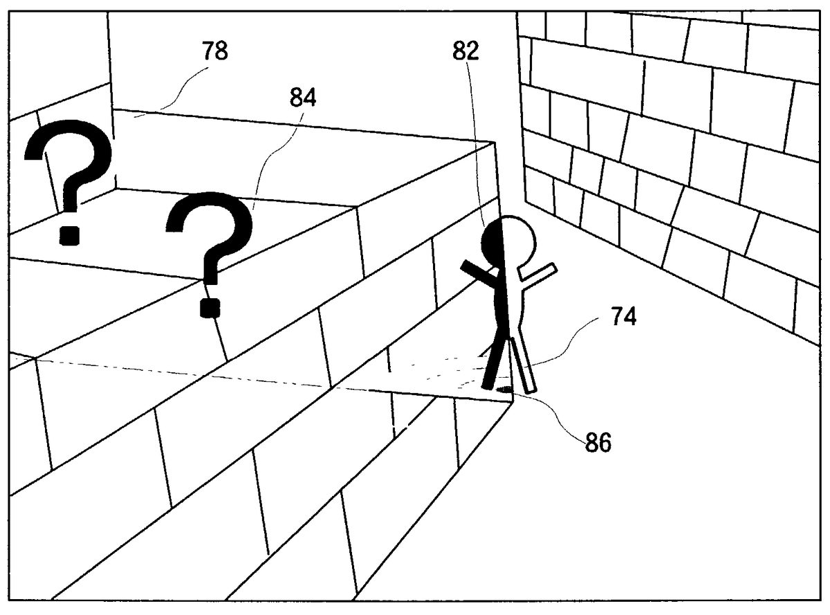
In contrast thereto, when the player character74hides behind the geometry object78in this embodiment, a first mark82(a specific-shaped symbol in order to inform the player of a state that the player character hides behind the object) shown inFIG. 10is displayed on the game screen. This informs the player or user of a state of gameplay in which the player character gets under cover. Accordingly, the player can understand the state that the player character hides behind the object on the basis of the display of the first mark82. Therefore, it is possible to immediately continue the game without any feeling of strangeness.
To this end, in a step S53, the CPU36reads data of the texture72aof the first mark82from the texture data storage area72of the main memory40. The first mark82is a simple color character having the same shape as the player character in this embodiment. It is noted that it is needless to say that such the first mark82may be a symbol in an arbitrary shape, and the shape and the texture may be arbitrarily set similarly to a second mark84and a third mark86described later.
Next, in a step S55, the CPU36renders the first mark texture72aon respective pixels of the frame buffer corresponding to the shape of the player character while ignoring the Z values of respective pixels of the geometry object rendered in the Z buffer50(FIG. 2), i.e., without renewing the Z values of the pixels. Thus, by ignoring (not renewing) the Z values in the respective pixels, the geometry object image and the first mark image becomes an integral image, and in a case the first mark image is closer to a side of the virtual camera than that of the geometry object, the image is rewritten or overwritten, and in a contrary case, the image is not rewritten or overwritten according to the Z test thereafter. That is, when the player character is at the backside of the geometry object, a regular texture of the player character is not overwritten, and therefore, the first mark image is left. On the other hand, when the player character is at the front side of the geometry object, the regular texture of the player character is overwritten. Thus, it is possible to realize a display manner in which one half of the player character which is not hidden by the object is displayed by the regular texture of the player character and other half of the player character which is hidden by the wall object78is displayed by the first mark texture, as to a shape of one player character.
In a step S57corresponding to the second determination mechanism, the CPU36executes the Z test again and compares the arrangement positions between the enemy character and/or the item viewed from the virtual camera (the point of view) and the geometry object. By the Z test, it is determined whether or not the enemy character and/or the item is located at the front side of the geometry object or at the backside thereof every pixel. As a result of the Z test, it is determined whether or not the player character is at the backside of the geometry object in the step S51. That “NO” is determined in the step S57mechanism the enemy character or the item is not at the backside of any geometry object, and in this case, the process is directly returned to the step S35(FIG. 6).
If “YES” is determined in the step S57, it is in a state that the enemy character or the item is at the backside of the wall object78, for example. In this state in a prior art, the enemy character or the item remains at the backside of the geometry object, and thereafter, the enemy character or the item suddenly appears. On the contrary, when the enemy character or the item is at the backside of the wall object78in this embodiment, the second mark (a specific-shaped symbol in order to inform the player of a state that the enemy character or the item is at the backside of the object)84shown inFIG. 10is displayed on the game screen. This informs the player or the user of a state that the enemy character and/or the item are at the backside of the object. Accordingly, the player can understand the state that the enemy character and etc. gets under cover on the basis of the display of the second mark84. Therefore, it is possible to immediately continue the game.
More specifically, in a following step S59, the CPU36reads data of the texture72bfor the second mark84from the texture data storage area72of the main memory40. The second mark84is a mark to inform the player that the enemy character80(FIG. 5) or the item (not shown) is at the backside of the geometry object and has a specific shape and/or a texture. In this embodiment, the second mark texture84is a simple color character and has a question mark (?) shape in English.
Thereafter, in a step S61, the CPU36calculates distance between the player character and the enemy character and/or the item in the projection plane coordinates system. Then, in a step S63, the CPU36changes a color tone of the second mark84according to the distance. Then, in a step S65, the CPU36ignores the Z values similarly to the step S57and renders a second mark texture (and a texture having the changed color tone) into the frame buffer at the position corresponding to the enemy character and/or the item. Accordingly, referring toFIG. 10, for example, a dark colored question mark (?), i.e., the second mark84is displayed at a position of the enemy character or the item being closer to the first mark82for the player character while a light colored second mark84A is displayed at a position of the enemy character or the item being away from the first mark82. Thus, by changing the color tone of the second mark84according to the distances from the player character, the player can know in advance a plurality of enemy characters or items are at the backside of the geometry object and distances between the player character and individual enemy characters or items are different. Accordingly, fear or surprise caused by an appearance of the enemy character from the backside is not given to the player.
Next, in a step S67, the CPU36reads data of the texture72cfor a third mark86(FIG. 10) from the texture data storage area72of the main memory40. The third mark86is a mark to indicate that the player character being at the backside of the geometry object exists on the land or the floor and is a symbol of fourfold circle with gradations in this embodiment. It is noted that the third mark86is arbitrarily changeable in shape and texture.
Finally, in a step S69, the read third mark texture72cis rendered at a position of the player character's feet without renewing the Z value. Thus, the first mark82for the player character is displayed in a state it stands on the third mark86for the land at the backside of the wall object78as shown inFIG. 10. Accordingly, the player or user can know that the player character is at the backside of the wall object78on the land object by viewing the game screen at that time shown inFIG. 10.
It is noted that in a case that the above-described steps S51and S57inFIG. 8are provided, there is a possibility that the steps S53, S55, S59to S69may not be executed, and therefore, it is possible to reduce the load of processing. On the other hand, even if the steps S51and S57are not provided, by executing the steps S54and S55the first mark image can be displayed and by executing the steps S59to S69the second mark image and the third mark image can be displayed. That is, the step S51and/or the step S57may be omitted inFIG. 8.
The rendering process routine of the player character in the step S35(FIG. 6) is described in detail inFIG. 12. In a first step S71inFIG. 12, the CPU36reads texture data corresponding to the player character from the texture data storage area72of the main memory40(FIG. 2andFIG. 3).
Then, in a following step S73, the CPU36refers to the Z values of respective pixels of the Z buffer50(FIG. 2) at positions of corresponding to the player character projected onto the two-dimension projection plane coordinates system converted in the step S15(FIG. 4). Then, in a next step S75, the CPU36determines whether or not the Z value of the pixel to be written is larger than the depth information (Z value) of the player character intended to be written. That is, it is determined whether or not the player character is to be rendered. Accordingly, if “NO” is determined in the step S75, the process directly proceeds to a step S81.
If “YES” is determined in the step S75, the Z value (Z buffer) of that pixel is renewed in a following step S77, and the texture (color information) of the player character is rendered in that pixel in a step S79. Then, the above-described steps S73to S79are repeatedly executed until completion of all pixels is detected in a next step S81, and if the rendering process of all pixels is completed on the display screen of the monitor34, the process returns to the step S37shown inFIG. 6so as to execute the rendering process routine of the enemy character (and item).
The rendering process routine of the enemy character (and/or item) shown in the step S37(FIG. 6) is described in detail inFIG. 13. In a first step S91shown inFIG. 13, the CPU36reads texture data corresponding to the enemy character (and item) from the texture data storage area72of the main memory40(FIG. 2andFIG. 3).
Then, in a next step S93, the CPU36refers to the Z values of respective pixels of the Z buffer50(FIG. 2) at positions corresponding to the enemy character (item) projected onto the two-dimension projection plane coordinates system. Then, in a following step S95, the CPU36determines whether or not the Z value of the pixel to be written is larger than the depth information (Z value) of the enemy character (item) intended to be written. That is, it is determined whether or not the enemy character or the item is to be rendered. Accordingly, if “NO” is determined in the step S95, the process directly proceeds to a step S101.
If “YES” is determined in the step S95, the Z value (Z buffer) of that pixel is renewed in a step S97, and the texture (color information) of the enemy character (item) is rendered in that pixel in a step S99. Then, the above-described steps S93to S99are repeatedly executed until completion of all pixels is detected in the next step S101, and if the rendering process of all pixels on the display screen of the monitor34is completed, the process returns to the step S19shown inFIG. 4.
Although the non-limiting exemplary embodiments of the present invention has been described and illustrated in detail, it is clearly understood that the same is by way of illustration and example only and is not to be taken by way of limitation, the spirit and scope of the present invention being limited only by the terms of the appended claims.
Claims
- A game machine for displaying at least a geometry object and a player character in a game space on the basis of a virtual camera arranged in said game space, comprising: a position determination mechanism for determining positions of said player character and said virtual camera in said game space in response to an operation of the player;a game image producing mechanism for producing a game image in which said geometry object and said player character are viewed from said virtual camera at a determined position;and a first mark image rendering mechanism for rendering a first mark image on an image of said geometry object in said game image without rewriting depth information from the virtual camera in a Z buffer so that at least a position of said player character can be known when said player character hides behind said geometry object.
- A game machine for displaying at least a geometry object and a player character in a game space on the basis of a virtual camera arranged in said game space, comprising: a position determination mechanism for determining positions of said player character and said virtual camera in said game space in response to an operation of the player;a geometry object rendering mechanism for rendering said geometry object by a geometry object image in a frame buffer while writing depth information from said virtual camera to said geometry object in a Z buffer;a first mark image rendering mechanism for rendering said player character by a first mark image in said frame buffer without rewriting the depth information of said Z buffer;and a player character rendering mechanism for rendering said player character by a player character image into said frame buffer while rewriting the depth information of said Z buffer when said player character is closer to the side of said virtual camera than that of said geometry object with referring to the depth information of said Z buffer.
- A game machine for displaying at least a geometry object and a player character in a game space on the basis of a virtual camera arranged in said game space, comprising: a position determination mechanism for determining positions of said player character and said virtual camera in said game space in response to an operation of the player;a game image producing mechanism for producing a game image in which said geometry object and said player character are viewed from said virtual camera at a determined position;a first determination mechanism for determining whether or not said player character hides behind said geometry object;and a first mark image rendering mechanism for rendering a first mark image indicative at least a position of said player character on an image of said geometry object in said game image in response to a determination of said first determination mechanism without rewriting depth information from the virtual camera in a Z buffer.
- A game machine according to claim 1 , wherein said geometry object includes at least a building object for displaying a building and/or a wall in said game space, said first mark image rendering mechanism renders the first mark image on an image of said building object in said game image when said player character hides behind said building object.
- A game machine according to claim 1 , wherein said first mark image includes a specific-shaped first symbol image.
- A game machine according to claim 5 , wherein said first symbol image has the same or similar to said player character in shape and a different from said player character in texture.
- A game program storage device readable by a game machine, tangibly embodying a program of instructions executable by the game machine to make the game machine which displays at least a geometry object and a player character in a game space on the basis of a virtual camera arranged in the game space execute following steps of: a position determination step for determining positions of said player character and said virtual camera in said game space in response to an operation of the player;a game image producing step for producing a game image in which said object and said player character are viewed from said virtual camera at a determined position;and a first mark image rendering step for rendering a first mark image on an image of said geometry object in said game image without rewriting depth information from the virtual camera in a Z buffer such that at least a position of said player character can be known when said player character hides behind said geometry object.
- A game program storage device readable by a game machine, tangibly embodying a program of instructions executable by the game machine to make the game machine which displays at least a geometry object and a player character in a game space on the basis of a virtual camera arranged in said game space execute following steps of: a position determination step for determining positions of said player character and said virtual camera in said game space in response to an operation of the player;a geometry object rendering step for rendering said geometry object by a geometry object image in a frame buffer while writing depth information from said virtual camera to said geometry object into a Z buffer;a first mark image rendering step for rendering said player character by a first mark image in said frame buffer without rewriting the depth information of said Z buffer;and a player character rendering step for rendering said player character by said player character image in said frame buffer while rewriting the depth information of said Z buffer when said player character is closer to the side of said virtual camera than that of said geometry object with referring to the depth information of said Z buffer.
- A game program storage device readable by a game machine, tangibly embodying a program of instructions executable by the game machine to make the game machine which displays at least a geometry object and a player character in a game space on the basis of a virtual camera arranged in said game space execute following steps of: a position determination step for determining positions of said player character and said virtual camera in said game space in response to an operation of the player;a game image producing step for producing a game image in which said object and said player character are viewed from said virtual camera at a determined position;a first determination step for determining whether or not said player character hides behind said geometry object;and a first mark image rendering step for rendering a first mark image indicative at least a position of said player character on an image of said geometry object in said game image in response to a determination of said first determination step without rewriting depth information from the virtual camera in a Z buffer.
Disclaimer: Data collected from the USPTO and may be malformed, incomplete, and/or otherwise inaccurate.