U.S. Pat. No. 7,510,477
CONTROL APPARATUS FOR USE WITH A COMPUTER OR VIDEO GAME SYSTEM
Issue DateDecember 11, 2003
Illustrative Figure
Abstract
A control device for controlling a display of a computer system for use with a video game includes a coordinate control unit for providing information related to a vertical and horizontal tilt of the control device, a mouse control unit for inputting conventional mouse input information, a game control unit for inputting game control information and a controller for processing the information provided by the coordinate control unit, mouse control unit and game control unit. The vertical and horizontal point of view of the user in the video game and/or the vertical and horizontal position of a cursor on the display is determined based on the information related to the vertical and horizontal tilt of the control device. The control device is preferably shaped like a firearm to enhance the realism of the video game, but may be shaped like a conventional game pad.
Description
DETAILED DESCRIPTION The control device10of the present application is particularly well suited for use by a player of a first person “shooter” type video game. In such video games, the player typically is presented with a first person view of an environment in the video game and is asked to aim at and shoot various targets. The user is commonly provided with a crosshair or other target designation, typically, in the center of the display. The point of view of the user in the game typically moves left, right, up, down, etc. based on the input from the computer mouse, keyboard, etc. to allow the user to aim at various targets in the video game. Targeting or aiming is typically accomplished by positioning the crosshair at the desired position, generally using the computer mouse or keyboard to change the point of view of the user in the video game or otherwise position the crosshair on the display in the video game. Shooting the target is typically accomplished by pressing a dedicated shoot button. The dedicated shoot button is typically one of the mouse buttons or a key on the keyboard. Similarly, joysticks may also be used to change the point if view of the user in the game and shooting is typically accomplished by pressing a shoot button, generally on the top of the joystick or on a base of the joystick. A control device that can quickly change the point of view of the user by simply moving the control device provides more intuitive and realistic interaction with the video game. While the control device of the present disclosure is particularly well suited for use in such video games, the control device is preferably operable with any video game and may be used as a mouse in conventional computer ...
DETAILED DESCRIPTION
The control device10of the present application is particularly well suited for use by a player of a first person “shooter” type video game. In such video games, the player typically is presented with a first person view of an environment in the video game and is asked to aim at and shoot various targets. The user is commonly provided with a crosshair or other target designation, typically, in the center of the display. The point of view of the user in the game typically moves left, right, up, down, etc. based on the input from the computer mouse, keyboard, etc. to allow the user to aim at various targets in the video game. Targeting or aiming is typically accomplished by positioning the crosshair at the desired position, generally using the computer mouse or keyboard to change the point of view of the user in the video game or otherwise position the crosshair on the display in the video game. Shooting the target is typically accomplished by pressing a dedicated shoot button. The dedicated shoot button is typically one of the mouse buttons or a key on the keyboard. Similarly, joysticks may also be used to change the point if view of the user in the game and shooting is typically accomplished by pressing a shoot button, generally on the top of the joystick or on a base of the joystick. A control device that can quickly change the point of view of the user by simply moving the control device provides more intuitive and realistic interaction with the video game. While the control device of the present disclosure is particularly well suited for use in such video games, the control device is preferably operable with any video game and may be used as a mouse in conventional computer applications as well. In addition, the control device of the present disclosure is preferably compatible with video game systems such as the SONY PLAYSTATION 2®, a registered trademark of Sony Computer Entertainment, Inc. Similarly, the control device may be utilized with other computer simulations and virtual reality systems such as those commonly used by law enforcement and military agencies as training aids.
A control device10according to a first embodiment of the present invention is described with reference toFIG. 1. A coordinate control unit12is used to input information regarding the desired horizontal and vertical point of view of the user in the video game. More specifically, the coordinate control unit12may be used to provide information related to pitch, the vertical tilt, and yaw, the horizontal tilt, of the control device10to indicate the desired horizontal and vertical point of view of the display of the computer system. A mouse control unit14provides traditional computer mouse input information. A game play control unit16provides additional conventional game play input information. Controller18receives information from the coordinate control unit12, mouse control unit14and game play control unit16and provides game play information to the computer system. In this manner, the control device of the present application includes substantially all of the functionality required to play today's advanced video games.
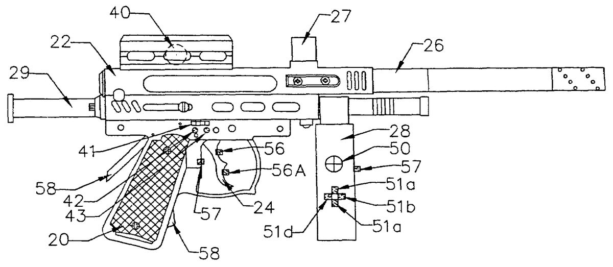
A preferred shape of the control device is described further with reference toFIG. 2. The control device10is preferably shaped as a firearm, that is, the control device10includes a hand grip20positioned below a rear section of a central body22. A trigger24extends down from the central body22in front of the hand grip20. A barrel26extends forward from the central body22. An adjustable fore grip28may extend downward from the barrel26in front of the trigger. For increased reality, the control device10may include a removable stock29, which can be used to steady the control device10against the user's shoulder. This will increase stability of the control device10. The control device10may also be configured as a pistol, another firearm, a pointer or the like. While a firearm is the desired shape of the control device, other shapes may be used, and the invention is not limited to that shape.
The control device10may be shaped as a game pad as illustrated inFIG. 2Afor example. Such game pads are typically substantially U-shaped. The user grasps the device by the free ends200,200aof the U-shape, typically grasping each end with a hand such that the user's finger curl around the free ends. The free ends200,200amay have a slight downward angle. The connected end201of the U-shape typically includes controls for point of view, longitudinal and lateral movement and various game play buttons.
In one embodiment, the coordinate control unit12is integrated with a bipod25or tripod (not shown) attached to the barrel26of the control device10. In an alternative embodiment, a gyroscope device40(seeFIG. 5) similar to that utilized in the gyroscopic control devices described above is mounted on the control device10. In either embodiment, the user is able to play the video game without the need to point the control device at the display and is not confined to the area of a mouse pad or sensor array during game play.
One embodiment of the coordinate control unit12is illustrated in further detail with reference toFIG. 3. As noted above, the coordinate control unit12may be incorporated into a bipod25attached to the barrel26of the control device10. Utilizing this embodiment, the user will preferably mount the bipod25on a surface, such as a table, to stabilize the control device.
The coordinate control unit12may include a y-axis sensor30and an x-axis sensor31that detect movement of the barrel in the y-direction, pitch, and in the x-direction, yaw, respectively. More specifically, the y-axis sensor30and the x-axis sensor31determine the tilt of the barrel26in the y-direction and the x-direction, respectively. A first end of a horizontal shaft32may be attached to the barrel26. A second end of the horizontal shaft32may be connected to an optical encoding disk33. As the barrel26tilts up and down, the horizontal shaft32rotates and the optical encoding disk33rotates with the horizontal shaft32. Optical encoders35may be mounted on a printed circuit board in the main body of the y-axis sensor30. The optical encoders35determine the tilt of the barrel26in the y-direction, that is, up and down, on the rotation of the encoding wheel33. Based on the vertical tilt of the barrel26, the desired vertical point of view of the user in the video game is determined. Similarly, the desired vertical position of a cursor on the display may be determined based on the vertical tilt of the barrel26.
The y-axis sensor30is preferably mounted on a top end of a vertical strut36. The bottom of the vertical strut36may be connected to the x-axis sensor31. More specifically, the bottom end of the vertical strut36may be is connected to a vertical shaft37. The vertical shaft37may be connected to a second optical encoding disk38. As the barrel26moves or tilts horizontally, the vertical shaft37rotates, in turn, rotating the second optical encoding disk38. A second set of optical encoders39may be mounted on a printed circuit board of the main body of the x-axis sensor31to determine the desired horizontal point of view of the user in the video. The x-axis sensor may be used to determine the desired horizontal position of a cursor on the display of the computer system. In this manner, the coordinate control unit12provides information regarding the pitch and yaw of the barrel which is then utilized to determine the desired point of view of the user on the display of the computer system.
Where the control unit is shaped like a game pad, it is unnecessary to implement the coordinate control unit as a bipod as described above. A simple stand that incorporates the x-axis sensor31and y-axis sensor30as described above provides a stable platform on which the rest the control device10while at the same time acting as the coordinate control unit. In this embodiment, the horizontal shaft32is preferably connected to the control device10on a side surface or bottom surface of the connected end201or one of the free ends200,200A of the game pad. The stand may be similar in construction to that illustrated inFIG. 3.
An alternative embodiment of the stand is described with reference toFIG. 3A. Au-shape base300houses the y-axis sensor30and the x-axis sensor31. A connecting strut301is connected at its bottom end to the base300. The control device10is preferably detachably connected to the top end of the connecting strut301. As the control device10tilts up or down, the connecting strut301rotates backward or forward. The y-axis sensor30determines the vertical tilt of the control device based on this rotation in a manner similar to that described above. As the control device10rotates left and right, the x-axis sensor31determines the horizontal tilt of the control device in a manner similar to that described above. The base300may be fastened to a surface using a clip or clamp (not shown) to improve its stability if desired. WhileFIG. 3illustrates a stand used with the fire arm form of the control device10andFIG. 3Aillustrates a stand used with the game pad form of the control device, it is noted that both the fire arm form and the game pad form of the control device may be used with either of the stands illustrated inFIG. 3andFIG. 3A. Alternatively, the connecting strut301may extend out horizontally from the base300.
Alternatively, the coordinate control unit12may be implemented using a gyroscope40(seeFIG. 5) similar to that proposed in the gyroscopic input devices discussed above. Similarly, a gyroscope210may be incorporated into the control device10configured as a game pad as illustrated inFIG. 2Afor example. Where gyroscopes are used, the bipod25or stand is not necessary. In one embodiment, the gyroscope40,210such as the solid state gyroscope mounted on a printed circuit board may be mounted on the control device. As noted previously, gyroscopes have been used for many years in the aviation industry to determine pitch and yaw of aircraft. A solid state gyroscope such as that mentioned above may be utilized to determine the pitch and yaw of the control device10in the present application. The operation of gyroscopes is well known in the art and thus will not be discussed in detail herein. However, a brief discussion of the operation of gyroscopes may be useful in understanding the present invention.
Typically, a gyroscope includes a rotating disk, rotating about an axis of rotation and mounted on a frame rotatable on one or two axes perpendicular to the axis of rotation of the disk. The spinning disk may be a rotating electric motor. The axis of rotation of the motor is typically aligned with the gravity vector. If a force is applied along the axis of rotation of the motor, the force is resisted due to the constant angular momentum of the spinning disk. As a result, the frame will rotate along an axis perpendicular to the axis of rotation of the motor. The rotation of the frame can be monitored. Thus, for example, where a forward tilting force is applied to the gyroscope, a forward force is applied to the top of the axis of rotation of the motor, and a rearward force is applied to the bottom of the axis of rotation of the motor. The constant angular momentum of the spinning motor opposes these forces and the shaft of the motor will rotate in a direction perpendicular to the applied force. Since the frame is free to rotate along the axis perpendicular to the axis of rotation of the motor, the frame rotates. The direction of this rotation depends on the direction of rotation of the spinning motor. The rotation of the frame is proportional to the tilt of the frame forward. Thus, based on the rotation of the frame, it is possible to determine the tilt of the gyroscope. Where the frame is free to rotate about two axes perpendicular to the axis of rotation of the motor, tilting up and down and left and right can be correlated to the rotation of the frame about either axis. Alternatively, a second gyroscope that is mounted on a frame free to rotate in another direction perpendicular to the axis of rotation of the motor may be incorporated to determine tilt in the horizontal direction. In the present application, solid state gyroscopes are preferably used, which do not typically utilized motors as described above, but works on the same principle to provide pitch and/or yaw information.
Utilizing the solid state gyroscope, for example, mounted on the control device10, the vertical and horizontal tilt of the control device can be determined. In this manner, the desired point of view of the user in the video game or the desired position of a cursor on the display of the computer system can be determined. As noted above, there are presently available control devices that utilize gyroscopes to determine the pitch and yaw of the device. The gyroscope used in such a device may be used as the gyroscope of the present invention. The gyroscope210can similarly be mounted on the control device10where the control device is a game pad as noted above. In this case, the gyroscope is preferably mounted in or on the connected end201.
The inclusion of the gyroscope210eliminates the need for a bipod or stand as described above. However, it may be preferable to use the stand in order to aid stability for the user. In addition, use of the stand allows the user to release the control device10without altering the point of view of the user in the video game. Thus, the user is able to take a break from game play without altering his or her view in the game.
The mouse control unit12preferably provides for functions commonly provided by conventional computer mouse and is described with reference toFIG. 4. In a preferred embodiment, a mouse wheel41is mounted on the central body22of the control device10, preferably on a side of the central body above the trigger24. A mouse wheel is commonly incorporated into a conventional computer mouse to allow a user to easily scroll up or down on the display or through a menu illustrated on the display. Similarly, the mouse wheel41of the present disclosure may be utilized to allow the user to scroll through a menu in the video game or any other computer application. Two buttons42,43may be mounted under the mouse wheel41. These buttons may function as the left mouse button42and right mouse button43, commonly incorporated in a computer mouse for making selections on menus, selecting text, calling up menus or the like. In a preferred embodiment, the mouse wheel41, the left mouse button42and right mouse button43are positioned above the trigger24such that they can be easily reached and manipulated by a finger of the user that may also be used to pull the trigger or triggers24of the control device10. The information related to the vertical and horizontal tilt of the control device10may be utilized to provide information regarding the vertical and horizontal position of a cursor on the display such that the control device is capable of performing all the same functions of a computer mouse.
The mouse control unit14may similarly be incorporated into the game pad embodiment if desired. Preferably, the mouse control unit14is mounted on the connected end201of the control pad, on the top surface and substantially centered. In this embodiment, the left mouse button42and right mouse button43are preferably positioned slightly forward of the mouse wheel40as seen inFIG. 2A. Alternatively, the mouse control unit14may be positioned on the top surface of the connected end201of the control pad slightly off center such that the mouse control unit14is easily operated by a thumb of the user. That is the left mouse button42, right mouse button43and mouse wheel41may be positioned above the game play controls52,53,54,55(discussed below) for example and may be easily activated using the same thumb used by the user to activate the game play controls.
The game play control unit16preferably includes game play controls and is illustrated inFIG. 5. Game play controls include controls for inputting information related to other aspects of the video game, for example, character movement in space in the video game, also referred to as longitudinal and lateral movement. A hat switch50and/or a directional switch51are preferably used to control the lateral and longitudinal movement of a character in the game. While the hat switch50and the directional switch51may both be used to control lateral movement, they function in a slightly different manner. The hat switch50typically includes four momentary contact switches with a pad mounted over them. Each momentary contact switch is activated when the user presses down on the section of the pad that is over the respective momentary contact switch. Typically, only one momentary contact switch may be activated at a time, that is, input from more than one momentary contact switch is generally ignored. The directional switch51, however, typically allows input regarding motion in two directions at the same time. The direction switch51preferably includes four independent contact switches51a,51b,51c,51d, generally in a diamond shaped configuration. Each of the independent contact switches51a,51b,51c,51dtypically is used to provide for movement in a particular direction in the video game. Unlike the hat switch50, users are generally able to activate more than one of the contact switches at the same time. More specifically, most video games will allow for movement in the right and forward direction at the same time, for example. The result is diagonal movement in the video game. For example, conventional video games will allow such movement when the keyboard is used as the control device. The independent contact switches51a,51b,51c,51dof the directional switch51may mimic such control from the keyboard. This allows a user of the video game to move the character forward, backward, left, right and diagonally in space in the video game environment. In addition, where the user uses the hat switch50for longitudinal and lateral movement in the vide game, for example, the direction switch51may be used for other functions which increases the flexibility of the control device10. Alternatively, where the direction switch51is used longitudinal and lateral movement in the video game, for example, the hat switch50may be used for other functions.
In addition, game play controls may include a jump button52, a run button53, a crouch button54and a special action button55. These game play controls may be positioned on a side surface of the hand grip20of the control device10such that they are easily operated by the thumb of the user as it wraps around the hand grip (SeeFIG. 5A). A shoot button56may also be considered a game play control, and will be explained in further detail below. Naturally, different games may have different game play options, and thus, it is impossible to list all possible game play controls, however, the control device of the present application is intended to be compatible with most every video game.
A coordinate activation button57is preferably included in the game play control unit16. The activation button57activates the input of information from the coordinate control unit12while depressed. That is, ordinarily the information from the coordinate control unit is not used to control the display of the computer system. In this manner, inadvertent jostling or movement of the control device10by the user is not used to alter the point of view of the user in the video game or the position of the cursor on the display. The user depresses the activation button57when they wish to change the point of view or position of the cursor. Generally, this operation is intuitive to the user in that the user depresses a button when he or she desires to change the display of the computer system and otherwise inadvertent movements do not affect the display of the computer screen. In this manner, a user can reposition the control device for comfort without changing the point of view of the user in the computer game or the position of the cursor on the display. Alternatively, the activation button57may be used as a kill button, that is, the information from the coordinate control unit12is utilized to control the display normally, unless the kill button is depressed. This is slightly less intuitive for a user, however, it sill provides a way for the user to adjust his or her position or grip without affecting the display of the computer system when necessary. In addition, the activation button57may be a lever type switch positioned on the rear or front of the hand grip20.
The game play control unit16may be mounted on the optional fore grip28of the control device10which can be grasped by the user. These controls are preferably positioned on the fore grip28such that they are under the fingers of a user gripping the fore grip. More specifically, the hat switch50or directional switch51may be positioned under or adjacent to the thumb of the user, while the other of the directional or hat switches may be positioned under or adjacent to the fingertips of the user on the hand grip20. The fore grip28is preferably adjustably attachable to the barrel26of the control device10such that it can be moved forward or backward on the barrel in accordance with the preference of the user. The activation button57may be positioned on the fore grip as well (SeeFIG. 5).
Alternatively, the game play control unit16may be positioned on the barrel26of the control device. Preferably, the direction switch51is positioned on one face of the barrel such that the contact switches51a,51b,51c,51dare easily activate by the fingers on the user cradling the barrel (SeeFIG. 7). The hat switch50may be positioned on the opposite face such that it is easily activated by the thumb of the user (SeeFIG. 7A).
As noted above the shoot button56may generally be considered a game play control, however, in a preferred embodiment of the present application, the shoot button is positioned in the trigger24of the control device10. In order to increase the realism of the control device10, it is preferable to mount the shoot button56in the trigger24. A second shoot button56amay also be positioned in the trigger24. Such a second button may be useful where a video game provides a user with two weapons, for example. Alternatively, the trigger24itself may be used as the shoot button56or buttons such that pulling back either trigger corresponds to firing a primary and/or secondary weapon in the video game. In addition, as noted above, a second independent trigger may be included and used as the second shoot button56a.
The game play control unit16may be positioned on the hand grip20of the control device10such that the controls are easily manipulated by the user gripping the hand grip (SeeFIG. 5A). The controls are preferably positioned on the hand grip20such that the buttons52,53,54and55are easily manipulated by a thumb of the user. An embodiment such as this may be particularly useful where the shape of the control device10is a pistol and it would be inconvenient to utilize a fore grip.
As noted above, where the control device10is shaped like a game pad, the game play control unit16, is preferably mounted on the top surface of the connected end201of the game pad and additional game play controls may be mounted on the front surface of the connected end, generally called “shoulder” buttons. In a preferred embodiment, a hat switch50or direction switch51may be positioned on the left side of the connected end201within easy reach of a left thumb of the user. The other game controls,52,53,54and55are preferably positioned on the right side of the connected end201within easy reach of a right thumb of the user. Additional game control may be positioned on the front surface of the connected end201of the game pad. In a preferred embodiment, these game controls include various activity buttons including the shoot button56and the coordinate activation button57, which may be positioned on the right front surface of the connected end such that they can be depressed by the right index finger of the user. Similarly additional game controls202,203may be positioned on the front left surface of the connected end. Further, it is common for game pads to include two small analog or digital joysticks,204,205positioned for easy manipulation by the left and right thumb of the user, respectively. Typically, either of these joysticks204,205or the hat switch or directional button50,51are utilized to change the point of view in the video game, however, since that function is performed based on pitch and yaw information provided by the coordinate control unit12, a different function can be assigned to the control traditional used. Alternatively, one of these controls can be eliminated, although it is advantageous to provide many game controls in order to control modern video games.
In either the firearm embodiment or the control pad embodiment a lever type button58may be included to provide input when pressure is applied. In the firearm embodiment, the lever type button58may be positioned on the rear of the hand grip20such that it can be easily activated by the hand of the user gripping the hand grip. The lever type button may also be positioned on a front side of the hand grip20on the lower portion below the trigger24. In the game pad embodiment, the lever type button is preferably positioned on one of the free ends201,201aof the game pad on either the top or bottom surface thereof. The lever type button58is preferably utilized as the coordinate activation button57. In this case the button57described above may be used to control another function.
The controller18processes information provided by the coordinate control unit12, the mouse control unit14, and the game play control unit16to provide information to the computer system. In a preferred embodiment, the controller18is a microprocessor or microchip. The controller18may be a microchip similar to that utilized in conventional joysticks. Data provided by the coordinate control unit12is utilized to provide information to the computer system related to the desired point of view of the user or desired vertical and horizontal position of the cursor on the display. Information provided by the mouse control unit14is utilized to provide information related to conventional mouse functions such as scrolling through and selecting information displayed on the display. Information provided by the game play control unit16is utilized to provide information related to additional game play options or actions. Using such a controller18, the control device10can be connected to the computer system via a USB port, as is common for conventional joysticks. The control unit10of the present application is compatible with most commercially available joystick microchips. Alternatively, a custom designed microchip maybe utilized as the controller18.
The control device10of the present application may be compatible with conventional joystick or game pad microchips and thus may not require any special software for operation with the computer system. That is, no special drivers may be necessary to integrate the control device with the computer system. Similarly, the control device of the present disclosure is preferably compatible with default software commonly provided with conventional computer systems. Of course, software could be written specifically for the control device10of the present disclosure to enable all buttons, meaning that the user may select what function each of the game play controls of the device controls. This software preferably includes driver software to allow for detection of the device by the operating system of the computer system, for example for detection by Windows®, a registered trademark of Microsoft Corporation. In addition, the software preferably includes programming software to allow the user to program individual controls and to create custom files for individual games, for example.
While the present disclosure discloses specific locations for the various game play controls, it is noted that the game play controls can be configured in most any way, depending on the desire of the user.
The control device10may be connected via a USB cable to a USB port of the computer system as mentioned above, or may be connected via a wireless or optical link. Both wireless and optical links for computer systems are presently available. In this embodiment, a battery may be provided to power the control unit10, such that the control unit can be completely wireless.
The control device may also include a feedback unit19(seeFIG. 1A). The feedback unit provides added elements of reality, by providing tactile feedback to the user. For example, the feedback un it may be utilized to cause a vibration in the control device10when the fire button56is depressed to simulate the recoil of a firearm. Similarly, the control device may be vibrated to simulate an injury to the character in the video game. Such feedback is commonly available in conventional control devices.
The control device10may also include a small display unit27(seeFIG. 2) that replicates or adds to the information provided on the display of the computer system. For example, the display unit may act as a heads up display or HUD to provide certain information to the user that is more easily visible on the display unit than on the display of the computer system. The display unit may also be utilized to recreate the image on the display of the computer screen, such that the user need not necessarily sit in front of the display of the computer screen to play the game.
A method for controlling a display of a computer system for use with a video game according to an embodiment of the present disclosure is described with reference toFIG. 6. At step S60information related to the vertical and horizontal tilt of the control device is received. Mouse input information is received at step S62. Game play information is received at step S64. At step S66, the input information related to vertical and horizontal tilt of the control device, the mouse input information and the game play information are processed and game information is provided to the computer system. The coordinate information may be utilized to provide information related to a desired vertical and horizontal point of view of the user in the video game or to indicate a desire vertical and horizontal position of a cursor on a display f the computer system.
The method ofFIG. 6is substantially implemented by the control device10described above and is not discussed in further detail herein.
While the present application discloses specific embodiments of a method and control device for controlling display of a computer system, it should be understood that many variations are possible. The present application is intended to extend to all such variations permissible under the claims appended hereto.
Claims
- A control device for operation by a user for controlling a display of a computer system for use with a video game, the control device comprising: a housing having a shape adapted to be handled by a user of a video game;a coordinate control unit including a motion sensor included within said housing, said housing being adapted to be handled by the user for generating input information related to a vertical and a horizontal tilt of the control device;a game play control unit included within said housing adapted to be handled by the user for generating game play input information;and a controller adapted to process the input information from the coordinate control unit to provide to the computer system point of view information of an avatar in a video game virtual environment, and adapted to process said input information from the game play control unit to provide to the computer system game play information representative of at least changes in latitudinal and longitudinal position of the avatar in the video game virtual environment, thereby creating a unified representation of changes of the point of view of the avatar within the video game virtual environment, which unified representation encompasses both horizontal and vertical changes of the avatar's point of view within the video game virtual environment in response to handling by the user of the control device while not within the video game virtual environment, as well as latitudinal and longitudinal changes of the avatar's position as expressed within the point of view of the video game virtual environment, in response to handling by the user of the game play control unit while not within the video game virtual environment.
- The control device of claim 1 , wherein the housing of said control device has a shape substantially similar to a firearm comprising: a central body, a handgrip extending downward from a rear section of the central body, and a barrel extending longitudinally forward from the central body.
- The control device of claim 2 , wherein the coordinate control unit further comprises: a y-axis sensor adapted to input information regarding a tilt of the barrel of the control device in a vertical direction;and an x-axis sensor adapted to input information regarding a tilt of the barrel of the control device in a horizontal direction.
- The control device of claim 3 , wherein the y-axis sensor further comprises: a horizontal shaft attached to a side of the barrel that rotates as the barrel is tilted upward and downward;a first optical disk attached to the horizontal shaft such that the optical disk rotates with the horizontal shaft;and at least one optical encoder adapted to correlate rotation of the optical disk to vertical tilt of the barrel to provide information indicating a desired vertical point of view of the avatar in the video game virtual environment.
- The control device of claim 3 , wherein the x-axis sensor further comprises: a vertical shaft connected to the y-axis sensor such that the vertical shaft rotates as the barrel is tilted left and right;a second optical encoder disk attached to the vertical shaft such that the second optical disk rotates with the vertical shaft;and at least one second optical encoder adapted to correlate the rotation of the second optical disk to a horizontal tilt of the barrel to provide information indicating a desired horizontal point of view of the avatar in the video game virtual environment.
- The control device of claim 1 , wherein the coordinate control unit further comprises: at least one gyroscope adapted to provide input information regarding the vertical and horizontal tilt of the control device in order to provide information regarding a desired vertical and horizontal point of view of the avatar in the video game virtual environment.
- The control device of claim 1 , wherein the coordinate control unit further comprises: at least one gyroscope adapted to provide information regarding the vertical and horizontal tilt of the control device in order to provide information regarding a desired vertical and horizontal position of a cursor on the display of the computer system.
- The control device of claim 1 , further including a mouse type of control unit adapted to be operated by the user in order to generate computer mouse type input information, wherein the mouse type control unit comprises: a rotatable mouse wheel adapted to provide information upon rotation to cause scrolling up or down on the display;a left mouse button adapted to provide information regarding selections of the user;and a right mouse button adapted to provide information regarding other selections of the user.
- The control device of claim 8 , further including: a trigger extending downward from the central body in front of at least a portion of the handgrip;and wherein the mouse wheel, the left mouse button and the right mouse button are mounted on a side of the central body of the control device such that positioning a finger of the user proximate to the trigger operates the mouse wheel, left mouse button and right mouse button.
- The control device of claim 2 , wherein the game play control unit comprises: a directional controller adapted to generate input information regarding longitudinal and lateral movement in space;a plurality of buttons adapted to provide information regarding a plurality of actions performed on the display, the plurality of actions including two or more of running, crouching, jumping and special actions;and a coordinate activation button adapted to selectively enable and disable input of information from the coordinate control unit to the computer system.
- The control device of claim 10 , wherein the plurality of buttons are positioned on the handgrip of the control device such that the plurality of buttons are operable by fingers of the hand of the user gripping the handgrip.
- The control device of claim 11 , further comprising: a foregrip, positioned forward from the handgrip of the weapon, wherein the directional controller is positioned on the foregrip and is operable by a thumb and fingers of a another hand of the user gripping the foregrip.
- The control device of claim 11 , wherein the directional controller is positioned on the barrel of the control device.
- The control device of claim 2 , further including a trigger extending downward from the central body in front of at least a portion of the handgrip;and wherein the game play control unit further comprises a shoot button mounted on the trigger of the control device.
- The control device of claim 2 , further comprising a removable shoulder stock extending behind the central body of the control device and adapted to steady the control device against a shoulder of the user.
- The control device of claim 1 , further comprising a display unit mounted on the control device to provide additional image information to a user of the control device.
- The control device of claim 1 , further comprising a feedback unit adapted to provide tactile feedback to a user of the control device.
- A method for allowing a user to control a video game display of a computer system, comprising: providing a video game control device with a housing having a shape adapted to be handled by a user of a video game;generating within the housing information from a motion sensor which is included within a coordinate control unit portion of the video game control device, said information being related to a vertical and a horizontal tilt of the video game control device and being representative of point of view information of an avatar in a displayed video game virtual environment;generating within the housing information from a game play control unit portion of the video game control device, said information being representative of at least changes in latitudinal and longitudinal position of the avatar in the displayed video game virtual environment;and providing game information for controlling the video game virtual environment display of the computer system based on information generated by the coordinate control unit and providing game information for controlling the video game virtual environment display of the computer system based on information generated by the game play control unit , thereby creating a unified representation of changes of the point of view of the avatar within the video game virtual environment, which unified representation encompasses both horizontal and vertical changes of the avatar's point of view within the video game virtual environment in response to handling by the user of the control device while not within the video game virtual environment, as well as latitudinal and longitudinal changes of the avatar's position as expressed within the point of view of the video game virtual environment, in response to handling by the user of the game play control unit while not within the video game virtual environment.
- The method of claim 18 , wherein the control device has a shape substantially similar to a firearm comprising: a central body;a handgrip extending downward from a rear section of the central body;a barrel extending longitudinally forward from the central body;and a trigger extending downward from the central body in front of the handgrip, and where: the fingers or thumb of one hand of the user, positioned on one of the handgrip, foregrip or barrel, operate one or more buttons adapted to provide input information regarding longitudinal and lateral position of the avatar in the displayed video game virtual environment, while the fingers or thumb of the other hand of the user, positioned on a different one of the handgrip, foregrip or barrel, operate one or more buttons adapted to provide input information regarding a plurality of actions performed by the avatar in the displayed video game virtual environment, the plurality of actions including one or more of running, crouching, jumping and selecting weapons, wherein both hands, in addition to providing the above-noted operation, provide stability to the device with respect to the vertical and horizontal tilt of the control unit, as well as reducing fatigue in wielding the control device in a manner similar to a real firearm.
- The method of claim 19 , wherein the step of generating information related to the vertical and horizontal tilt of the control device comprises: generating information regarding a tilt of the barrel relative to a centered vertical position of the control device from a y-axis sensor;and generating information regarding a tilt of the barrel relative to a centered horizontal position from an x-axis sensor.
- The method of claim 20 , wherein the step of generating information from the y-axis sensor further comprises: attaching a horizontal shaft to a side of the barrel that rotates as the barrel is tilted upward and downward;connecting a first optical disk attached to the horizontal shaft such that the optical disk rotates with the horizontal shaft;and providing at least one optical encoder adapted to correlate rotation of the optical disk to vertical tilt of the barrel to provide information indicating a desired vertical point of view of the avatar in the video game virtual environment.
- The method of claim 21 , wherein the step of generating information from the x-axis sensor further comprises: connecting a vertical shaft to the y-axis sensor such that the vertical shaft rotates as the barrel is tilted left and right;connecting a second optical encoder disk attached to the vertical shaft such that the second optical disk rotates with the vertical shaft;and providing at least one second optical encoder adapted to correlate the rotation of the second optical disk to a horizontal tilt of the barrel to provide information indicating a desired horizontal point of view of the avatar in the video game virtual environment.
- The method of claim 18 , wherein the step generating information from the coordinate control unit further comprises: attaching at least one gyroscope to the control device;and generating information regarding the vertical and horizontal tilt of the control device from the gyroscope in order to provide information regarding the desired vertical and horizontal point of view of the avatar in the video game virtual environment.
- The method of claim 19 , including the further step of providing a mouse control unit with the video game control device for generating mouse control information, wherein the step of generating mouse control information comprises: generating information related to scrolling up and down on the video game display;generating information regarding selections of a user from a left mouse button;and generating information regarding other selections of a user from a right mouse button.
- The method of claim 24 , wherein the left mouse button and the right mouse button are mounted on a side of the central body of the control device such that positioning a finger of a user proximate to the trigger operates the mouse left mouse button and right mouse button.
- The method of claim 19 , wherein the step of generating information from a game play control unit comprises: generating input information regarding longitudinal and lateral movement of a character on the display in space from a direction control unit;generating information regarding a plurality of actions performed by the character on the display, from a plurality of controls;and generating activation information from a coordinate activation button to enable input of information from the coordinate control unit.
- The method of claim 26 , wherein the plurality of controls are positioned on the hand grip of the control device such that at least one of the controls is operable by a thumb of the user gripping the handgrip.
- The method of claim 27 , wherein the direction control unit is positioned on a fore grip, extending down from the barrel of the control device and is operable by at least one of a thumb and fingers of a second hand of the user gripping the fore grip.
- The method of claim 28 , wherein the plurality of controls includes a shoot button mounted on the trigger of the control device.
- The method of claim 19 , wherein the control device further comprises a removable shoulder stock extending behind the central body of the control device and adapted to steady the control device against a shoulder of the user.
- The method of claim 18 , further comprising receiving additional image information to be displayed to a user via a display unit.
- The method of claim 18 , further comprising receiving feedback information for providing tactile feedback to a user via a feedback unit.
- A control device for operation by a user for controlling a display of a computer system for use with a video game, the control device comprising: a housing having a shape adapted to be handled by a user of a video game;a coordinate control unit including a motion sensor included within said housing, said housing being adapted to be handled by the user for generating input information related to a vertical and a horizontal tilt of the control device;a game play control unit included within said housing adapted to be handled by the user for generating game play input information;and a controller adapted to process the input information from the coordinate control unit to provide to the computer system point of view information of an avatar in a video game virtual environment, and adapted to process said input information from the game play control unit to provide to the computer system game play information representative of at least changes in latitudinal and longitudinal position of the avatar in the video game virtual environment, thereby creating a unified representation of changes of the point of view of the avatar within the video game virtual environment, which unified representation encompasses both horizontal and vertical changes of the avatar's point of view within the video game virtual environment in response to handling by the user of the control device while not within the video game virtual environment, as well as latitudinal and longitudinal changes of the avatar's position as expressed within the point of view of the video game virtual environment, in response to handling by the user of the game play control unit while not within the video game virtual environment.
- The control device of claim 33 , wherein the control device is substantially u-shaped comprising: a first open end;a second open end;and a connected end connecting the first open end and the second open end.
- The control device of claim 34 , wherein the coordinate control unit further comprises: a y-axis sensor adapted to input information regarding a tilt of the control device in a vertical direction;and an x-axis sensor adapted to input information regarding a tilt of the control device in a horizontal direction.
- The control device of claim 35 , wherein the y-axis sensor further comprises: a horizontal shaft attached to a side of the control device that rotates as the control device is tilted upward and downward;a first optical disk attached to the horizontal shaft such that the optical disk rotates with the horizontal shaft;and at least one optical encoder adapted to correlate rotation of the optical disk to vertical tilt of the control device to provide information indicating a desired vertical point of view of the avatar in the video game virtual environment.
- The control device of claim 36 , wherein the x-axis sensor further comprises: a vertical shaft connected to the y-axis sensor such that the vertical shaft rotates as the control device is tilted left and right;a second optical encoder disk attached to the vertical shaft such that the second optical disk rotates with the vertical shaft;and at least one second optical encoder adapted to correlate the rotation of the second optical disk to a horizontal tilt of the control device to provide information indicating a desired horizontal point of view of the avatar in the video game virtual environment.
- The control device of claim 35 , wherein the y-axis sensor and the x-axis sensor are positioned in a substantially u-shaped base such that the y-axis sensor detects rotation of a connecting member extending vertically from the base to the control device forward and backward to determine the vertical tilt of the control device and the x-axis sensor detects rotation of the connecting member left and right to determine the horizontal tilt of the control device.
- The control device of claim 33 , wherein the coordinate control unit further comprises: at least one gyroscope adapted to provide information regarding the vertical and horizontal tilt of the control device in order to provide information regarding a desired vertical and horizontal point of view of the avatar in the video game virtual environment.
- The control device of claim 34 , further including a mouse control unit adapted to generate computer mouse input information, wherein the mouse control unit comprises: a rotatable mouse wheel adapted to provide information upon rotation to cause scrolling up or down on the display;a left mouse button adapted to provide information regarding selections of a user;and a right mouse button adapted to provide information regarding other selections of a user.
- The control device of claim 40 , wherein the mouse wheel, the left mouse button and the right mouse button are mounted in a substantially centered position on a top surface of the connected end of the control device.
- The control device of claim 40 , wherein the mouse wheel, the left mouse button and the right mouse button are mounted in an off centered position on a top center of the connected end of the control device.
- The control device of claim 34 , wherein the game play control unit comprises: a directional controller adapted to input information regarding longitudinal and lateral movement in space positioned on the left side of the top surface of the connected end such that the directional controller is easily manipulated by the left thumb of the user;a plurality of buttons adapted to provide information regarding a plurality of actions performed on the display, the plurality of actions including running, crouching, jumping and selecting weapons and positioned on the right side of the top surface of the control device such that the plurality of buttons are easily manipulated by the right thumb of the user;and a coordinate activation button adapted to enable input of information from the coordinate control unit while depressed and positioned on a front surface of the connected end of the control device.
- The control device of claim 33 , further comprising a display unit mounted on the control device to provide additional image information to a user of the control device.
- The control device of claim 33 , further comprising a feedback unit adapted to provide tactile feedback to a user of the control device.
Disclaimer: Data collected from the USPTO and may be malformed, incomplete, and/or otherwise inaccurate.