U.S. Pat. No. 7,458,893
BILLIARD GAME INPUT DEVICE, BILLIARD GAME SYSTEM, GAME INPUT DEVICE, AND COMPUTER PROGRAM
AssigneeKonami Group Corp
Issue DateNovember 21, 2002
Illustrative Figure
Abstract
Provided is an input device for a billiard game comprising: a simulative ball provided as an object to be shot by a player; a link portion having a ball axis on which the simulative ball is mounted; a support portion for movably supporting the link portion; and a sensor for outputting a signal that corresponds to an operation of the link portion, wherein at least either one of rotational motion of the simulative ball around an axle of a ball axis and linear motion of the simulative ball in a predetermined range along an axial direction of the ball axis is permitted.
Description
DESCRIPTION OF THE PREFERRED EMBODIMENT FIG. 1is a perspective view showing an appearance of a billiard game machine according to one embodiment of the present invention. This billiard game machine1(hereinafter, simply referred to as a game machine) is composed as a commercially available arcade game machine installed in an amusement space of a so called game shop or the like. The game machine1has a chassis2; a monitor3mounted at the upper part of the chassis2; and speakers4,4mounted upwardly thereof. At the frontal side of the chassis2, there is provided a table portion5simulating a table of an actual billiard board. A coin entry port5aand a return port5bare provided in front of the table portion5. At the center of an upper face5cof the table portion5, a stuff cloth6is laid from the frontal side to the depth. An explanatory panel7and a control panel8are provided respectively at the right and left sides thereof. Five operating buttons9ato9econsisting of push button switches are provided on the control panel8. The number and location of the operating buttons may be changed as required. In an example ofFIG. 1, an OK button9ais provided at the center of the panel, and an up button9b, a down button9c, a left button9d, and a right button9eare provided so as to surround the OK button9alongitudinally and transversely. An input device10according to the present invention is provided at the rear of the table portion5. The input device10has: a base portion11disposed so as to be embedded in the table portion5; and a top portion12provided so as to cover the base portion11. An upper face11aof the base portion11is identical to an upper face5cof the table portion5(precisely identical to the stuff cloth6), and a table face Ts is composed of these upper faces5cand11a. A space13is provided between the table face Ts and top portion12, and a simulative ball14is ...
DESCRIPTION OF THE PREFERRED EMBODIMENT
FIG. 1is a perspective view showing an appearance of a billiard game machine according to one embodiment of the present invention. This billiard game machine1(hereinafter, simply referred to as a game machine) is composed as a commercially available arcade game machine installed in an amusement space of a so called game shop or the like. The game machine1has a chassis2; a monitor3mounted at the upper part of the chassis2; and speakers4,4mounted upwardly thereof. At the frontal side of the chassis2, there is provided a table portion5simulating a table of an actual billiard board. A coin entry port5aand a return port5bare provided in front of the table portion5.
At the center of an upper face5cof the table portion5, a stuff cloth6is laid from the frontal side to the depth. An explanatory panel7and a control panel8are provided respectively at the right and left sides thereof. Five operating buttons9ato9econsisting of push button switches are provided on the control panel8. The number and location of the operating buttons may be changed as required. In an example ofFIG. 1, an OK button9ais provided at the center of the panel, and an up button9b, a down button9c, a left button9d, and a right button9eare provided so as to surround the OK button9alongitudinally and transversely.
An input device10according to the present invention is provided at the rear of the table portion5. The input device10has: a base portion11disposed so as to be embedded in the table portion5; and a top portion12provided so as to cover the base portion11. An upper face11aof the base portion11is identical to an upper face5cof the table portion5(precisely identical to the stuff cloth6), and a table face Ts is composed of these upper faces5cand11a. A space13is provided between the table face Ts and top portion12, and a simulative ball14is disposed there. The space13opens forwardly of the chassis2. A player can shoot the simulative ball14by inserting a cue (not shown) into the space13through its opening. As a cue of the game machine1, a real cue used in actual billiard may be used or its substitute may be used. Any rod shaped member extending straightway can be used as a cue.
FIG. 2is a perspective view showing the top portion12of the input device10, a part of which is shown in a cutout manner.FIG. 3is a perspective view showing an internal structure of the base portion11. The base portion11has a main body15; and a support mechanism16disposed in the inside of the main body15, the support mechanism16supporting the simulative ball14. The main body15has a substrate17, wall plates18. . .18suitably mounted on the substrate17, and a table top19mounted at the upper end of the wall plate18. An extraction window19ais provided on the table top19. This extraction window19ais covered with a semitransparent cover20(refer toFIG. 5).
The support mechanism16movably supports the simulative ball14between a shot position on the table top19and a standby position that falls at the rear of the game machine1passing through an opening19bof the table top19, as indicated by the arrow inFIG. 2andFIG. 3. In addition, this mechanism16restores the simulative ball14from the standby position to the shot position. A detailed description of the support mechanism16is given below.
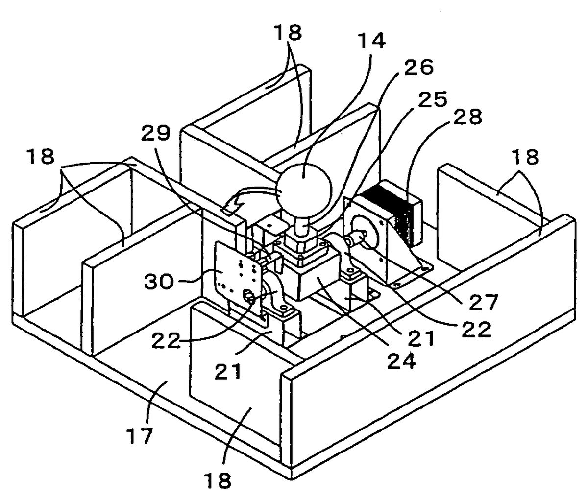
As shown inFIG. 4andFIG. 5, the support mechanism16has: a pair of bearings22,22mounted on a substrate17via a bracket21; a bearing base24turnably supported by these bearings22,22via spindles23,23; a bearing25fixed to the upper end of the bearing base24; and a ball axis26inserted into the bearing25. The simulative ball14is fixed at the tip end of the ball axis26, and the center of the simulative ball14is positioned on the axle of the ball axis26. A total mass of the simulative bail14and ball axis26is equal to that of the cue ball used in actual billiard. In addition, the diameter of the simulative ball14is equal to that of the cue ball used in actual billiard. A material for the simulative ball14may be the same as that for actual cue ball.
As is evident fromFIG. 5, the ball axis26has: an engagement portion26athat is slidable along the axial direction and rotatably engaged around the axle relevant to the bearing25; a large diameter portion26bhaving its diameter greater than the engagement portion26a, and a flange26cfixed at the lower end of the engagement portion26a. A stepped portion between the large diameter portion26band the engagement portion26acomes into contact with the upper end of the bearing25, whereby a drop of the ball axis26is inhibited. The engagement portion26ais formed to be longer than engagement length of the bearing25. Therefore, the simulative ball14can be pulled up together with the ball axis26until the flange26ccomes into contact with the upper end of the bearing base24. The simulative ball14and ball axis26can rotate integrally relevant to the bearing25.
In this manner, the simulative ball14is provided movably in the axial direction of the ball axis26supporting the ball (refer to the arrow LM ofFIG. 5) and rotatably round the axle of the ball axis26(refer to the arrow RM). Thus, when a player shoots the simulative ball14off its core in order to apply a so called spin, the simulative ball14can escape vertically or rotate according to the degree of displacement of such a shot. In this manner, the feeling of shooting can be simulated to the feeling when an actual cue ball has been shot in spite of a construction in which the simulative ball14is constrained by the support mechanism16.
As shown inFIG. 4, the support mechanism16has a pair of spindles23and a motor28connected via a coupling27. In this manner, the simulative ball14can be restored from a standby position P2(a position indicated by a virtual line inFIG. 5) to a shot position P1(a position indicated by a solid line inFIG. 5) by the power of the motor28. In addition, a detection plate29is mounted on a side face of the bearing base24ofFIG. 4(left side face ofFIG. 4). As shown inFIG. 6, a sensor support plate30is mounted on the bracket21, and three photo sensors31to33are mounted on the sensor support plate30. These photo sensors31to33have slit shaped sensing portions31a,32a, and33a. The simulative ball14rotates around the spindle23, whereby the detection plate29can be protruded or recessed relevant to the sensing portion31a,32a, or33aof the photo sensor31,32, or33. When the simulative ball14is set at its shot position, the detection plate29is inserted into the sensing portion31aof a first photo sensor31, whereby an output signal of the first photo sensor31is set to ON, and output signals of the other photo sensors32and33are set to OFF. When the simulative ball14starts rotation toward its standby position, the detection plate29passes through the sensing portion32aof the second photo sensor32, while the output signal of the photo sensor32is set to ON. When the simulative ball14reaches its standby position, the detection plate29is inserted into the sensing portion33aof the third photo sensor33, and the output signal of the photo sensor33is set to ON. The first photo sensor31functions as a simulative ball operation detecting device and a speed information detecting device. The second photo sensor32functions as a speed information detecting device. Other sensors such as a proximity switch may be used instead of the photo sensors31to33. However, in order to guarantee smooth movement of the simulative ball14, it is desirable that a sensor be of non-contact type.
In the above support mechanism16, the bearings22,22function as a support portion16a, and spindles23,23, bearing base24, bearing25, ball axis26, and detection plate29function as a link portion16b, respectively. A bearing portion16cis composed of the bearing base24and bearing25. In addition, the large diameter portion26bof the ball axis26and the flange26ccorrespond to a stopper device, the motor28corresponds to a driving device, a pad34corresponds to a buffering device, and an illumination lamp35corresponds to an illumination device, respectively.
As shown inFIG. 2, a top portion12has: a hood36that covers a space13formed between the top portion12and an upper face11a(corresponding to a table face) of a base portion11; and a pair of image sensors (image acquiring device)37,37incorporated in the hood36. The image sensor37scans a cue shot toward the simulative ball14, and outputs the scanned image as image data of predetermined dot number and predetermined gradations. A rectangle-shaped, punched hole36arestricting the viewing field of each image sensor37to a predetermined range, for example, is formed at the hood36. The hood36functions as a device for suppressing an effect of external light on the range scanned by the image sensor37. In addition, this hood36also functions as a device for restricting the range of access of the cue to the simulative ball14so that the cue shooting the simulative ball14always passes through the range detected by the image sensors37,37.
A contrast between a cue when seen from the image sensor37and a cover20of its background increases due to the illumination light from the above described illumination lamp35, and the cue recognition rate is improved. The cover20scatters illumination light from the illumination lamp35, and the brightness of the cue background portion is uniformed. As an image sensor37, there can be utilized a 32 dots×32 dots version of an artificial retina LSI available from Mitsubishi Electric & Machinery Co., Ltd., for example.
FIG. 7AandFIG. 7Bshow a relationship between disposition and viewing field of a pair of image sensors37.FIG. 7Ais a view showing a state seen from the frontal side of the game machine1.FIG. 7Bis a view showing a state seen from the upward direction. The viewing fields (scanning range)40,40of each image sensor37are as shown by hatching, and the superimposed range of the viewing fields of both sensors37is obtained as a cue detection range41. As shown inFIG. 7A, the image sensors37,37are disposed so that the respective optical axes AX1, AX2pass through the center position of the simulative ball14viewed from the frontal side of the game machine1and the optical axes AX1, AX2are inclined at an angle θ laterally equal to each other relevant to a vertical line V passing through the center of the simulative ball14. The angle θ may be properly set, and is set at 45 degrees, for example. A viewing angle φ of each image sensor37is set to 40 degrees, for example. In addition, as shown inFIG. 7B, the image sensors37,37are disposed at the same position with respect to the forward/backward direction of the game machine1, and the respective viewing fields40extend forwardly of the game machine1(to the lower side ofFIG. 7B) from the vicinity of the frontal end of the simulative ball14. The dispositions ofFIG. 7AandFIG. 7Bare provided as one example, and various modifications can occur. For example, one image sensor37may be disposed from the top of the simulative ball14to the vertical downward direction, and the other image sensor37may be disposed from the left side or right side of the simulative ball14to the horizontal direction.
FIG. 8is a block diagram depicting a construction of a control system in the game machine1. The game machine1comprises a CPU50composed of microprocessors. In the CPU50, as an input device, there are provided: the above described operating buttons9ato9c; photo sensors31to33; image sensors37,37; and a coin authentication unit51. The coin authentication unit51judges the truth or falseness of coin entered through a coin entry port5a(refer toFIG. 1). In the case where a true coil is entered, this unit outputs a predetermined coin entry signal to the CPU50. When a signal indicating that a predetermined number of true coins have been entered is outputted from the coin authentication unit51, a predetermined billiard game is started under the control of the CPU50. An interface unit is properly provided between each of these input devices and the CPU50, although not shown.
In addition, to the CPU50, there are connected: a ROM52having recorded therein a program for controlling basic operations such as startup processing of the game machine1; a work ROM53for providing a work region to the CPU50; a game program storage unit54having recorded therein a variety of programs and data required to execute a predetermined billiard game in the game machine1; an image processing unit55for depicting an image on a video memory (not shown) in accordance with an instruction from the CPU50, and converting the depicted image into a video reproduction signal, thereby outputting the converted video reproduction signal to a monitor3; a sound processing unit56for carrying out pronunciation processing according to an instruction from the CPU50, thereby outputting a sound reproduction signal to a speaker4; and a motor drive unit57for driving a motor28of the input device10in accordance with an instruction from the CPU50. For the game program storage unit54, there can be used a variety of computer readable storage media including a magnetic storage medium such as a nonvolatile semiconductor storage device or a hard disk, for example, or an optical storage medium such as DVD-ROM or CD-ROM.
Now, a variety of processing functions executed by the CPU50based on a program recorded in the game program storage unit54will be described here.
FIG. 9andFIG. 10are flowcharts showing procedures for cue detection processing executed by the CPU50to detect a cue based on an image outputted from the image sensor37. This cue detection processing is repeatedly executed in a predetermined cycle (for example, a cycle of 60 times per second). This detection processing includes: processing for acquiring a two-dimensional coordinate of a cue image included in a two-dimensional image acquired by each image sensor37(steps S1to S8); and processing for obtaining a three-dimensional coordinate concerning two typical points on a cue based on the acquired two-dimensional coordinate (steps S11to S18).
An object of the processing for acquiring the two-dimensional coordinate of the cue is to obtain an image103on a difference between a base image100shown inFIG. 11Aand an image101including a cue image102, and then, obtain a two-dimensional coordinate of the cue image102in the image103. As its preprocessing, this processing further includes processing for serially updating the base image100(steps S2to S4). Hereinafter, a description will be given in order.
In cue detection processing, first, a two-dimensional image scanned by one image sensor37is acquired (step S1). Next, a difference between the acquired image and an image of the same sensor37, the image being acquired during previous processing, is acquired (step S2). For example, if an image101A ofFIG. 11Dis obtained as a previous image, and an image101ofFIG. 11Eis obtained as a current image, an image104on a difference as shown inFIG. 11Fis acquired. The images101A and101ofFIG. 11DandFIG. 11Einclude a background105and a cue image102. In the differential image104, an image106corresponding to the range in which the tip end of the cue has moved between the previous processing and the current processing is acquired.
Then, the processing goes to the step S3ofFIG. 9in which a position of a tip end102a(refer toFIG. 11EandFIG. 11F) of a cue image102in the currently scanned image101is specified based on the differential image104. Then, the base image100is updated relevant to a range (enclosed in thick line frame inFIG. 11E) which is more distant than the tip end (a point on the center line of the cue)102aof the cue image102(step S4). Namely, of the base image100, the range which is more distant than the tip end102aof the cue is replaced with the currently acquired image101.
The base image100is thus replaced because the cue recognition capability is improved by maximally eliminating an effect which a brightness change in the cue detection range41imparts to gradation of an image acquired by the image sensor37. In addition, only a portion which is more distant than the tip end of the cue is updated because any other portion includes the cue image102, and thus, cannot be used as the base image100.
After updating the base image100, the cue image102is detected from a difference between the current image101and the base image100(step S5). Then, a predetermined position of the detected cue, i.e., a coordinate of a tip end102aand a rear end102bof the cue image102is acquired (step S6). The coordinate acquired here is a coordinate in a two-dimensional coordinate system set on the plane of each image101.
In the next step S7, it is discriminated whether or not images obtained from two image sensors37have been processed. If it is negatively discriminated, an image of the other image sensor37is acquired (step S8). Then, the processing returns to the step S2. When it is affirmatively discriminated in the step S7, the processing goes to the step S11of theFIG. 10.
In the step S11ofFIG. 10, a two-dimensional coordinate of the tip end102of the cue acquired in the step S6is selected as a processing target. The two-dimensional coordinates exist one by one relevant to each image sensor37. By the processing of the subsequent steps S12to S16, a three-dimensional coordinate of typical points of the cue is computed based on a two-dimensional coordinate to be processed. Hereinafter, the processing of the steps S12to S16will be described with reference toFIG. 12AandFIG. 12B.
FIG. 12Ashows a state in which a cue45is shot toward the simulative ball14, wherein a three-dimensional coordinate system x-y-z is set with respect to the detection range41. For example, when a center14aof the simulative ball14is defined as an origin, x-axis, y-axis, and z-axis are set in the forward/backward direction, transverse direction, and vertical direction of the game machine1, respectively. The viewpoints VP1and VP2of each image sensor37are constant, and the three-dimensional coordinates (x1, y1, z1) and (x2, y2, z2) of these viewpoints VP1and VP2are already known. In addition, the focal distance of each image sensor37is also constant. Further, the image101shown inFIG. 11Bcorresponds to, inFIG. 12A, a projected image onto scanning planes PL1and PL2of a predetermined size, the planes being distant from the viewpoints VP1and VP2of each image sensor37by a focal distance and being orthogonal to optical axes AX1and AX2of each image sensor37. In other words, each image sensor37scans an image obtained by projecting the cue45onto the scanning plane PL1and PL2corresponding to itself, and outputs data on the scanned image.
The three-dimensional coordinate of cross points CP1and CP2between the optical axes AX1, AX2and the scanning plane PL1, PL2can be obtained from the three-dimensional coordinate of the viewpoints VP1and VP2and the focal distance of each image sensor37. Therefore, a relationship between the two-dimensional coordinate and the three-dimensional coordinate on the scanning planes PL1and PL2of the cross points CP1and CP2can also be obtained in advance. Based on the relationship between the two-dimensional coordinate and the three-dimensional coordinate on the scanning planes PL1and PL2of the cross points CP1and CP2, the two-dimensional coordinate of all points on the image101ofFIG. 11Bcan be converted into the three-dimensional coordinate in the three-dimensional coordinate system ofFIG. 12A.
In the processing ofFIG. 10, in the case where the two-dimensional coordinate of the tip end102aof the cue image102has been selected in the step S11, the two-dimensional coordinate of the tip end102athereof is first converted into the three-dimensional coordinate. Then, an equation expressing straight lines L1and L2connecting the tip end102aand the viewpoints VP1and VP2each is obtained (step S12). Next, it is judged whether or not the straight lines L1and L2have a cross point (step S13). When it is affirmatively judged, the three-dimensional coordinate of the cross point is determined as a three-dimensional coordinate of the tip end45aof the cue45(step S14). On the other hand, if it is negatively judged, a perpendicular line L3common to two straight lines L1and L2is obtained as shown inFIG. 12B(step S15). Then, the three-dimensional coordinate of a middle point MP of the perpendicular line L3is determined as a three-dimensional coordinate of the tip end45aof the cue45(step S16). After the three-dimensional coordinate of the tip end45ahas been determined, the processing goes to the step S17ofFIG. 10in which it is judged whether or not the coordinate of the rear end102bof the cue image102is selected as a processing target. In the case where it is negatively judged, the coordinate of the rear end102bof the cue image102is selected as a processing target (step S18). Then, the processing returns to the step S12in which the three-dimensional coordinate of the rear end45bof the cue45corresponding to a rear end102bis obtained. In the case where it is affirmatively judged in the step S17, the cue detection processing is terminated. As has been described above, the three-dimensional coordinate of the tip end45aand rear end45bof the cue45is obtained, whereby one cue detection processing terminates. The computed three-dimensional coordinate is stored in a predetermined position of a work RAM53as information indicating a position of the latest cue and its direction. In addition, the image101and base image100acquired by the above processing as well are properly stored in the work RAM53.
FIG. 13andFIG. 14are flow charts showing procedures for shot determination processing executed on a scene on which a player shoots the simulative ball14, of a variety of processing functions executed by the CPU50based on a game program. This processing includes processing for the player to generally determine a virtual cur ball position or shot direction by utilizing operating buttons9ato9e(steps S21to S30); and processing for determining the content of the shot in response to an operation for shooting the simulative ball14(steps S33to S40). Hereinafter, a description will be given in order.
In shot determination processing, an image obtained when a virtual billiard table is seen from an upward viewpoint is displayed on a monitor3(step S21). In this manner, as shown inFIG. 16, for example, an image120obtained when a table121is seen from the top is displayed on the monitor3. Then, it is discriminated whether or not there is a need to determine a cue ball position (step S22). For example, in the case of a break shot or in the case where the player's counterpart has made a fault, the player is permitted to place the cue ball at an arbitrary position on the table. Thus, it is affirmatively judged in the step S22. The term “cue ball” used here denotes a virtual cue ball122disposed on a virtual billiard table121displayed on the monitor3. While a game is executed, the position of each ball on the table121is recorded in the work RAM53, for example, and is referred to by the CPU50as required.
In the case where it is affirmatively judged in the step S22, it is judged whether or not any of the up, down, left, and right operating buttons9bto9eis operated to be pushed (step S23). In the case where it is affirmatively judged, the position of the cue ball on the monitor3is changed in the direction of the pushed buttons9bto9e(step S24). Then, it is judged whether or not an OK button9ahas been operated to be pushed (step S25). In the case where it is negatively judged in the step S22, processing of the step S24is skipped. When the OK button9ais not operated, the processing returns to the step S23. Therefore, the player can move the position of the virtual cue ball122in the vertical and transverse directions in the screen by utilizing the operating buttons9bto9euntil the OK button9ahas been operated.
When the player operates the OK button9a, it is affirmatively judged in the step S25. The CPU50recognizes that the player has determined the current position of the cue ball122(step S26). The processing of the above steps S23to S26determines the cue ball position. In the case where it is negatively judged in the step S22, this processing is skipped.
After the cue ball position has been determined in the step S26, or alternatively, after it has been negatively judged in the step S22, a guide line123indicating a trajectory of the cue ball122displayed on the monitor3is displayed on the monitor3(step S27). The guide line123is a line indicating movement of the cue ball122when the cue ball122is shot straight toward a target ball125by the virtual cue124.FIG. 16shows a display example of the guide line123during a break shot.
In the next step S28, it is judged whether or not the left button9dor right button9ehas been operated. In the case where either of the buttons9dand9ehas been operated, the direction of the guide line123is changed according to the direction of such a button (step S29). By this processing, the player can narrow a target ball. When neither of the operating buttons9dand9eis operated, the step S29is skipped. In the next step S30, it is judged whether or not the OK button9ahas been operated. When it is judged that the button has not been operated, the processing returns to the step S28. When it is judged that the OK button9ahas been operated, the motor28is driven so that the simulative ball14is set at a shot position (step S31). Then, the processing goes to the step S32ofFIG. 14. The driving of the motor28is continued until the photo sensor31has been turned ON, and terminates when the photo sensor31is turned ON.
In the step S32ofFIG. 14, the game screen displayed on the monitor3is changed to an image130from the player's viewpoint as shown inFIG. 17. This image130corresponds to an image obtained when a virtual cue ball122is viewed slightly upwardly at the opposite side of a guide line123. After the image has been changed, the cue detection processing (FIG. 9andFIG. 10) is started based on the image of the image sensor37(step S33). Subsequently, the cue detection processing is repeatedly executed in a predetermined cycle until the processing ofFIG. 14terminates. In the present embodiment, the CPU50executes the shot determination processing and the cue detection processing in parallel by time division processing. However, microprocessors that carry out cue detection processing exclusively may be provided independent of the CPU50.
In the next step S34, it is judged whether or not the left button9dor right button9ehas been operated. In the case where either of these buttons is operated, the guide line123and the viewing position of the image130are rotated in the clockwise or counterclockwise direction at the periphery of a virtual cue ball122(step S35). When it is negatively judged in the step S34, the step S35is skipped. In the next step S36, it is judged whether or not the up button9bor down button9chas been operated. When either of these buttons has been operated, the image of the monitor3is changed to the image120(FIG. 16) from an upward viewpoint (step S37), and the processing returns to the step S36. In this manner, while the up button9bor down button9cis operated, the image120from the upward viewpoint is displayed on the monitor3. In this manner, the player can check the guide line123or the position of each ball again. When operation of the up button9bor down button9cis released, the processing goes to the step S38, and it is judged whether or not a first photo sensor31has been turned OFF. If the sensor is not turned OFF, the processing returns to the step S34. After the cue detection processing has been started in the step S33, while processing of the steps S34to S38is repeated, the three-dimensional coordinate of the cue45is serially computed. Then, the cue image124is displayed on the image120or130based on the obtained three-dimensional coordinate.
When the player shoots the simulative ball14by the cue45, the simulative ball14falls from the shot position to the standby position. Concurrently, an output of the first photo sensor31is changed from ON to OFF. In this manner, it is affirmatively judged in the step S38ofFIG. 14.
In this case, the CPU50computes the shooting point of the simulative ball14and the shot angle thereof from the current three-dimensional coordinate of the cue (step S39). This computation result can be geometrically obtained from an equation of the simulative ball14in the three-dimensional coordinate system and the three-dimensional coordinate of the tip end45aand rear end45bof the latest cue45at a time when it is affirmatively judged in the step S38. The shot angle is obtained as an angle in the three-dimensional coordinate system, and includes both of an angle relevant to the vertical direction and an angle relevant to the horizontal direction. When the coordinate of the cue45acquired at a time when a signal of the first photo sensor31has changed is actually obtained as a coordinate after the simulative ball14has been shot by the cue45for a reason such as delay in processing, it is desirable that the shooting point and the like be specified by using the coordinate of the cue45at a time which is estimated as being immediately before the simulative ball14is shot by the cue45.
After the shooting point or the like has been computed, subroutine processing for speed detection of the simulative ball14is executed by utilizing the first and second photo sensors31and32(step S40). This subroutine processing is executed in accordance with the procedures shown inFIG. 15. First, the clocking of a time counter is started when the first photo sensor31has been turned OFF (step S51). The time counter is provided as software. Then, it is judged whether or not the second photo sensor32has been turned ON (step S52). When it is judged that the sensor has been turned ON, the time counter is stopped (step S53). Next, the clocking time of the time counter is converted to an initial speed of the simulative ball14(step S54). That is, the clocking time of the time counter is divided by a distance when the simulative ball14moves from a time when the first photo sensor31has been turned OFF to a time when the second photo sensor32has been turned ON, thereby obtaining the initial speed of the simulative ball14. In this manner, the subroutine processing is terminated, and the processing goes to the step S41ofFIG. 14.
In the step S41, initial operation on the table121of the virtual cue ball122is computed based on the detection result of the shooting point, shot angle, and initial speed of the simulative ball14. This computation specifies how the cue ball122starts operation on the virtual table121in the case where a given shooting point, shot angle, and initial speed are applied to the virtual cue ball122. Then, shot determination processing is terminated by computation of this initial operation. Subsequently, movements of the cue ball122are serially computed with consideration for a roll resistance of the cue ball122or collision with another ball, and the cue ball122or another ball on the monitor3is moved according to the computation result. These computation processing functions may be similar to those of a general video game. A detailed description is omitted here.
The present invention can be carried out according to a variety of aspects without being limited to the above described embodiments. For example, the following variations can occur.
(1) Either one of rotational motion of the simulative ball14around the axle of the ball axis26and linear motion in the axial direction of the ball axis26may be omitted. Instead of a structure for fixing the ball axle26and simulative ball14, both of the all axis26and the simulative ball14may be linked with each other with a structure such that either of their rotational motion and their linear motion is permitted.
(2) In order to detect operation of the simulative ball, a variety of sensors may be used without being limited to a method utilizing the photo sensors31and32. For example, an acceleration sensor is provided in the inside of the simulative ball14or at a movable portion of the support mechanism16, whereby it may be judged whether or not the simulative ball14has been shot based on the output signal or the speed (or acceleration) at which the simulative ball14has been shot may be detected.
(3) In the above described embodiments, judgment of whether or not the simulative ball has been shot, computation of a speed at which the simulative ball has been shot, and computation of virtual cue ball operation are executed by the same CPU50, whereby the CPU50of the game machine1has also functioned as a discriminating device and a speed computing device of the input device. However, a CPU functioning as a discriminating device or a speed computing device and a CPU carrying out a variety of game computations such as computation of cue ball operation may be provided independently.
(4) The simulative ball14may be linearly movable.
(5) The input device according to the present invention may be configured as an input device of a game machine for home use, or alternatively, as an input device of a game system utilizing a network without being limited to an example wherein the input device is configured as an input device of an arcade game machine.
(6) Three or more image acquiring devices such as the image sensors37and the like may be provided without being limited to two.
(7) In order to specify the speed of the simulative ball, a variety of sensors may be used without being limited to a method utilizing the photo sensors31and32. For example, an acceleration sensor is provided in the inside of the simulative ball14or at a movable portion of the support mechanism16, whereby it may be judged whether or not the simulative ball14has been shot based on the output signal or the speed (or acceleration) at which the simulative ball14has been shot may be detected. By an image acquired from the image sensor37, the three-dimensional coordinate of a typical point (for example, a tip end45a) of the cue45is specified over at least two frames. The movement speed of the cue45may be computed from these specification results. Alternatively, from the computation result, the speed at which the simulative ball14has been shot may be obtained.
(8) In the above described embodiment, the tip end45aand rear end45bof the cue45is specified from the image acquired at a time when the simulative ball14has been shot, whereby the shooting point of the simulative ball14or the shot angle thereof has been computed. However, a time based change at the position of the tip end45a, for example, of the cue45is specified from different images in time, whereby the shooting point of the simulative ball14or the shot angle thereof can be computed.
(9) In the above embodiment, computation of the position, angle, and speed at which the simulative ball has been shot and computation of virtual cue ball operation based on these computation results are executed by the same CPU50, whereby the CPU50of the game machine1has functioned as a coordinate specifying device, an information generating device, a discriminating device, and a base image updating device of the input device. However, a CPU for specifying the shooting point, shot angle and speed of the simulative ball14and a CPU for carrying out a variety of game computations such as computation of cue ball operation may be provided independently. That is, the input device10according to the present invention may be provided to be commercially available in an aspect of computing and outputting at least one of the position, angle and speed of the shooting.
(10) The simulative ball14may be linearly movable.
(11) The game system according to the present invention maybe configured as a game machine for home use, or alternatively, a game system utilizing a network without being limited to an example wherein the game system is configured as an arcade game machine. The input device according to the present invention as well may be configured as an input device of a game machine for home use, or alternatively, as an input device of a game system utilizing a network without being limited to an example wherein the input device is configured as an input device for an arcade game machine.
As has been describe above, according to the input device of the present invention, in the case where the simulative ball has been shot in a specific direction off its core, the simulative ball rotates around a hall axis according to the shooting point or shot angle of the simulative ball, or alternatively, the simulative ball can move in the axial direction of the ball axis. At least either one of these motions is permitted, whereby the feeling such that the simulative ball escapes is provided to a player, and the feeling when an actual cue ball has been shot in a variety of directions can be sufficiently reproduced.
According to the billiard game system of the present invention, the three-dimensional coordinate of at least two typical points of the cue is obtained based on the image acquired by an image acquiring device. This makes it possible to specify at which position and from which direction the cue comes into contact with the simulative ball. In this manner, there is no need to constrain the cue for the purpose of detection of the shooting point or shot angle. In addition, there is no need to enable the simulative ball to be partially displaced or to provide a pressure sensing sensor such as a pressure film on its surface in order to specify the shooting point or shot angle. In this manner, a construction of the simulative ball is simplified, and the simulative ball can be simulated to a cue ball used in an actual billiard. Therefore, the simulative ball simulated to the actual cue ball can be freely shot by the cue. Thus, the reality of game is improved, and the amusement of the game increases. The construction of the simulative ball is simplified, and there is no need to provide a mechanism for constraining the cue. The possibility that a problem occurs is lowered concurrently, and system durability and reliability can be improved. In addition, according to the game input device and computer program of the present invention, the above described billiard game system can be easily configured.
Claims
- An input device for a billiard game comprising: a simulative ball provided as an object to be shot by a player;a link portion having a ball axis on which the simulative ball is mounted;a support portion including a bearing base rotatable about a rotational axis running crosswise to said ball axis, the link portion being received to the bearing base so that the ball axis tilts over toward a shot direction which is directed crosswise to the rotational axis when the simulative ball is shot in said shot direction by rotation of said bearing base about said rotational axis, the link portion being engaged with the bearing base to be movable in a predetermined range linearly along an axial direction of the ball axis and rotatable around the ball axis in a manner permitting the simulative ball to spin thereabout, whereby both of a spinning motion of the simulative ball and a linear motion of the simulative ball along the axial direction of the ball axis are permitted;and a signal output device for outputting at least one signal that corresponds to operation of the link portion.
- The input device according to claim 1 , further comprising: an engagement portion being provided at the link portion, said engagement portion being movably engaged with the bearing base in the axial direction of the ball axis;and a stopper device for restricting a movement range of the ball axis relevant to the bearing base are provided at both ends of the engagement portion in the axial direction.
- The input device according to claim 1 , wherein the link portion is supported by the support portion so that the ball axis is movable between a shot position at which the ball axis extends in a vertically downward direction from the simulative ball and a standby position at which the ball axis is inclined relative to said vertically downward direction when in the shot position.
- The input device according to claim 3 , further comprising a buffering device for receiving the simulative ball when the link portion has moved from the shot position to the standby position and for absorbing motion energy of the simulative ball.
- The input device according to claim 3 , further comprising a driving device for restoring the link portion from the standby position to the shot position.
- The input device according to claim 3 , wherein said signal output device includes a sensor having an output which changes depending on whether or not the link portion exists at the shot position.
- The input device according to claim 3 , wherein said signal output device includes two sensors having outputs which change depending on whether or not the link portion exists at a respective one of two detection portions set between the shot position and the standby position.
- The input device according to claim 3 , wherein said signal output device includes: a first sensor having an output which changes depending on whether or not the link portion exists at the shot position;a second sensor having a second output which changes depending on whether or not the link portion exists at an intermediate detection position set adjacent to the shot position;and a third sensor having a third output which changes depending on whether or not the link portion exists at the standby position.
- The input device as claimed in claim 6 , further comprising a discrimination device for discriminating whether or not the simulative ball has been shot based on an output signal of the sensor.
- The input device according to claim 7 , further comprising a speed computing device for detecting a time interval from a time when an output signal of one of the sensors changes to a time when an output signal of another of the sensors changes, and then, computing a speed at which the simulative ball has been shot based on a detection result.
Disclaimer: Data collected from the USPTO and may be malformed, incomplete, and/or otherwise inaccurate.