U.S. Pat. No. 7,455,589
GAME PLAYING SYSTEM WITH ASSIGNABLE ATTACK ICONS
AssigneeSony
Issue DateMarch 13, 2006
U.S. Patent No. 7,455,589: Game playing system with assignable attack icons

Summary:
The ‘589 patent allows a player to easily target and attack one or more enemies while playing a video game. Once an enemy is targeted, the player initiates the attack against the enemy regardless of whether the player’s character is facing toward the enemy or not. If the player has locked on to multiple enemies, the player can press a button and target a specific enemy. This also allows the player to quickly switch between enemies at the touch of a button.
Abstract:
A video game player can easily target and attack one or more enemies in a video game environment. The player may quickly designate an enemy on a display screen as a target and associate the enemy with a controller button on a video game controller. When the game player actuates the controller button, a player character initiates an attack on the targeted enemy that is assigned or associated with the button. The character initiates the attack on the enemy regardless of whether the character is facing toward the enemy or away from the enemy. If multiple enemies are present and multiple controller buttons are available, the player can choose which enemy will be targeted and associated with a controller button. This allows the player flexibility in choosing which enemies to attack. The player can also associate additional enemies with different buttons on a controller. The player can then initiate successive attacks on the additional enemies by actuating the buttons associated with the enemies.
Illustrative Claim:
1. A method for causing a player object to target and attack one or more enemy objects in a virtual environment, comprising: displaying a target range indicator that defines the target range of the player object, the target range indicator comprising a bounded area that encompasses a region of a display screen; maneuvering the target range indicator toward a first enemy object so that the first enemy object is at least partially located within the region of the display screen that is encompassed by the bounded area of the target range indicator; associating the first enemy object with a first button on an input device according to a button hierarchy, the button hierarchy prioritizing plural buttons on the input device in a predetermined priority order wherein the first button is the first button in the priority order; maneuvering the target range indicator toward a second enemy object so that the second enemy object is at least partially located within the region of the display screen that is encompassed by the bounded area of the target range indicator; associating the second enemy object with a second button on the input device according to the button hierarchy, wherein the second button is the next button in the priority order after the first button; and causing the player object to attack an enemy object when the button associated with the enemy object is pressed.
Illustrative Figure
Abstract
A video game player can easily target and attack one or more enemies in a video game environment. The player may quickly designate an enemy on a display screen as a target and associate the enemy with a controller button on a video game controller. When the game player actuates the controller button, a player character initiates an attack on the targeted enemy that is assigned or associated with the button. The character initiates the attack on the enemy regardless of whether the character is facing toward the enemy or away from the enemy. If multiple enemies are present and multiple controller buttons are available, the player can choose which enemy will be targeted and associated with a controller button. This allows the player flexibility in choosing which enemies to attack. The player can also associate additional enemies with different buttons on a controller. The player can then initiate successive attacks on the additional enemies by actuating the buttons associated with the enemies.
Description
DETAILED DESCRIPTION FIG. 1is a schematic illustration of an information processing or video game system100. The video game system100includes a video game main unit110and one or more controllers120that are communicatively coupled to the main unit110via respective controller interfaces125on the main unit110. The controllers120each comprise an input device for receiving user instructions. The video game system100interfaces with an audio-visual (AV) output device135that is communicatively coupled to the main unit110. The AV output device135includes a display screen140for displaying image data in accordance with signals received from the main unit110. The AV output device135also includes one or more sound speakers145for outputting audio data in accordance with signals received from the main unit110. The main unit includes a program reader150that is configured to receive a game program storage medium, such as such as a magnetic floppy disk, an optical CD-ROM disc, a CD-R disc, a CD-RW disc, a DVD disk, or the like. The game program storage medium is a recording medium for supplying an application program such as a video game to the main unit110. The main unit110is configured to process information and to execute the program instructions located on the game program storage medium. The main unit110outputs image and sound data to the AV output device135in accordance with the program instructions. The main unit110receives user input from the controllers120, as described in more detail below. FIG. 2is a detailed view of one of the controllers120. The controller120includes one or more user input interfaces, such as buttons and/or joysticks that allow a user to input various game commands. The controller120transmits signals regarding the state of the input interfaces to the main unit110. For example, the controller120transmits a signal to the main unit110in response to actuation of the user input interfaces, such as pressing a button or moving a joystick on the controller120. The ...
DETAILED DESCRIPTION
FIG. 1is a schematic illustration of an information processing or video game system100. The video game system100includes a video game main unit110and one or more controllers120that are communicatively coupled to the main unit110via respective controller interfaces125on the main unit110. The controllers120each comprise an input device for receiving user instructions.
The video game system100interfaces with an audio-visual (AV) output device135that is communicatively coupled to the main unit110. The AV output device135includes a display screen140for displaying image data in accordance with signals received from the main unit110. The AV output device135also includes one or more sound speakers145for outputting audio data in accordance with signals received from the main unit110.
The main unit includes a program reader150that is configured to receive a game program storage medium, such as such as a magnetic floppy disk, an optical CD-ROM disc, a CD-R disc, a CD-RW disc, a DVD disk, or the like. The game program storage medium is a recording medium for supplying an application program such as a video game to the main unit110. The main unit110is configured to process information and to execute the program instructions located on the game program storage medium. The main unit110outputs image and sound data to the AV output device135in accordance with the program instructions. The main unit110receives user input from the controllers120, as described in more detail below.
FIG. 2is a detailed view of one of the controllers120. The controller120includes one or more user input interfaces, such as buttons and/or joysticks that allow a user to input various game commands. The controller120transmits signals regarding the state of the input interfaces to the main unit110. For example, the controller120transmits a signal to the main unit110in response to actuation of the user input interfaces, such as pressing a button or moving a joystick on the controller120.
The controller120preferably includes a start button210that allows a user to transmit a start command for a game program to the main unit110. A selection button215on the controller120allows the user to select various game modes using a menu displayed on the AV output device135. A mode selection button220can be used by the user to vary controller modes between digital and analog. An LED lamp225indicates a controller mode (analog or digital). The controller120also includes a left button230and a right button235that can be associated with inputs with respect to a game application.
The controller120includes a first game operational input240and a second game operational input245. The second game operational input245preferably includes a plurality of controller buttons, including a first controller button250, a second controller button255, a third controller button260, and a fourth controller button265. Preferably, each controller button250,255,260,265is associated with an identifier that may be used to identify and distinguish the controller buttons250,255,260,265. The identifier could comprise a symbol that is labeled on or near the associated controller button. For example, the first controller button250is associated with a triangle symbol, the second controller button255is associated with a circle symbol, the third controller button260is associated with an X symbol, and the fourth controller button265is associated with a square symbol. Preferably each symbol to be associated with a controller button is labeled on or near the corresponding controller button.
The controller120also includes first and second directional input interfaces, such as a first joystick270and a second joystick275. The first and second joysticks270,275preferably comprise sticks that may be positioned in a neutral position or moved into a non-neutral position by moving the stick in a particular direction. Movement of the joysticks270,275into a non-neutral position in a given direction preferably results in the controller120outputting a corresponding directional command to the main unit110in a digital format, causing a corresponding movement in the video game environment. It will be appreciated that the configuration of the controller120could be modified to include more or less user input interfaces and also to vary the locations of the input interfaces.
FIG. 3is a block diagram of an exemplary hardware configuration of the entertainment system shown inFIG. 1. The video game system100includes a central processing unit (CPU)300that is associated with a main memory305. The CPU300operates under control of programming steps that are stored in the OS-ROM360or transferred from a game program storage medium to the main memory305. The CPU300is configured to process information and to execute instructions in accordance with the programming steps.
The CPU300is communicatively coupled to an input/output processor (IOP)320via a dedicated bus325. The IOP320couples the CPU300to an OS ROM360comprised of a non-volatile memory that stores program instructions, such as an operating system. The instructions are preferably transferred to the CPU via the IOP320at start-up of the main unit110.
The CPU300is communicatively coupled to a graphics processing unit (GPU)310via a dedicated bus315. The CPU310is a drawing processor that is configured to perform drawing processes and formulate images in accordance with instructions received from the CPU300. For example, the CPU310may render a graphics image based on display lists that are generated by and received from the CPU300. The CPU may include a buffer for storing graphics data. The GPU310outputs images to the AV output device135.
The IOP320controls the exchange of data among the CPU300and a plurality of peripheral components in accordance with instructions that are stored in an IOP memory330. The peripheral components may include one or more controllers120, a memory card340, a USB345, and an IEEE 1394 serial bus350. Additionally, a bus355is communicatively coupled to the IOP320. The bus355is linked to several additional components, including the OS ROM360, a sound processor unit (SPU)365, an optical disc control unit375, and a hard disk drive (HDD)380.
The SPU365is configured to generate sounds, such as music, sound effects, and voices, in accordance with commands received from the CPU300and the IOP320. The SPU365may include a sound buffer in which waveform data is stored. The SPU365generates sound signals and transmits the signals to the speakers145(FIG. 1).
The disc control unit375is configured to control the program reader150(FIG. 1), which can comprise, for example, an optical disk drive that accepts removable storage media such as a magnetic floppy disk, an optical CD-ROM disc, a CD-R disc, a CD-RW disc, a DVD disk, or the like.
The memory card340may comprise a storage medium to which the CPU300may write and store data. Preferably, the memory card340can be inserted and removed from the IOP320. A user can store or save game data using the memory card340. In addition, the video game system100is preferably provided with at least one hard disk drive (HDD)380to which game data may be written and stored.
A data I/O interface, such as an IEEE 1394 serial bus350or a universal serial bus (USB)345, is preferably communicatively coupled to the IOP320in order to allow data to be transferred into and out of the video game system100.
The video game system100is configured to implement a game that is realized when the CPU300executes program instructions that are read from a program storage medium loaded in the main unit110.FIG. 4shows a video frame405of an image displayed on the display screen140of the AV output device135in the course of a combat scenario of the game. The image includes a portion of a game environment or virtual environment410that includes an initial object, such as a player character415, and one or more candidate objects, such as opponents or enemy characters420. The enemy characters can comprises other more abstract inanimate objects in the virtual environment410. The player character415comprises a character object that is controlled by a game player. The enemy characters420comprise objects that are controlled by the CPU300or by another game player and are candidates for designation and action relating to the initial object, as described below. The enemy characters420are antagonistic to the player character.
For ease of illustration, the player character415is represented by a circle symbol and the enemy characters420are each represented by a cross symbol. However, in an actual game image the player character415and enemy characters420are preferably represented by images that resemble human, animal and/or monster anatomies.
In accordance with one aspect of the invention, the game player can designate candidate objects, such as by targeting enemy characters420for attack. The game player can then cause a predetermined action from the initial object with respect to the candidate object, such as causing the player character415to initiate an attack on the targeted enemy characters. When a player character initiates an attack on an enemy character, the player character attempts to inflict damage or harm on the enemy character. A targeted enemy character420is an enemy character420that may be attacked by the player character415when a controller button associated with the targeted enemy character is pressed. When one character successfully attacks another character, the character that was attacked incurs damage. Other video game scenarios may involve the player character engaging the designated candidate objects.
The targeting and attacking process generally proceeds as follows. First, one or more candidate objects comprised of enemy characters420may satisfy certain criteria for targeting such as being within a designation range, or target range, of the player character415. This is further described below. The CPU300then classifies the appropriate enemy character(s) as a target and associates a controller input interface, such as a controller button on the controller120, with the targeted enemy character(s). The game player can then actuate the input interface that is associated with the targeted enemy character, such as by pressing the controller button on the controller. In response to actuation of the input interface, the CPU300causes the player character to initiate an attack on the targeted enemy character. The player may be confident of a successful attack with a single actuation of the controller button if the targeted enemy is within an attack range of the player character. Advantageously, multiple enemies may be targeted at the same time. The game player can cause the enemy character to attack any targeted enemy character by actuating the controller button associated with the targeted enemy character.
Preferably, the CPU300manages the player character415as a player object comprised of a data structure that contains a profile of the player character. The player object data structure preferably includes as data a character identifier, a mode identifier, weapon data, attribute data, location data, and movement speed data. The character identifier comprises a code for identifying the player character object. Preferably, the CPU300maintains a similar data structure for each enemy character420.
The mode identifier identifies the current mode of the player character415. As described more fully below, the player character415can enter into a combat mode wherein the player character415can target and attack one or more enemy characters420.
The active weapon data includes data regarding weapons that are available to the player character. The weapon data preferably includes a list of weapons that are in inventory as well as an identifier of a weapon for which the player character415is currently equipped. Preferably, the game player may equip the player character with a weapon using the controller120.
The attribute data preferably relates to attributes of the player character, such as the player character's strength, vitality, dexterity, etc. Preferably, the attribute data also includes the current state of the character with respect to damage and fatigue.
The location data preferably comprises data regarding the location of the player character in the virtual environment410. The location data may comprise coordinate data that indicates the location of the player character.
The movement speed data is indicative of a speed at which the player character moves in response to the video game player commands. The video game player can preferably move the player character415around the virtual environment410by actuating an input interface on the controller120, such as by moving the first joystick270on the controller120(FIG. 2). The player character415preferably moves in a direction that corresponds to the direction that the player moves the first joystick270. For example, the player character415preferably moves in an upward direction in the virtual environment when the game player moves the first joystick270in an upward direction. In another embodiment, the player character415moves in a frontward direction when the joystick270is moved upward. In another embodiment, the player character415moves in a direction that a first-person virtual camera is facing when the joystick270is moved upward.
With reference toFIG. 4, the player character415preferably has a front face that points in a particular direction, as exhibited by the front face indicator430. In the illustrated embodiment, the front face indicator430comprises an arrow that shows which direction the player character is facing. However, the front face could also be indicated by the anatomy of the player character. For example, if the player character were in the shape of a human, then the front face could be indicated by a drawing rendition of a human having a face that points in a particular direction. When the game player moves the player character415, the front face is reoriented to face in the direction that the player character is being moved.
As mentioned, the game player can preferably use the controller120to cause the player character415to enter into a combat mode. In combat mode, the game player can cause the player character415to initiate attacks on the enemy characters410and to defend against attacks initiated by the enemy characters420. The game player preferably initiates combat mode by actuating an input interface on the controller120, such as by moving the second joystick275(FIG. 2) in a desired direction.
When the second joystick275is moved away from a neutral position, a designation range indicator in the form of a target range indicator440is preferably displayed on the display screen140. The target range indicator440comprises a visual indication of a target range for the player character415. Preferably, the game player can target enemy characters420that enter or intersect the target range indicator440on the display screen. As mentioned, once an enemy character is targeted, the game player can cause the player character415to initiate an attack on the targeted enemy character by pressing a controller button that is associated with the enemy character. Preferably, the player character can successfully attack a targeted enemy character when the targeted enemy character is within the attack range of the player character's weapon.
In one embodiment, the target range indicator440comprises a bounded area that extends a distance radially outward from a base442. The bounded area encompasses a predetermined region of the game environment shown on the display screen. The location of the base442preferably coincides with the location of the player character415. Thus, as the player character415moves in the game environment, the base442follows the movement of the player character415, with the target area440always extending radially outward from the base442. The target range indicator440could have various shapes that encompass a given area of the display screen. The target range indicator could also comprise a single line that extends outwardly from the base442.
Preferably, a portion of the target range indicator440includes an attack range indicator450comprised of a visual indication of the range that a single player attack move will cover.
When first activated, the target range indicator440preferably extends radially outward from the player character415in the direction that the joystick275has been moved. For example, inFIG. 4the target range indicator440extends to the left and downward from the player character415, which indicates that the game player moved the joystick275to the left and downward. The game player can change the orientation of the target range indicator440in two ways. First, the game player could return the joystick275to the neutral position, which preferably causes the target range indicator440to be removed from display. The game player could then move the joystick275in a different direction thereby causing the target range indicator440to be displayed along the new direction that the joystick275was moved.
Alternately, the game player could re-orient the target range indicator by maintaining the joystick275in a non-neutral position and then sweeping the joystick275in a circle or a portion thereof. The target range indicator440preferably then moves in conjunction with movement of the joystick275. For example, if the game player sweeps the joystick275in a circular motion, the target range indicator440will sweep around the player character415in a circular motion. This type of movement of the target range indicator440is referred to herein as “sweeping” of the target range indicator440. The direction of the target range indicator440and the front face direction of the player character do not necessarily coincide with one another.
In one embodiment, the size and shape of the target range indicator440is a function of the player character's attack capabilities. The player character's attack capabilities could vary depending on the weapon (if any) with which the player character415is equipped and the personal profile of the player character, such as the strength of the player character. In one embodiment, the current state of the player character, such as fatigue state or damage state, could also affect the size and shape of the target range indicator440.
In one embodiment, the size of the target range indicator440depends solely on the attack capabilities of the weapon with which the player character is equipped. The attack capabilities of a weapon include the physical range of the weapon and the number of enemies that can be simultaneously attacked with the weapon. Each weapon preferably can damage a maximum number of enemies for a single swing or attack move of the weapon. Certain weapons may provide the player character the ability to attack several enemies with one swing or attack of the weapon. Preferably, the size and area covered by the target range indicator440increases as the attack capabilities of the weapon increase.
FIG. 5shows three examples of differently sized target range indicators440. The target range indicator440ais for a sword weapon, the target range indicator440bis for a taiaha weapon (which can attack more enemies at one time than a sword), and the target range indicator440cis for an axe (which can attack even more enemies than a taiaha). The size of the target range indicator440varies as a function of the weapon. It will be appreciated that weapons named herein are exemplary and that the particular type of weapon could vary.
As shown inFIG. 5, the attack range indicator450for each target range indicator440is sized to encompass up to a maximum number of enemy characters420. The number of enemy characters that fit within an attack range indicator indicates the attack capabilities of the corresponding weapon. For example, only one enemy character fits within the attack range indicator450afor the sword. This indicates that the sword can only target one enemy character at a time. On the other hand, the attack range indicator450cfor the axe holds up to 9 enemy characters. This indicates that an axe can target a maximum of 9 enemy characters at one time (3 enemy characters per controller button). The attack range indicator450bfor the taiaha holds up to 6 enemy characters, indicating that the taiaha can target up to 6 enemy characters at once (2 enemy characters per attack button).
FIG. 6is a flow diagram that illustrates the computer operations by which the game player may target one or more enemies for attack by the player character415. In the first operation, represented by the flow diagram box numbered605, the game player actuates the joystick275on the controller120, such as by moving the joystick275in a particular direction. The CPU300detects that the joystick275has been actuated.
In the next operation, represented by the flow diagram box numbered610, the CPU300causes the target range indicator440to be displayed in response to movement of the joystick275. As mentioned, the target range indicator440extends radially outward from the player character415in a direction that corresponds to the direction in which the joystick275was moved. With reference toFIG. 7, the joystick275on the controller120has been moved upward and to the left, as exhibited by the arrow protruding from the joystick275. Likewise, the target range indicator440also extends radially upward and to the left with respect to the player character415.
A joystick is preferably used to activate the target range indicator440because a joystick allows the player to both activate the target range indicator440and specify a direction for the target range indicator440using a single input interface. However, it is envisioned that the game player could also activate the target range indicator440in other manners, such as by pressing a button on the controller120or by actuating a combination of input interfaces.
In the next operation, represented by the flow diagram box numbered615, at least one enemy character420aintersects at least a portion of the area covered by the target range indicator440. The CPU300could detect such intersection, for example, by monitoring the location coordinates of the enemy characters420. The CPU300could periodically compare the location coordinates of each enemy character420with respect to the area of the target range indicator440. The CPU300could then determine whether there is any overlap between an enemy location and the area encompassed by the target range indicator440.
An enemy character420could come to intersect the target area440in several ways. In a first way, the game player could activate the target range indicator440so that it initially intersects an enemy character420by simply moving the joystick275in the direction of the enemy character420. The target range indicator440would thus initially be displayed in intersection with an enemy character420, such as is shown inFIG. 7.
In another way, the game player could activate the target range indicator440so that it initially does not intersect with an enemy character420, such as is shown inFIG. 4. The game player could then sweep the target range indicator440using the joystick275to change the orientation of the target range indicator440. In this manner, the game player may cause the target range indicator440to intersect an enemy character420that is located along the sweep path of the target range indicator440.
An enemy character420could also come to intersect the target range indicator440through movement of the location of the player character415, movement of the location of an enemy character420, or a combination thereof. For example, the game player could fix the position of the target range indicator440by holding the joystick275in a fixed position. The game player could then rely on the movement of an enemy character to bring the enemy character within the region of the target range indicator440. Advantageously, the various ways of intersecting the enemy characters with the target range indicator440adds a strategic facet to the game, as the game player could manually choose a specific enemy target or could rely on enemy movement to designate targets.
The CPU300preferably maintains in memory one or more target slots that are used to keep track of targeted enemies. A target slot could comprise a memory location that can store the identifier codes of one or more enemies. When one or more enemy character420intersects the target range indicator440, the CPU300considers whether to assign the enemy characters420to a target slot. In one embodiment, the total number of target slots is less than or equal to the number of controller buttons on the controller120. In the illustrated example, there are 4 controller buttons250,255,260,265, so there can be a maximum of 4 target slots available at one time. It will be appreciated that less than the total quantity of controller buttons250,255,260,265could be used for attack and that any combination of the controller buttons250,255,260,265could be used for attack.
With reference again toFIG. 6the next operation is represented by the flow diagram decision box numbered620. After an enemy character420has intersected the target range indicator440, the CPU300determines whether any enemy characters420have already been targeted. That is, the CPU300determines whether any target slots have yet been assigned to an enemy character420. If the CPU300determines that at least one target slot is already filled, then the CPU300proceeds to the operation described in the flow diagram ofFIG. 9, as represented by the flow diagram box numbered625. The flow diagram ofFIG. 9is described in more detail below.
However, if no enemy characters420have yet been targeted, then in the next operation, the CPU300targets the enemy character420aby assigning the enemy character420ato a first target slot. This is represented by the flow diagram box627. This could be accomplished, for example, by the CPU300writing the identifier code for the enemy character420ato a predetermined memory location that is associated with the first target slot.
It is possible that plural enemy characters420may simultaneously intersect the target range indicator440. If multiple enemies simultaneously intersect the target range indicator440, then the CPU300can assign multiple enemy characters420to the same target slot as a group. The maximum number of enemy characters420that can be assigned to a single target slot is preferably limited by the attack capability of the player character's weapon. For example, if the player character420is using a sword, then only one enemy character420can be assigned to a target slot even if more than one enemy character420is intersecting the target range indicator440. This is because the sword can only attack one enemy character420at one time. However, if the player character415is using the taiaha, then more than one enemy character420can be assigned to a target slot as long as the enemy characters420are simultaneously intersecting the target range indicator440.
An example of this situation is shown inFIG. 8, where a pair of enemy characters420aand420bis located at least partially within the area encompassed by the target range indicator440. If the player character is using the taiaha, then both enemy characters420aand420bwill be assigned to the same target slot as the taiaha can assign up to two enemy characters at once to a controller button. However, if the player were using the sword, then only one enemy character420would be assigned to the target slot. Preferably, the CPU300first assigns target slots to the enemy characters420that are nearest the player character415. The game player could sweep the target range indicator440to include multiple enemy characters420.
In the next operation, represented by the flow diagram box numbered630, the CPU300associates the enemy(s) in the first target slot with one of the controller buttons250,255,260, or265. This may be accomplished, for example, by the CPU300writing the enemy character identifier codes to a memory location that is associated with a particular controller button. As described below with respect toFIG. 11, the game player can then cause the player character415to attack an enemy character by pressing the controller button that is associated with the enemy character.
Preferably, the target slots are associated to the controller buttons250,255,260,265according to a predetermined hierarchy. That is, the target slots are always associated to the controller buttons250,255,260,265in a predetermined order. For the controller120shown inFIG. 2, the first controller button250is the first in the order, the second controller button255is the second in the order, the third controller button is the third in the order, and the fourth controller button265is the last in the order. It will be appreciated that the order of priority may be varied and that the number of controller buttons that are used for attacking could also be varied.
In the next operation, represented by the flow diagram box numbered635, the CPU300causes a visual controller button indication to be displayed in association with the targeted enemy character420a.The visual controller button indication provides the game player with an indication of which controller button has been associated with the targeted enemy character. The visual indication could be anything that indicates to the player that an enemy character is targeted and that also indicates the associated controller button to the player. For example, the visual indication could comprise the targeted enemy character changing color or glowing in a color that corresponds to the color of a controller button.
In one embodiment, the visual indication comprises an attack icon710comprised of a symbol that is associated with or identifies a controller button250,255,260, or265. Preferably, the game player can look at the attack icon710and easily identify which controller button250,255,260, or265is associated with the attack icon710. Preferably, the attack icon710is visually similar or identical to the identifier that is labeled on the controller button that was associated with the recently targeted enemy character420a.In the example shown inFIG. 7, the first controller button250shown inFIG. 2is associated with the targeted enemy character420a.The first controller button250has a triangle for an identifier symbol. Thus, the attack icon710also comprises a triangle. If a group of enemy characters420are in the same target slot, then the attack icon710is displayed over each targeted enemy character in the group. Thus, inFIG. 8, the triangle attack icon710appears over enemy characters420aand420b.It will be appreciated that the attack icon could comprise any symbol that will help the user to identify which controller button has been associated with a targeted enemy character.
With reference again toFIG. 6, in the next operation, represented by the flow diagram box numbered640, the CPU300reorients the player character415to face toward the recently-targeted enemy character420a.An example of this is shown inFIG. 7, where the front face indicator430points toward the recently targeted enemy character420a.This indicates that the player character415is now facing the enemy character420a.If a group of enemy characters420has been targeted, then the player character415preferably faces the nearest enemy character420in the group. Alternately, the player character415could face toward a predetermined location with respect to the group, such as the center point of the group. The operation then ends.
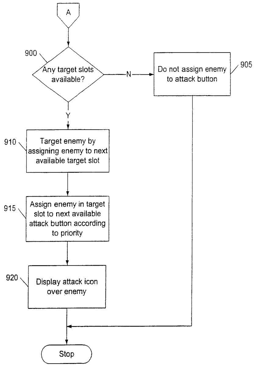
As discussed above, the flow diagram shown inFIG. 9describes the computer operations that are performed in the situation where at least one target slot is already filled and the user attempts to target an additional enemy. In the first operation, represented by the flow diagram box numbered900, the CPU300determines whether any target slots are available. A target slot is available if it is not already filled with an identifier code for an enemy character. If there are not any target slots available, this indicates that all target slots have already been filled with enemies.
If this is the case, the CPU300then proceeds to the next operation, represented by the flow diagram box numbered905. In this operation, the enemy920ais not assigned to a target slot. Rather, the game player must wait until a target slot is free before another enemy can be targeted. Preferably, there are several ways that an assigned target slot can be freed for reassignment. One way is for the enemy character to be killed, such as a result of an attack by the player character415. A target slot may also be freed if the enemy character moves a predetermined distance away from the player character. If a group of enemy characters are assigned to one target slot, then the CPU300must removed all the enemy characters in the group from the target slot before the target slot is classified as free. Thus, all of the enemy characters would have to be killed or moved away from the player character the predetermined distance. When all enemy characters420have been removed from a target slot, then the target slot and the associated controller button are free for reassignment.
If the CPU300determines that there are indeed target slots available, then the CPU300proceeds to the next operation, represented by the flow diagram box numbered910. In this operation, the CPU300targets the enemy character by assigning the enemy character to the next available target slot. This is described with reference toFIG. 10.FIG. 10shows that a second enemy character420bhas intersected the target range indicator440. Furthermore, at least one other enemy character, enemy character420a,has already been targeted, as indicated by the attack icon710aover the enemy character420a.In this example, the CPU300would assign the enemy character420bto the next available target slot.
With reference again toFIG. 9, in the next operation, represented by the flow diagram box numbered915, the CPU300associates the targeted enemy(s) in the recently-filled target slot with one of the controller buttons250,255,260, or265according to the aforementioned priority order. In the example shown inFIG. 10, only the first controller button250has been associated with an enemy and controller buttons255,260, and265are free. The second controller button255is thus the next available controller button in the priority order. Thus, the CPU300associates the targeted enemy character420bwith the second controller button255. If the second controller button255had already been associated with an enemy character420, then the CPU300would have associated the enemy character420bwith the next available controller button in the priority order.
In the next operation, represented by the flow diagram box numbered920, the CPU300causes an attack icon710bassociated with the second controller button255to be displayed over the targeted enemy character420b.In the case shown inFIG. 10, the second controller button255was associated with the targeted enemy character420b.The second controller button255has a circle for an identifier symbol. Thus, the attack icon710bis in the shape of a circle. The operation then ends.
FIG. 11shows a flow diagram that illustrates the computer operations by which the game player may cause the player character to attack a target enemy. The process is further described with respect toFIG. 12, where there is illustrated a player character415and several enemy characters420, including two targeted enemy characters420aand420bthat are associated with the first controller button250and the fourth controller button265, respectively.
In the first operation, represented by the flow diagram box numbered1105, the CPU300detects that the game player actuates an input interface that is associated with a targeted enemy420. For example, with respect toFIG. 12, the game player could press either the first controller button250, which is associated with the targeted enemy character420a,or the fourth controller button265, which is associated with the targeted enemy character420b.
In the next operation, represented by flow decision box numbered1110, the CPU300determines whether the targeted enemy is in range for attack. As mentioned, the player character420uses weapons, weapons that each have a particular attack capability, including an attack range. If the targeted enemy character is not within the player character's attack range, the CPU300causes the player character to face the targeted enemy character without initiating an attack. This operation is represented by the flow diagram box numbered1115. In the example shown inFIG. 12, this would correspond to the game player pressing the first controller button250, which is associated with the targeted enemy character420a.The front face indicator430points toward the enemy character420a,indicating that the player character415is facing the enemy character420a.The enemy character420ais presumed to be out of the player character's attack range.
However, if a targeted enemy character is within range, then pressing of the controller button associated with the targeted enemy character causes the player character to attack the targeted enemy character. This is represented by the flow diagram box numbered1120inFIG. 11. With reference toFIG. 12, this would correspond to the game player pressing the fourth controller button265, which is associated with the targeted enemy character420b.If the game player presses the fourth controller button, then the player character415will initiate an attack on the enemy character420b.The enemy character420bis assumed to be within the player character's attack range.
Advantageously, the player character does not need to be facing an enemy character in order to attack an enemy character. Preferably, the player character can initiate attacks on enemy characters even when not facing the enemy character. For example, the player character could initiate a behind-the-back sword swing on an enemy character located behind the player character, or a sideways swing on an enemy character to the side. In such a case, the CPU300would initiate an animation wherein the player character attacks the enemy character while not facing the enemy character. This advantageously increases the number of available attack moves, which increases enjoyability of the game. It also makes it easier for a game player to attack specific enemy characters. The game player can cause the player character to attack any targeted enemy character by simply pressing the controller button associated with the target, regardless of whether the player character is actually facing the enemy character. Preferably, after the first attack is initiated on an enemy character, the CPU300causes the player character to turn and face the enemy character, as represented by the flow diagram box numbered1115.
The game player can preferably cause the player character to initiate special attacks by pressing a combination of buttons on the controller. In one embodiment, the game player uses the unassigned controller buttons, if any, to initiate special attacks. For example, inFIG. 12, the second and third controller buttons255,260are not associated with any targets. If the game player presses one of the unassigned buttons immediately after pressing an assigned controller button, then the CPU300causes the player character to initiate a special attack on the targeted enemy character. A special attack could comprise a combination of attack moves or one or more unique attack moves. For example, a particular player character could have a special signature move that is unique to the player character, such as a unique swing or flourish move.
If the game player presses a controller button that is associated with a group of player characters, then the player character preferably attempts to attack as many of the enemy characters in the group as possible. For example, if the player character is using a taiaha, then the player character attempts to attack the maximum number of enemy characters that can be attacked with a taiaha. The game player can maneuver the player character into a location that will maximize the attack range.
In addition to providing an indication of the associated controller button, the attack icon710(FIG. 7) preferably provides status indications to the game player. The CPU300preferably causes the attack icon for an enemy to change visual state in response to the status of an enemy character. Preferably, an enemy character's attack icon710is in a first visual state, such as in a brightened state, when the enemy character is in range to be attacked by the player character. The attack icon710changes to a second visual state, such as a semitransparent state, if the associated enemy target is out of range of attack for the player character. The attack icon could also change to a third visual state, such as a flashing state, when the associated enemy target is close enough to be hit but will be missed if attacked. In one embodiment, the attack icon changes to the flashing state to indicate that the enemy is about to be de-targeted, such as when the enemy character is about to die or if the enemy character is about to move out of attack range.
FIG. 13is a block diagram that shows an exemplary software structure for implementing the game program described herein. A virtual environment data base1305stores data that describes the virtual environment. The virtual environment could be a finite, two-dimensional space that is managed as an X-Y coordinate system. Thus, any position in the virtual environment can be specified in the form of coordinates (x,y). The virtual environment could be divided into one or more blocks, wherein each block has a set of attributes that describe a portion of the virtual environment. The attributes could determine geographical information of the virtual environment and could comprise code for expressing a road, a river, a hill, a forest, etc. The blocks could also include image data for creating an image associated with the block.
The software structure also includes an image forming module1310that communicates with the virtual environment database1305. The image forming module1310provides position and color information for the GPU.
An operation receiving module1315communicates with the controller120. The operation receiving module1315accepts signals from the controller120regarding the states of the input interfaces on the controller120. The operation receiving module1315determines an action of the player character in accordance with the game player actuating the controller120. The operation receiving module1315determines movement direction of the player character through the virtual environment and also determines when the player character should initiate attacks. The movement directions of the joysticks270are preferably made to correspond to corresponding movements of the player character. The operation receiving module1315preferably also determines when the target range indicator440should be displayed in response to actuation of an input interface on the controller120.
A player position calculation module1320performs a process for calculating the position and movement of the player character in the virtual environment. In response to signals from the operation receiving module1315, the player position calculation module1325periodically calculates the position of the player character with respect to a previous position in the virtual environment. The player position calculation module1315then determines a movement direction for the player character.
A display control module1330accepts image information, such as position and color information, from the image forming module1310and the player position calculation module1320and then forwards rendering instructions to the GPU for processing.
The software structure also includes an enemy control module1335that maintains the position of each enemy character. The enemy control module1335also controls movement of the enemy characters through the virtual environment.
The present invention has been described above in terms of a presently preferred embodiment so that an understanding of the present invention can be conveyed. There are, however, many configurations for entertainment systems not specifically described herein but with which the present invention is applicable. The present invention should therefore not be seen as limited to the particular embodiments described herein, but rather, it should be understood that the present invention has wide applicability with respect to entertainment systems and video games generally. All modifications, variations, or equivalent arrangements and implementations that are within the scope of the attached claims should therefore be considered within the scope of the invention.
Claims
- A method for causing a player object to target and attack one or more enemy objects in a virtual environment, comprising: displaying a target range indicator that defines the target range of the player object, the target range indicator comprising a bounded area that encompasses a region of a display screen;maneuvering the target range indicator toward a first enemy object so that the first enemy object is at least partially located within the region of the display screen that is encompassed by the bounded area of the target range indicator;associating the first enemy object with a first button on an input device according to a button hierarchy, the button hierarchy prioritizing plural buttons on the input device in a predetermined priority order wherein the first button is the first button in the priority order;maneuvering the target range indicator toward a second enemy object so that the second enemy object is at least partially located within the region of the display screen that is encompassed by the bounded area of the target range indicator;associating the second enemy object with a second button on the input device according to the button hierarchy, wherein the second button is the next button in the priority order after the first button;and causing the player object to attack an enemy object when the button associated with the enemy object is pressed.
- The method of claim 1 , further comprising displaying the player object on the display screen.
- The method of claim 2 , wherein the target range indicator extends radially outward from the player object on the display screen.
- The method of claim 1 , further comprising displaying an attack icon over an enemy object when the enemy object is associated with a controller button, the attack icon comprising a symbol that identifies the associated controller button.
- The method of claim 1 , further comprising causing the player object to attack an enemy object when the button associated with the enemy object is pressed regardless of whether the player object is facing the enemy object being attacked, wherein the player object faces a particular direction.
- The method of claim 1 , further comprising equipping the player object with a weapon, wherein the size of the region of the display screen encompassed by the bounded area of the target range indicator is dependent on the weapon.
- The method of claim 1 , wherein the target range indicator is displayed in response to moving a joystick on the input device in a first direction and wherein the target range indicator extends in a direction that corresponds to the first direction that the joystick was moved.
- A machine-readable medium having embodied thereon a program, the program being executable by a machine to provide a method for causing a player object to target and attack one or more enemy objects in a virtual environment, the method comprising: displaying a target range indicator that defines the target range of the player object, the target range indicator comprising a bounded area that encompasses a region of a display screen;maneuvering the target range indicator toward a first enemy object so that the first enemy object is at least partially located within the region of the display screen that is encompassed by the bounded area of the target range indicator;associating the first enemy object with a first button on an input device according to a button hierarchy, the button hierarchy prioritizing plural buttons on the input device in a predetermined priority order wherein the first button is the first button in the priority order;maneuvering the target range indicator toward a second enemy object so that the second enemy object is at least partially located within the region of the display screen that is encompassed by the bounded area of the target range indicator;and associating the second enemy object with a second button on the input device according to the button hierarchy, wherein the second button is the next button in the priority order after the first button;and causing the player object to attack an enemy object when the button associated with the enemy object is pressed.
- The machine-readable medium of claim 8 , wherein the method further comprising displaying the player object on the display screen.
- The machine-readable medium of claim 9 , wherein the target range indicator extends radially outward from the player object on the display screen.
- The machine-readable medium of claim 8 , the method further comprising displaying an attack icon over an enemy object when the enemy object is associated with a controller button, the attack icon comprising a symbol that identifies the associated controller button.
- The machine-readable medium of claim 8 , the method further comprising causing the player object to attack an enemy object when the button associated with the enemy object is pressed regardless of whether the player object is facing the enemy object being attacked, wherein the player object faces a particular direction.
- The machine-readable medium of claim 8 , the method further equipping the player object with a weapon, wherein the size of the region of the display screen encompassed by the bounded area of the target range indicator is dependent on the weapon.
- The machine-readable medium of claim 8 , wherein the target range indicator is displayed in response to moving a joystick on the input device in a first direction and wherein the target range indicator extends in a direction that corresponds to the first direction that the joystick was moved.
- A system for targeting one or more enemy objects for attack with respect to a player object in a virtual environment, comprising: means for displaying a target range indicator that defines the target range of the player object, the target range indicator comprising a bounded area that encompasses a region of a display screen;means for maneuvering the target range indicator toward a first enemy object so that the first enemy object is at least partially located within the region of the display screen that is encompassed by the bounded area of the target range indicator;means for associating the first enemy object with a first button on an input device according to a button hierarchy, the button hierarchy prioritizing plural buttons on the input device in a predetermined priority order wherein the first button is the first button in the priority order;means for maneuvering the target range indicator toward a second enemy object so that the second enemy object is at least partially located within the region of the display screen that is encompassed by the bounded area of the target range indicator;means for associating the second enemy object with a second button on the input device according to the button hierarchy, wherein the second button is the next button in the priority order after the first button;means for causing the player object to attack an enemy object when the button associated with the enemy object is pressed.
- The system of claim 15 , further comprising means for displaying the player object on the display screen.
- The system of claim 16 , wherein the target range indicator extends radially outward from the player object on the display screen.
- The system of claim 15 , further comprising means for displaying an attack icon over an enemy object when the enemy object is associated with a controller button, the attack icon comprising a symbol that identifies the associated controller button.
- The system of claim 15 , further comprising means for causing the player object to attack an enemy object when the button associated with the enemy object is pressed regardless of whether the player object is facing the enemy object being attacked, wherein the player object faces a particular direction.
- The system of claim 15 , further comprising means for equipping the player object with a weapon, wherein the size of the region of the display screen encompassed by the bounded area of the target range indicator is dependent on the weapon.
- The system of claim 15 , wherein the target range indicator is displayed in response to moving a joystick on the input device in a first direction and wherein the target range indicator extends in a direction that corresponds to the first direction that the joystick was moved.
Disclaimer: Data collected from the USPTO and may be malformed, incomplete, and/or otherwise inaccurate.