U.S. Pat. No. 7,454,715
OPEN GRID NAVIGATIONAL SYSTEM
AssigneeMicrosoft Corporation
Issue DateFebruary 4, 2003

Summary:
The ‘715 patent describes a game system which helps a player navigate an open grid within a game or virtual environment. The invention calls for an indicated to be displayed which indicated a straight line direction between the current location of the player and the next unattained goal. Whenever a player nears a goal a symbol or indicator will appear on the screen to inform him of his nearness to the next goal. This invention has been used most frequently in car games like Crazy Taxi where completing goals is a vital part of the game. In that game, the character had a giant arrow above the car which directed him toward the next goal. This is an essential part of the game because it helps keep the player from getting lost and wandering around aimlessly.
Abstract:
To assist a player in navigating an open grid within a game or virtual environment, a global indicator and a local indicator are displayed within the virtual environment. The global indicator continuously indicates a straight line direction between an object controlled by the player and a next goal unattained within the virtual environment. As the object approaches within a predefined distance from a turn that should be taken to reach the next unattained goal, a local indicator is displayed showing the direction that the object should be turned to reach the goal. The local indicator is removed from the display after a predefined time has elapsed. Preferably, the local indicator is not displayed before a turn so long as continuing to move the object along a current path without turning at the next turn will permit the object to reach the next unattained goal.
Illustrative Claim:
1. A method for providing assistance to a user in navigating an object to a user in navigating an object to one or more unattained goals during a game in an open grid type virtual environment, comprising the steps of: maintaining a listing of one or more unattained goals within a virtual environment for which an object is to be navigated to by a user during a game; removing any unattained goal reached by the object during game play and that is included within the listing of the one or more unattained goals once it has been determined that the object has reached the unattained goal and such that the listing of the one or more unattained goals only includes unattained goals that still remain to be reached by the object during the game; identifying a next listed unattained goal within the listing that still remains to be reached by the object during the game; repeatedly displaying a global indicator that points in a direction directly from the object toward the next listed unattained goal within the virtual environment upon determining that the next listed unattained goal is present and until the next listed unattained goal is reached by the object and removed from the listing, and by at least iteratively performing the following: identifying a current location of the next listed unattained goal within the virtual environment; identifying a current location of the object within the virtual environment; and displaying the global indicator to point in a direction directly from the object toward the next listed unattained goal within the virtual environment, and such that the global indicator is repeatedly displayed from a time in which the next listed unattained goal is determined to be present and until the next listed unattained goal is reached by the object and removed from the listing, and such that each repeated display of the global indicator points in a direction directly from the object toward the next listed unattained goal and so as to dynamically reflect change in the current location of the object as the object is navigated within the virtual environment; providing a local indicator, which is graphically distinguished from the global indicator, and that generally points to indicate a direction of a specific turn to be taken by the object in the virtual environment-for reaching the goal; and displaying the local indicator in the virtual environment at least before the specific turn can be taken by the object to reach the goal, and wherein the local indicator is displayed simultaneously with the global indicator, at least temporarily.
Illustrative Figure
Abstract
To assist a player in navigating an open grid within a game or virtual environment, a global indicator and a local indicator are displayed within the virtual environment. The global indicator continuously indicates a straight line direction between an object controlled by the player and a next goal unattained within the virtual environment. As the object approaches within a predefined distance from a turn that should be taken to reach the next unattained goal, a local indicator is displayed showing the direction that the object should be turned to reach the goal. The local indicator is removed from the display after a predefined time has elapsed. Preferably, the local indicator is not displayed before a turn so long as continuing to move the object along a current path without turning at the next turn will permit the object to reach the next unattained goal.
Description
DESCRIPTION OF THE PREFERRED EMBODIMENT PC for Implementing the Present Invention With reference toFIG. 1, an exemplary general purpose computing device useful for implementing the present invention is illustrated in the form of a conventional PC20. While the present invention was initially developed for use on an electronic game playing system, it will be understood that the invention is generally applicable to almost any type of computing device that might be used to play electronic games or display navigate through a virtual environment, including, for example, mobile computers, hand held computing devices such as personal data assistants (PDAs), mobile communication devices (e.g., cell phones), and other computing devices that include a display on which a virtual environment is represented and which provide for controlling an object as it navigates an open grid to reach a goal. An embodiment of the present invention is readily implemented on a general purpose computing device such as represented by PC20. PC20is provided with a processing unit21, a system memory22, and a system bus23. The system bus couples various system components, including the system memory, to processing unit21and may be any of several types of bus structures, including a memory bus or memory controller, a peripheral bus, and a local bus using any of a variety of bus architectures. The system memory includes read only memory (ROM)24and random access memory (RAM)25. A basic input/output system26(BIOS), containing the basic routines that help to transfer information between elements within the PC20, such as during start up, is stored in ROM24. PC20further includes a hard disk drive27for reading from and writing to a hard disk (not shown) and may include a magnetic disk drive28for reading from or writing to a removable magnetic disk29, and an optical disk drive30for reading from or writing to a removable optical disk31, such ...
DESCRIPTION OF THE PREFERRED EMBODIMENT
PC for Implementing the Present Invention
With reference toFIG. 1, an exemplary general purpose computing device useful for implementing the present invention is illustrated in the form of a conventional PC20. While the present invention was initially developed for use on an electronic game playing system, it will be understood that the invention is generally applicable to almost any type of computing device that might be used to play electronic games or display navigate through a virtual environment, including, for example, mobile computers, hand held computing devices such as personal data assistants (PDAs), mobile communication devices (e.g., cell phones), and other computing devices that include a display on which a virtual environment is represented and which provide for controlling an object as it navigates an open grid to reach a goal.
An embodiment of the present invention is readily implemented on a general purpose computing device such as represented by PC20. PC20is provided with a processing unit21, a system memory22, and a system bus23. The system bus couples various system components, including the system memory, to processing unit21and may be any of several types of bus structures, including a memory bus or memory controller, a peripheral bus, and a local bus using any of a variety of bus architectures. The system memory includes read only memory (ROM)24and random access memory (RAM)25. A basic input/output system26(BIOS), containing the basic routines that help to transfer information between elements within the PC20, such as during start up, is stored in ROM24. PC20further includes a hard disk drive27for reading from and writing to a hard disk (not shown) and may include a magnetic disk drive28for reading from or writing to a removable magnetic disk29, and an optical disk drive30for reading from or writing to a removable optical disk31, such as a CD-ROM or other optical media, all of which comprise non-volatile memory media. Hard disk drive27, magnetic disk drive28, and optical disk drive30are connected to system bus23by a hard disk drive interface32, a magnetic disk drive interface33, and an optical disk drive interface34, respectively. The drives and their associated computer readable media provide nonvolatile storage of computer readable machine instructions, data structures, program modules, and other data for PC20. Although the exemplary environment described herein includes a hard disk, removable magnetic disk29, and removable optical disk31, it will be appreciated by those skilled in the art that other types of computer readable media, which can store data that are accessible by a computer, such as magnetic cassettes, flash memory cards, DVDs, Bernoulli cartridges, RAMs, ROMs, and the like, may also be used in the exemplary operating environment.
A number of program modules may be stored on the hard disk, magnetic disk29, optical disk31, ROM24or RAM25, including an operating system35, one or more application programs36, other program modules37, and program data38. A user may enter commands and information into PC20through input devices such as a keyboard40and a pointing device42. Pointing device42may include a mouse, stylus, wireless remote control, or other pointer. Other input devices (not shown) may include a joystick, game pad, wheel, pedal, microphone, satellite dish, scanner, digital camera, digital video recorder, or the like. These and other input/output (I/O) devices are often connected to processing unit21through an I/O interface46that is coupled to the system bus23. The term I/O interface is intended to encompass each interface specifically used for a serial port, a parallel port, a game port, a keyboard port, and/or a universal serial bus (USB). A monitor47or other type of display device is also connected to system bus23via an appropriate interface, such as a video adapter48, and is usable to display application programs, Web pages, a simulated or virtual environment such as in the present invention, and/or other information, including visual content of a digital media work that is being played from its original distribution medium, such as a CD-ROM, DVD, or other storage medium. In addition to the monitor, PCs are often coupled to other peripheral output devices (not shown), such as speakers55(through a sound card or other audio interface (not shown)), and printers (also not shown).
As indicated above, the invention may be developed and practiced on a single computing device; however, PC20may operate in a networked environment using logical connections to one or more remote computers, such as a remote computer49. Remote computer49may be another PC, a server (which is typically generally configured much like PC20), a router, a network PC, a game console, a peer device, a satellite, or other common network node. Remote computer49may include many or all of the elements described above in connection with PC20. So as not to makeFIG. 1unnecessarily complex, remote computer49is shown with only an external memory storage device50. The logical connections depicted inFIG. 1include a local area network (LAN)51and a wide area network (WAN)52. Such networking environments are common in offices, enterprise wide computer networks, intranets, and the Internet. When coupled to the Internet, electronic games or other applications in which a virtual environment is employed can be loaded and executed, permitting for example, play of an electronic game or interaction in a virtual environment with other PCs over the network.
When used in a LAN networking environment, PC20is typically connected to LAN51through a network interface or adapter53, which may be a wireless network adapter. When used in a WAN networking environment, PC20typically includes a modem54, or other means such as a cable modem, Digital Subscriber Line (DSL) interface, or an Integrated Service Digital Network (ISDN) interface, for establishing communications over WAN52. One type of WAN commonly used for communication is the Internet. Modem54, which may be internal or external, is connected to the system bus23or coupled to the bus via I/O device interface46, i.e., through a serial port. In a networked environment, program modules depicted relative to PC20, or portions thereof, may be stored in the remote memory storage device. It will be appreciated that the network connections shown are exemplary and other means of establishing a communications link between the computers may be used, such as wireless communication and wide band network links.
Electronic Gaming Console Environment
As shown inFIG. 2, an exemplary electronic gaming system100that is suitable for practicing the present invention includes a game console102and support for up to four user input devices, such as controllers104aand104b. Game console102is equipped with an internal hard disk drive (not shown in this Figure), which provides non-volatile storage, and a portable media drive106that supports various forms of portable optical storage media, as represented by an optical storage disk108. Examples of suitable portable storage media include DVD discs and CD-ROM discs. In this gaming system, game programs are preferably distributed for use with the game console on DVD discs, but it is also contemplated that other storage media might instead be used on this or other types of systems that employ the present invention.
On a front face of game console102are four slots110for connection to supported controllers, although the number and arrangement of the slots may be modified. A power button112and an eject button114are also positioned on the front face of game console102. Power button112controls application of electrical power to the game console, and eject button114alternately opens and closes a tray (not shown) of portable media drive106to enable insertion and extraction of storage disk108, so that the digital data on it can be read for use by the game console.
Game console102connects to a television or other display monitor or screen121via audio/visual (A/V) interface cables120. A power cable plug122conveys electrical power to the game console when connected to a conventional alternating current line source (not shown). Game console102includes an Ethernet data connector124to transfer and receive data over a network (such as through a connection to a hub or a switch (not shown)), or over the Internet, for example, through a connection to an xDSL interface, a cable modem, or other broadband interface (not shown). Other types of game consoles that implement the present invention may be coupled together or to a remote server, by communicating using a conventional telephone modem, but the ability to connect to another computer or game console is not particularly relevant to the present invention.
Each controller104aand104bis coupled to game console102via a lead (or alternatively through a wireless interface). In the illustrated implementation, the controllers are USB compatible and are connected to game console102via USB cables130; however, it is contemplated that other types of data interfaces may instead be employed. Game console102may be equipped with any of a wide variety of user devices for interacting with and controlling the game software. As illustrated inFIG. 2, each controller104aand104bis equipped with two thumbsticks132aand132b, a D-pad134, buttons136, and two triggers138. These controllers are merely representative, and other gaming input and control devices may be substituted for or added to those shown inFIG. 1for use with game console102.
A removable function unit140can optionally be inserted into each controller104aand104bto provide additional features and functions. For example, a portable memory unit (MU) enables users to store game parameters and port them for play on other game consoles, by inserting the portable MU into a controller connected to the other game console. Another removable functional unit comprises a voice communication unit that enables a user to verbally communicate with other users locally and/or over a network. Connected to the voice communication unit is a headset142, which includes a boom microphone144. The circuitry of the voice communication unit may alternatively be integrated into the controller and another headset with boom microphone, may be removably or permanently connected to the controller. Preferably, each controller is configured to accommodate two removable function units, although more or fewer than two removable function units or modules may instead be employed.
Gaming system100is capable of playing a variety of types of digital media works, including, for example, music and videos. It is contemplated that other functions can be implemented using digital data stored on the hard disk drive or read from optical storage disk108in drive106, or using digital media works obtained from an online source, or from a MU. For example, gaming system100is potentially capable of playing:Digital music stored on a CD in portable media drive106, in a file on the hard disk drive (e.g., WINDOWS MEDIA AUDIO™ (WMA) format), or derived from online streaming sources on the Internet or other network; andDigital A/V data stored on a DVD disc in portable media drive106, or in a file on the hard disk drive (e.g., after the media work has been copied and converted to an Active Streaming Format), or from online streaming sources on the Internet or other network.
Exemplary Virtual Environment Showing Use of Present Invention
FIGS. 3,4, and5illustrate how the present invention is applied within an electronic game in which players attempt to control an automobile to navigate the streets of a virtual environment to reach a succession of checkpoints. The player that reaches all of the checkpoints in the shortest time is the winner in this simple game. Generally, the streets in the game along which the vehicles controlled by the players move, are laid out in an open grid in which the streets intersect at about 90 degrees.FIG. 3illustrates an exemplary simplified display200within such a game. As shown in this Figure, a vehicle202is controlled by a player using a game pad, joystick, or other appropriate user input device, such as those discussed above in regard to PC20and game console100ofFIGS. 1 and 2, respectively. Although not constrained to remain on a street204inFIG. 3, vehicle202is preferably controlled to drive along street204, when heading toward the next checkpoint or goal, avoiding other objects such as vehicles206and208. In a game, it is likely that landscaping and other types of objects might be included along the sides of the streets, to encourage the player to drive the vehicle only on the open grid. To assist the player controlling vehicle202, a global indicator210is provided on display200and appears generally as a compass arrow showing the straight line direction between vehicle202and the next checkpoint in a succession of checkpoints that the player much reach during game play. The direction to the next checkpoint indicated by global indicator210is independent of the open grid defined by streets such as street204along which vehicle202is preferably moving in the virtual environment.
It should be noted that the player controlling vehicle202may be free to take various routes to reach the next checkpoint, and given only the direction indicated by global indicator210, will have some idea where to drive vehicle202within the constraints of the open grid. The player may also be provided with an overhead map (not included in the illustrated example) showing the general location of vehicle202in regard to the open grid, but the overhead map may have a limited scope, so that the player will not necessarily be able to plot a path along the open grid using the overhead map, to reach the next checkpoint. Using global indicator210, the player can control vehicle202without the overhead map, so that it continues along the streets of the open grid, generally in the direction indicated by global indicator210. However, as noted above under the Background of the Invention, use of only global indicator210will not always provide sufficient information to enable a player to follow the correct street and turn where necessary to reach the next checkpoint. In some cases, a player might take a turn that seems appropriate to reach the next checkpoint, as indicated only by the direction of global indicator210, and subsequently determine that the turn taken was a bad choice, because it leads to a dead end or to some other hazard or impassable barrier.
FIG. 4illustrates how the present invention displays a local indicator214in the virtual environment to assist the player in navigating through the open grid to reach the next checkpoint or goal. As shown inFIG. 4, the player has followed street204, which has led to an intersection216with a street212that extends at right angles to street204. The player controlling vehicle202will know that the vehicle should be turned right at intersection216onto street212, since local indicator214clearly shows that the turn should be made in that direction. Although not evident inFIG. 4, global indicator210will have been pointing generally toward the right (as shown inFIG. 3) for several intersections, but local indicator214will not be displayed until vehicle202is approaching intersection216. Because local indicator214is displayed, the player controlling vehicle202will understand that the vehicle should be turned to the right at intersection216and should not continue straight ahead on street204until another intersection is approached.
It should also be understood that the particular views illustrated inFIGS. 3 and 4are from an observation point that is behind the vehicle being controlled. However, the present invention is not limited to that viewpoint. It is contemplated that the player's viewpoint could instead be from the driver's seat inside vehicle202, for example, looking out through a front window of the vehicle. Other user or game selectable viewpoints are also contemplated in regard to the present invention. Accordingly, it is not intended that any limitation be implied by the manner in which the local indicator214and global indicator210are illustrated relative to vehicle202in these simple examples. Also, to reduce the complexity of the drawings, buildings, trees, shrubbery, signs, and other objects and elements of the game are not shown within the exemplary displays ofFIGS. 3 and 4.
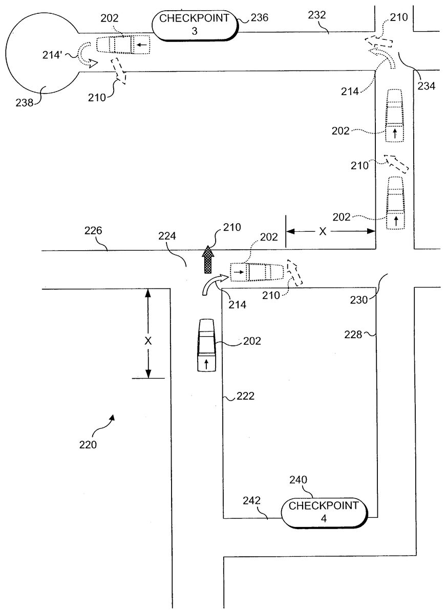
FIG. 5illustrates further details of the present invention by way of an example represented by an overhead view220. As shown inFIG. 5, vehicle202is currently traveling on a street222and is approaching a “T” intersection224, where street222meets a street226and does not continue any further. In this example, global indicator210is currently pointing in the same direction as vehicle202is currently traveling. Under this circumstance, based only on the information provided by the global indicator, a player would not know whether to turn left or right onto street226at intersection224. However, the present invention displays local indicator214in the virtual environment, so that the player can be alerted that vehicle202should make a right turn onto street226from street222. This example makes clear the benefit of providing both global indicator210and local indicator214on the display, so that the person controlling an object such as vehicle202will know when to make a turn and in which direction to turn to reach a goal such as a checkpoint236(i.e., “CHECKPOINT 3”). Without local indicator214it would not be apparent that the vehicle should be turned right at intersection224. Indeed, it is possible that if the player were to turn vehicle202toward the left, with the expectation of being able to follow a different route to reach checkpoint236while traveling in that direction, the player might then find that street226reaches a dead end, or does not intersect with another street that would enable vehicle202to travel toward checkpoint236.
Another important aspect of the present invention is that local indicator214is not displayed to the user until vehicle202is within a predefined distance “X” from intersection224. By displaying local indicator214only within the predefined distance from an intersection at which a next turn is to be made, confusion is avoided in regard to where the player should control the vehicle to make a turn. In addition, the distance before the intersection at which the local indicator is first displayed is sufficient so that the player will have adequate time to slow vehicle202as necessary to negotiate the indicated turn. For this reason, it is also contemplated that the predefined distance before the intersection at which local indicator214is displayed can be varied as the speed of an object such as vehicle202varies within the virtual environment. It will be apparent that if vehicle202is traveling at a relatively faster rate, it will be necessary that the player be provided more advance warning of an upcoming turn, i.e., that the local indicator be displayed at a greater distance “X” before the next intersection at which the turn is to be made than would be required if the vehicle or other object were traveling at a slower speed.
Vehicle202is shown in dotted lines on street226after making the turn as indicated by local indicator214. When in this location on street226, global indicator210(now shown in dashed lines) appears in front of the vehicle on street226, indicating the straight line-of-sight or “as the crow flies” direction from the location of the vehicle at that point, to checkpoint236. Since immediately after making the right turn onto street226, vehicles202is not yet within the distance “X” from the next intersection where a turn will be required, a local indicator would not yet be displayed. However, as vehicle202approaches (within distance “X”) from an intersection230of street226and street228, local indicator214would be displayed, indicating that a turn is suggested to the left onto street228from street226. Vehicle202is shown in dotted lines right after making such a turn onto street228and again, as approaching an intersection234of street228with a street232. As the vehicle approaches intersection234, local indicator214will again be displayed to indicate that the player should turn the vehicle left onto street232, and global indicator210will be displayed, pointing toward checkpoint236.
After making the left turn onto street232the player controlling vehicle202will stop at checkpoint236or otherwise tag the goal to indicate that it has been reached. Since checkpoint236is identified as “CHECKPOINT 3,” the next successive checkpoint in a list of checkpoints yet to be reached will be a checkpoint240, which is identified as “CHECKPOINT 4.” After reaching checkpoint236, vehicle202must do a U-turn in a turnabout 238. To provide a navigational hint to the player controlling vehicle202, a local indicator214′ is displayed that indicates vehicle202should do a U-turn. In addition, global indicator210is displayed pointing toward checkpoint240. In this preferred embodiment of the present invention, local indicator214can only indicate a left turn, a right turn, or a U-turn. No attempt is made to indicate whether an object should veer left or veer right through less than a 90 degree turn. However, it will be apparent that the local indicator214could be provided for other turns of varying degree.
When traveling along street222to reach the position shown inFIG. 5, vehicle202might have been turned right onto a street242, if the player controlling the vehicle chose to do so. It must be emphasized that global indicator210and local indicator214are only provided as hints or suggestions for assisting the player in navigating the open grid of a virtual environment or game in which the present invention is used. If the player had chosen to turn right on street242, the player might also have stopped at checkpoint240(CHECKPOINT 4) before reaching checkpoint236(CHECKPOINT 3) even though checkpoint240is out of sequence. It will be understood that some games might require a player to reach the goals in a predefined order or sequence. However, in this particular application of the present invention, a player is permitted to achieve a goal by stopping at a checkpoint out of sequence, and once the checkpoint is thus reached, the player is not again required TO DRIVE the vehicle to reach the checkpoint, because the checkpoint is removed from the list of unattained checkpoints. Accordingly, once a player has reached a checkpoint or goal in the game, that fact is noted, and global indicator210and local indicator214will be displayed to direct the player to control the vehicle to each remaining unattained checkpoint in the sequence of checkpoints.
A further point should also be noted in regard to the use of a local indicator to provide a navigational aid to the player controlling vehicle202. As stated above, the player might have turned vehicle202right onto street242from street222and proceeded up street228after making a left turn from street242. Thus, the player could have followed an alternative path to reach checkpoint236other than that indicated by local indicator214at intersection224. However, the present invention does not display the local indicator to suggest that the object be turned at the next intersection, so long as continuing straight ahead will continue to enable a player to reach the next checkpoint or goal. For this reason, local indicator214is not displayed to indicate a right turn onto street242from street222, but instead is only displayed once vehicle202is approaching intersection224, where the vehicle must make a right turn in order to continue on toward checkpoint236.
Logic Applied in Implementing the Present Invention
A flowchart250inFIG. 6illustrates the steps implemented in displaying the global indicator in the present invention. From a start block252a decision step254determines if any goal is present within the virtual environment. Again, the virtual environment includes an open grid through which an object is being navigated by a user. If no goal is yet unattained, it is presumed that the user has reached all of the goals and the logic terminates. However, if any goal remains to be reached, the logic proceeds with a step256that locates the next unattained goal in the virtual environment. Depending on the nature of the virtual environment and its implementation, a coordinate system may be provided that defines the location of each goal within the virtual environment using game coordinates. However, other techniques can also be used for specifying the location of each goal in the virtual environment. Next, in a step258, the software locates the object that is being navigated through the open grid in the virtual environment, using the coordinate system or other appropriate technique, as noted above. Next, a step259displays the global indicator so that it points from the object directly toward the goal.
InFIG. 7, details of locating the next unattained goal in the virtual environment in step256are illustrated. From a start block260, a step262preferably provides for checking a list of unattained goals that are maintained in sequence. In this application of the present invention, the goals may be reached in any particular order, but unattained goals are nevertheless identified in an ordered list or some other form of data. As noted above, once a goal has been reached in the exemplary game, the goal is removed from the list of unattained goals. Accordingly, a step264returns a first unattained goal from the list of unattained goals. Next, a step266determines the relative location of the goal in the virtual environment, using the game coordinate system or some other appropriate technique. Control is then returned to step258inFIG. 6, as indicated by a block268.
A flow chart270inFIG. 8illustrates steps for maintaining the list of unattained goals. From a start block272, a decision block274determines if the player has controlled the object so that a goal has just been reached. If not, the logic continues looping until the player reaches a goal. Once a goal has been reached, a decision step276determines if the goal that has just been reached is in the unattained list of goals. If not, it is assumed that the player has previously reached this goal and that this goal need not be considered again, since it has already been removed from the list of goals. Accordingly, the logic returns to decision step274to await the player reaching another goal. However, if decision step276determines that the goal is in the list of unattained goals, a step278removes the goal from the unattained list. Next, a decision step280determines if any goals remain to be reached in the unattained list, and if not, a step282indicates that the game is over. If there are still unattained goals to be reached by the player, the logic returns to decision step274to await the player reaching another goal.
A flow chart300, which is shown inFIG. 9, illustrates the logical steps that are implemented in order to facilitate displaying the local indicator. From a start block302, a step304provides for locating the next unattained goal in the virtual environment. This step corresponds to the logical steps shown inFIG. 7. Next, a step306provides for locating the object in a virtual environment. In both steps306and304, the game coordinate system or other appropriate technique can be used for specifying the location of both the next unattained goal and the object that is being navigated through the open grid.
A decision step308next determines if the object is within a predefined distance from the goal. As noted above, it is contemplated that the predefined distance can be varied as a function of the speed of the object within the virtual environment. If this option is employed, an object traveling at a higher speed will result in the predefined distance being increased compared to the case when an object is traveling at a slower speed. If the object is not within the predefined distance from the goal, the logic continues with a decision step309, which determines if the local indicator is currently being displayed. If so, since the object is not within the predefined distance from the goal, a step311provides for removing the local indicator from the display. The logic then continues back to step306. Similarly, if the local indicator is not currently being displayed in decision step309, the logic also simply returns to step306.
If the result in decision step308is affirmative, a step310locates the next recommended change in direction of the object in regard to the open grid of the virtual environment. In regard to the simple example shown inFIG. 5, step310would locate the next street that turns left or right relative to the current street on which the object is traveling. In addition, a recommended turn can also include a U-turn where a turnabout is disposed ahead on the current street being traveled by the object. After step310, a decision step312determines if continuing on the current path will lead the object to the next unattained goal. If so, the local indicator should not be displayed for the next recommend change in direction, and the logic advances to decision step309to determine if the local indicator is currently being displayed, and if so, step311removes the local indicator from the display. Conversely, if the local indicator is not currently being displayed, the logic loops back to step306. If continuing on the current path does not lead to the goal, a decision step314determines if the next suggested change in direction leads to the goal. If not, the logic returns to step306; however, if the response to decision step314is affirmative, a step316displays the local indicator. Next, a decision step318determines if the goal has been reached or otherwise accomplished. If the goal has not been accomplished, the logic again returns to step306. Once the goal has been accomplished, a step320removes the local indicator, and the logic loops back to step304.
Although the present invention has been described in connection with the preferred form of practicing it and modifications thereto, those of ordinary skill in the art will understand that many other modifications can be made to the present invention within the scope of the claims that follow. Accordingly, it is not intended that the scope of the invention in any way be limited by the above description, but instead be determined entirely by reference to the claims that follow.
Claims
- A method for providing assistance to a user in navigating an object to a user in navigating an object to one or more unattained goals during a game in an open grid type virtual environment, comprising the steps of: maintaining a listing of one or more unattained goals within a virtual environment for which an object is to be navigated to by a user during a game;removing any unattained goal reached by the object during game play and that is included within the listing of the one or more unattained goals once it has been determined that the object has reached the unattained goal and such that the listing of the one or more unattained goals only includes unattained goals that still remain to be reached by the object during the game;identifying a next listed unattained goal within the listing that still remains to be reached by the object during the game;repeatedly displaying a global indicator that points in a direction directly from the object toward the next listed unattained goal within the virtual environment upon determining that the next listed unattained goal is present and until the next listed unattained goal is reached by the object and removed from the listing, and by at least iteratively performing the following: identifying a current location of the next listed unattained goal within the virtual environment;identifying a current location of the object within the virtual environment;and displaying the global indicator to point in a direction directly from the object toward the next listed unattained goal within the virtual environment, and such that the global indicator is repeatedly displayed from a time in which the next listed unattained goal is determined to be present and until the next listed unattained goal is reached by the object and removed from the listing, and such that each repeated display of the global indicator points in a direction directly from the object toward the next listed unattained goal and so as to dynamically reflect change in the current location of the object as the object is navigated within the virtual environment;providing a local indicator, which is graphically distinguished from the global indicator, and that generally points to indicate a direction of a specific turn to be taken by the object in the virtual environment-for reaching the goal;and displaying the local indicator in the virtual environment at least before the specific turn can be taken by the object to reach the goal, and wherein the local indicator is displayed simultaneously with the global indicator, at least temporarily.
- The method of claim 1 , wherein the step of displaying the local indicator includes the step of enabling the display of the local indicator only when the object is within a predefined distance from the specific turn.
- The method of claim 2 , further comprising the step of varying the predefined distance as a function of a speed of the object within the virtual environment.
- The method of claim 3 , wherein the predefined distance is greater for a higher speed of the object than for a lower speed of the object.
- The method of claim 1 , wherein the goal is one of a plurality of goals that are to be reached by the object within the virtual environment, further comprising the steps of pointing the global indicator in the direction of a successive unattained goal included within the listing of one or more unattained goals that is yet to be reached by the object after the next unattained goal is reached and removed from the listing.
- The method of claim 5 , further comprising the step of displaying the local indicator so as to indicate successive turns that should be taken in the virtual environment to reach the successive unattained goal.
- The method of claim 5 , wherein the global indicator and the local indicator only respond to the location of a current goal in the virtual environment and wherein the next unattained goal is the current goal until being reached and after which the successive unattained goal becomes the current goal.
- The method of claim 5 , further comprising the step of deleting a particular unattained goal from the listing of the one or more unattained goals after the particular unattained goal is reached by the object and prior to deleting the next unattained goal from the listing.
- The method of claim 1 , wherein the method includes refraining from displaying the local indicator before a next turn that could be taken to reach the next unattained goal when it is determined that continuing on a current path without turning the object at the next turn will still enable the object to reach the next unattained goal in the virtual environment.
- The method of claim 1 , wherein the local indicator indicates one of a left turn, a right turn, and a U-turn.
- A memory medium storing machine instructions for carrying out the steps of claim 1 .
- The method recited in claim 1 , wherein the global indicator indicates a straight-line direction between the next unattained goal and the object.
- The method of claim 1 , further comprising the step of only displaying the local indicator at times in which it is determined that a current direction in which the object is traveling will not enable the object to reach the next unattained goal.
- The method of claim 1 , wherein the local indicator indicates an orthogonal turn relative to a present direction of travel.
- The method of claim 1 , wherein the local indicator indicates a U-turn.
- A system for providing assistance in controlling an object to reach a goal in an open grid of a virtual environment, comprising: (a) a display on which the virtual environment is visually apparent;(b) a memory in which machine instructions are stored;(c) a user control for providing input to control the object in the virtual environment;(d) a processor coupled to the display, the user control, and the memory, said processor executing the machine instructions which cause the processor to implement the method recited in claim 1 .
- The system of claim 16 , wherein the machine instructions further cause the processor to display the local indicator on the display only when the object is within a predefined distance from the specific turn.
- The system claim 17 , wherein the machine instructions further cause the processor to vary the predefined distance as a function of a speed of the object within the virtual environment.
- The system of claim 16 , wherein the next unattained goal is one of a plurality of unattained goals that are to be reached by the object within the virtual environment, and wherein the machine instructions further cause the processor to display the global indicator pointing in a direction of each of the unattained goa 1 s in the listing that is yet to be reached by the object in a successive order and until each of the unattained goals is reached.
- The system of claim 19 , wherein the machine instructions further cause the processor to display the local indicator on the display so as to indicate successive turns that should be taken in the virtual environment to reach a subsequent unattained goal that is yet to be reached by the object, and only after the next unattained goal is reached.
- The system of claim 19 , wherein the machine instructions further cause the processor to control the global indicator and the local indicator to only respond to the location of a current goal in the virtual environment and wherein the next unattained goal is the current goal until being reached and after which a successive unattained goal in the listing becomes the current goal.
- The system of claim 19 , wherein the machine instructions further cause the processor to delete a specific unattained goal from the listing of unattained goals after the specific unattained goal is reached by the object, and even if the specific unattained goal was not reached in a predefined order.
- The system of claim 16 , wherein the machine instructions further cause the local indicator not to be displayed before a next turn that could be taken to reach the next unattained goal, if continuing to move the object on a current path without turning will still enable the object to reach the next unattained goal in the virtual environment.
- The system of claim 16 , wherein the machine instructions further cause the processor to employ the local indicator to indicate a U-turn.
- The method recited in claim 1 , wherein the local indicator and the global indicator each point in a different direction while being displayed simultaneously.
- The method recited in claim 1 , wherein the global indicator includes an arrow head graphic and the local indicator includes a different arrow head graphic.
- The method of claim 26 , wherein the arrow head graphic of the global indicator is larger than the different arrow head graphic of the local indicator.
- The method recited in claim 1 , wherein the global indicator is displayed directly above the object within a display of the virtual environment.
- The method recited in claim 1 , wherein the local indicator is displayed directly above the object within a display of the virtual environment.
- The method recited in claim 1 , wherein the virtual environment includes one or more paths that lead from the object to the next unattained goal and wherein the global indicator is displayed independently of the one or more paths.
Disclaimer: Data collected from the USPTO and may be malformed, incomplete, and/or otherwise inaccurate.