U.S. Pat. No. 7,413,514
VIDEO GAME MACHINE WITH ROTATIONAL MECHANISM
AssigneeKabushiki Kaisha Sega Enterprises
Issue DateSeptember 21, 2005
Illustrative Figure
Abstract
The invention provides an image processing unit for a shooting game in which suitable images can be displayed according to a given situation, and in which more exciting and easy-to-manipulate images are displayed. Coordinate values for objects in three-dimensional virtual space are established on the basis of prerecorded object shape data, view point positions are established on the basis of distances x1 and x2 from predetermined objects defined in three-dimensional virtual space (for example, the positions are lower when the distance is shorter, and higher when the distance is longer), the coordinate values established as described above are received, and the coordinate values are converted to a visual field coordinate system as seen from the view points established in the manner described above.
Description
BEST MODE FOR CARRYING OUT THE INVENTION First Aspect of the Invention Embodiments of the present invention are described below with reference to the drawings.FIG. 1is a block diagram depicting a first embodiment of the game unit in present invention. This game unit is an arcade game type of gun shooting game unit, comprising the base elements of a game unit frame10, input device11, TV monitor13, and speakers14. Input devices11are shooting weapons such as pistols, machine guns, rifles, and shotguns, for shooting enemies appearing in the game (the following description is of pistols). The pistol11includes a photoreceptor element not shown in the figure for reading scanning spots (light spots of an electron beam) for the points of impact on the TV monitor13, and a trigger switch not shown in the figure which is actuated by operating the gun trigger. Scanning spot detection timing and trigger timing signals are sent by means of a connecting cord to an input and output interface106described below. The TV monitor13displays the situation unfolding in the game, although a projector may be used instead of a TV monitor. The game unit frame unit10has a CPU (central processing unit)101, and is equipped with ROM102, RAM103, a sound device104, input and output interface106, scroll data processor107, coprocessor (auxiliary processing unit)108, topographical data ROM109, geometrizer110, shape data ROM111, imaging device112, texture ROM113, texture map RAM114, frame buffer115, image synthesizer116, and D/A convertor117. The aforementioned ROM102serving as the recording medium in the present invention includes other storage means such as hard discs, cartridge type ROM, CD-ROM and various other well-known types of media, as well as communications media (the Internet and various personal computer communications networks). The CPU101is connected by bus lines to the ROM102for storing specific programs and the like, RAM103for storing data, sound device104, input and output interface106, ...
BEST MODE FOR CARRYING OUT THE INVENTION
First Aspect of the Invention
Embodiments of the present invention are described below with reference to the drawings.FIG. 1is a block diagram depicting a first embodiment of the game unit in present invention. This game unit is an arcade game type of gun shooting game unit, comprising the base elements of a game unit frame10, input device11, TV monitor13, and speakers14.
Input devices11are shooting weapons such as pistols, machine guns, rifles, and shotguns, for shooting enemies appearing in the game (the following description is of pistols). The pistol11includes a photoreceptor element not shown in the figure for reading scanning spots (light spots of an electron beam) for the points of impact on the TV monitor13, and a trigger switch not shown in the figure which is actuated by operating the gun trigger. Scanning spot detection timing and trigger timing signals are sent by means of a connecting cord to an input and output interface106described below. The TV monitor13displays the situation unfolding in the game, although a projector may be used instead of a TV monitor.
The game unit frame unit10has a CPU (central processing unit)101, and is equipped with ROM102, RAM103, a sound device104, input and output interface106, scroll data processor107, coprocessor (auxiliary processing unit)108, topographical data ROM109, geometrizer110, shape data ROM111, imaging device112, texture ROM113, texture map RAM114, frame buffer115, image synthesizer116, and D/A convertor117. The aforementioned ROM102serving as the recording medium in the present invention includes other storage means such as hard discs, cartridge type ROM, CD-ROM and various other well-known types of media, as well as communications media (the Internet and various personal computer communications networks).
The CPU101is connected by bus lines to the ROM102for storing specific programs and the like, RAM103for storing data, sound device104, input and output interface106, scroll data processor107, coprocessor108, and geometrizer110. The RAM103functions as a buffer, writing various commands (such as object display) to the geometrizer110, writing matrices during conversion matrix computations, and the like.
The input and output interface106is connected to the aforementioned input device11(pistol). Pistol firing, the location of hits, the number of rounds fired, and the like are determined based on the scanning spot detection signals from the pistol11, the trigger signals indicating that the pistol trigger has been pulled, the current coordinate (X,Y) positions of the scanning electron beam on the TV monitor, and the position of the target, after which the various corresponding flags are set up in the prescribed positions in RAM103.
The sound device104is connected by a power amplifier105to a speaker14, and the sound effect signals generated by the sound device104are electrically amplified and given to the speaker14.
In the present embodiment, the CPU101reads the development of the game storyline on the basis of the program stored in ROM102, topographical data from ROM109, and shape data from the shape data ROM11(three-dimensional data such as “enemy characters and other such objects” and “scenery, buildings, interiors, subterranean passages and other such game backgrounds”) to simulate three-dimensional virtual space, to process shooting in response to trigger signals from the input device11, and the like.
The coordinate values in three-dimensional space for the various objects in virtual game space are established, and a conversion matrix for converting the coordinate values to a visual field coordinate system and shape data (buildings, terrain, interiors, laboratories, furniture, and the like) are designated by the geometrizer110. The topographical data ROM109is connected to the coprocessor108, and predetermined topographical data such as the path along which the camera moves are accordingly transferred to the coprocessor108(and CPU101). The coprocessor108determines direct hits, controls and computes deviation between the camera line of vision and object as well as the movement of the line of sight, and the like, and thus primarily computes fluctuating decimal points. The coprocessor108thus determines hits on objects and computes the position to which the line of vision is moved relative to the layout of objects, and the results are given to the CPU101. The well-known technique in Japanese Laid-Open Patent Application 8-36651, for example, can be used as the algorithm for determining hits.
The geometrizer110is connected to the shape data ROM111and imaging device112. Polygon shape data (three-dimensional data consisting of each apex, such as buildings, walls, corridors, interiors, terrain, background, protagonist, allies, and various types of enemies) are stored in the shape data ROM111, and the shape data are transferred to the geometrizer110. The geometrizer110sees through and converts shape data designated by a conversion matrix sent from the CPU101, and the converted data are provided to a visual field coordinate system based on a coordinate system in three-dimensional virtual space.
The imaging device112applies texture to the shape data of the converted visual field coordinate system for output to the frame buffer115. In order to apply the texture, the imaging device112is connected to the texture data ROM113and texture map RAM114, as well as to the frame buffer115. The polygon data are referred to as data groups of relative or absolute coordinates of each apex of polygons (polygons: primarily triangles or quadrangles) consisting of collections of a plurality of apices. The aforementioned topographical data ROM109houses relatively crudely established polygon data by which the camera moves through virtual space according to the game storyline. By contrast, the shape data ROM111houses more precisely established polygon data for the shapes constituting the screen for enemies, background, and the like.
The scroll data processor107computes scrolling data such as text, and this processor107and the aforementioned frame buffer115are connected by the image synthesizer116and D/A convertor117to the TV monitor13. By this means, temporarily stored objects (enemies), terrain (background), and other such polygon displays (simulation effects) as well as the scrolling display of other text data (such as a player's life count and damage points) are synthesized according to the designated priority to generate the final frame image data. The image data are converted by the D/A convertor117to analog signals, which are sent to the TV monitor13, and the shooting game images are displayed in real time.
The operations are described below.
Outline
The unit in the first embodiment of the present invention is used in a shooting game. For example, the player travels in a vehicle with a pistol as a weapon on the way to an appointed destination to rescue two missing parties while shooting enemies (such as dinosaurs) blocking the way. The game is played by one or two players who shoot at enemy individuals or groups. Combat between players and enemies is one-to-one or one against many.
When the player is traveling, an objective screen (screen displaying the surrounding environment including the player) is used. This is to show the surrounding environment to the player.
When an enemy appears, the screen is switched to subjective mode (screen seen from player's point of view), and the player engages the enemy.FIG. 2shows an example of the screen at this time. The player looks through the windshield out of the vehicle150(the front part of the vehicle is displayed on the screen) at the outside scene. The enemy (in this case, a dinosaur) jumps out of the shadows of a building153, and the player shoots at it with the gun11. Impact152is displayed in the location at which the gun is aimed when fired, and the discharge of a cartridge155is displayed. The plurality of cartridges154shows the number of bullets that can be fired.
When given conditions have been met (such as when all the enemies at that point have been killed or when sophisticated playing is achieved and the enemies escape), the player travels to the next point.
The game is over when a given number of stages has been met (arrival at the destination).
A gun sight (marker indicating the point at which the player should fire) is displayed on the enemy in the game screen, which may mean the following.
(1) Sight for Change in Storyline
With this sight, the storyline changes to the player's disadvantage (such as travel along a route in which many enemies appear) when no direct hits have been made in a specific period of time. This sight has a gage indicating the elapse of a specific period of time.FIG. 3depicts an example of the screen at this time. A circular site156appears around the enemy151.
(2) Sight for Appearance of Giant Dinosaur
This sight is displayed in a number of sites where a giant enemy dinosaur is found. The dinosaur is not killed except by a direct hit in all of the sights. This screen is described below.
Calculation of Back-Up Score
When the game is played by two players, the back-up score between partners is calculated by the following specific process.
As shown inFIG. 4, the screen201is divided into two equal portions to the left and right, and each player has an area sustaining damage from the enemy. The two divided screens are201A and201B, respectively. Player A is in charge of territory201A, and earns points by killing enemies appearing (displayed) in this territory201A. Player A also sustains damage from the enemies appearing in this territory201A. Player B is in charge of territory201B in the same manner as in the case of territory201A. Naturally, points are awarded according to the number of enemies killed and not according to territory.
FIG. 5shows the number and location of enemies killed (symbol202) by player A in a given period of time. Player A has killed seven enemies202in territory201A under his charge and three enemies in the other territory201B. That is, by killing three enemies in territory201B, player A has backed up player B.
Thus, as shown inFIG. 6, the enemies killed are divided according to territories201A and B, and the back-up score is defined as follows, where X=7 is the number of enemies202killed in territory201A, and Y=3 is the number of enemies203killed in territory201B.
Back-up score=(number of enemies killed by player in companion's territory)/(number of enemies killed in player's own territory)
=Y/(X+Y)
=3/10=30%
In this game, the back-up score is used as part of the score.
It is used, for example, to predict player compatibility on the final screen of the game. As shown inFIG. 7, the results such as the number of enemies killed by each player and hit ratio are displayed on the final screen, and the results of the compatibility diagnosis are also displayed. When the back-up score for two people is low on both sides (less than 50%), a message such as one saying “might be time to think about splitting up” is displayed, whereas when the back-up score for two people is high on both sides (about 70%), a message such as one saying “what a well-matched pair!” is displayed. When the back-up score is more than 50%, a message such as one saying “dependable” is displayed when 20>β>0, and a message such as one saying “good combo!” is displayed when 100>β>20, where β is the absolute value of the difference between back-up scores. This back-up score is also used as part of the score.
Moving Line of Vision
The line of vision moves vertically and horizontally depending on the game situation. This movement changes the sense of depth. For example, the line of vision is changed in stages as the enemy approaches, thereby displaying the approach by movement. As the enemy approaches, the path also widens, so as to keep the presence of the enemy as small as possible in the screen.
For example, as shown inFIG. 8, view points (camera positions)211aand211bare on the vehicle210on which the player is riding, and visual fields212aand212bare obtained, respectively, from these view points. When an enemy is in location213a(when the distance to the enemy is x1), the view point is211a. When the enemy is in location213b(when the distance to the enemy is x2), meanwhile, the view point is211b. The difference in height between view points211aand211bis h (view point211bis higher than view point211a). The height of the view point drops in proportion to the approach of the enemy, for example.
FIG. 9is a flow chart of this process. First, the view point is established at location211binFIG. 8, for example, for initialization (S1). It is determined whether or not the enemy location x2has changed (S2). When it has changed, the distance x1to the enemy is measured (S3). The camera position is then established at view point211ain conformity with the distance x1(S4).
Examples of screens are depicted inFIGS. 10 and 11.FIG. 10is of a screen when the enemy is at a distance, and is viewed from above. This screen allows a complete command of the scene, so that all enemies can be seen when several appear.FIG. 11is a screen of when the enemy is approaching, and allows the enemy to be apprehended from the front, making it easier to shoot.FIG. 11depicts a bullet directly hitting the enemy151.
The camera view point also moves so as to following the enemy that is closest to the player. When, for example, the closest enemy moves off screen, the line of sight is directed in the direction in which the enemy has moved. The closest enemy is thus always displayed in the screen. The player therefore knows which enemy is closest and should be killed, making it easier to know what to do.
When an enemy goes off screen, the line of vision automatically moves in the direction of the sound (roars and the like) made by the enemy. This allows the player to easily find new enemies.
Enemy Control (Part 1)
Enemies attack both individually and in groups. Enemies move between points P1through P5situated as shown inFIG. 12(based on spline function). Data are introduced at each point for the determination of branched/special motion and the like. For example, a given enemy follows the route from P1to P2to P3to P5, and another enemy follows the route from P1to P2to P4to P5. The points are arranged on or behind buildings, on or behind terrain, or the like. The manner in which these points are followed varies according to player level. The player can memorize these points to get through the game better.
Enemy Control (Part 2)
The behavior of an enemy is affected by other enemies. For example, when a given enemy cries out upon being attacked in a vulnerable spot, other enemies nearby stop and turn. When enemy movement thus halts, even for a moment, it is to the player's advantage.
Alternatively, when bullets directly hit glass or water, the enemy reacts to the sound of impact. For example, the enemies gather upon hearing such sounds. This allows an extremely realistic game to unfold.
The extent to which enemies are affected varies depending on the type and magnitude of the sound. For example, when the enemy leader is hit in a critical area (such as the crown of the head), all of the enemies may be affected. When glass is struck, enemies within a radius of 10 m in virtual space may be affected. Similarly, when a high-pitched metallic sound is produced, or an enemy other than the leader is struck on the crown of the head, or the sound of trees bursting is produced, enemies within a radius of 6, 3, or 2 m, respectively, may be affected.
Switching From Subjective Screen to Objective Screen
Until now, screens have been subjective, where the enemy is seen by the player. However, during multiple play, the screen is sometimes switched to an objective screen displaying a player on the screen. That is, the subjective screen is switched to an objective screen, allowing a player that is playing at the same time to help another player.
This is described with reference toFIGS. 13 and 14.FIG. 13(a) is of a screen in which the enemy151strikes and damages the vehicle in which the players are riding. The symbol157is an image indicating the impact. When the enemy151strikes the vehicle, one of the players is taken away. For example,FIG. 13(b) shows the player158on the right side of the vehicle just before being seized by the enemy. At this time, a damage point is added to the player.FIG. 13(a) is of a subjective screen, whereasFIG. 13(b) is of an objective screen.
FIG. 14shows the player being taken by the enemy (symbol158is the player). At this time, another damage point will be added to the player158unless the other player shoots the enemy's weak point (all of sight156inFIG. 14) within a prescribed period of time. Caution is required at this time since more player damage points will be added if the bullets strike the player158.
Gun Control
The ability to fire the gun11is demonstrated through control of the recoil and trigger. For example, when only one bullet shows up on the screen, the recoil is weak when the bullet can be fired. When no bullets are left, the trigger will not work.
Screen Selection
Either the score screen or objective screen can be selected for demonstration during the game. For example, as shown inFIG. 15, when a large objective screen221including objects221aand221band a small score screen222are displayed in the display screen220, the player strikes the selection screen223“SHOOT TO SCORE PAGE” to make the score screen222large and the objective screen211small, as shown inFIG. 16. The player can strike the selection screen224“SHOOT TO movie” to return to the screen depicted inFIG. 15.
Second Embodiment
In the first embodiment, the invention was described using a shooting game as an example, but it need hardly be pointed out that applications of the present invention are not limited to this type of game. An example of its application to a baseball game will be described.
FIGS. 17 through 19show images in which the pitcher is seen from the catcher's point of view. In baseball games, it is possible to provide screens that are easy to see by changing the height of the view point for each scene, such as scenes in which the pitcher exchanges signs with the catcher to determine how to throw the ball, scenes in which the pitcher decides on a throw and begins the pitching motion, and scenes in which the pitcher pitches the ball.
FIG. 17is of a scene in which the pitcher is deciding which kind of pitch to throw.FIG. 17is from the point of view of the catcher. The strike zone233for the batter232is shown by dotted lines. A path mark234is set anywhere in the strike zone233for the pitcher231to decide on the pitching path.
FIG. 18is of a scene in which the pitcher begins the pitching motion. Once the pitching path has been decided, as described above, the camera pans and refocuses to modify the position of the point of view (the path is elevated).
FIG. 19is of a scene of the pitcher pitching. In this screen, the path is further elevated. The batter232bats in the image on this path.
When the batter232then hits the ball235, the camera line of vision moves in the direction in which the ball travels.
FIG. 20schematically illustrates the view point positions of the screens inFIGS. 17 through 19. The camera inFIG. 17is in position C1. Position C1is the catcher position. The camera inFIGS. 18 and 19is in positions C2and C3, respectively. The camera moves continuously or in stages along the line of view inFIG. 20. The camera movement is automatically processed and imposes no burden on the player.
FIG. 21is a flow chart of this process. It is first determined whether or not the pitcher is in pitch position setting mode (S10). If YES, then the camera is set in position C1where the strike zone is indicated, so that the player can easily set the pitch position (S11). If NO, it is determined whether or not the pitcher is in pitching mode (S12). If YES, the camera is set in position C3where the battery and the batter are displayed (S13) in their entirety. If NO, it is determined whether or not the mode is in a switched state (S14). If YES, the camera moves from position C1to position C3, as shown inFIG. 20(S15).
This allows the pitching path between the pitcher and catcher to be easily set in detail, and makes the bat swing timing easier during batting.
When the pitching and hitting screen in baseball games is a fixed screen looking down diagonally, the ball speed and the path of the inside and outside angles or the like were readily determined, but the type of pitch by the pitcher (particularly differences in height) could not be precisely set. In the second embodiment of the present invention, the pitching path can be readily set in detail using the screen from the point of view of the catcher inFIG. 17.
When the point of view of the screen is fixed from the catcher's point of view in a baseball game, it is difficult to get the batter timing right because it is difficult to get a sense of the distance from the pitcher to the batter. In the second embodiment of the present invention, it is easier to get the batter timing right in the screen having the point of view shown inFIG. 19. It is also easier to overlook the entire field.
The screen from the point of view given inFIG. 19makes it easier to apprehend the ball path and batting timing in baseball games.
Described in terms of the first embodiment, it is easier to apprehend the route of the enemy's approach and the situation during the approach.
Third Embodiment
The third embodiment relates to a game machine in which the coordinates created by the muzzle of the game gun on the television monitor can be sensed in real time, and the prescribed game presentation can be altered according to the detected results.
This type of game machine is well known as what is referred to as a shooting game. An example of such a shooting game is “Virtual Cop,” by Sega Enterprise. Players enjoy this game by pulling the trigger of a game gun, which is a peripheral device in the form of a gun, while aiming at the television monitor to shoot enemy characters appearing on the screen.
Enemy characters (enemies) are concluded to have been successfully shot when the muzzle is aligned with the enemy characters, and shots are concluded to have been unsuccessful when not so aligned. In cases where an enemy character has been successfully shot, the result is visualized (which may be referred to as a demonstration image, game presentation, presentation result, or the like) to indicate that the enemy character has been killed. Here, the absolute coordinate positions created by the game gun on the television screen were computed in the past as follows.
When the game gun trigger was pulled, the television screen instantaneously brightened, and a photoreceptor element at the front end of the game gun aimed at the screen received light from scanning spots in the scanning lines at that time. At this point in time, the coordinate position at which the muzzle of the game gun was aimed on the television screen was computed by a computing device in the game machine unit based on the trigger-on timing and the timing of the light received by the photoreceptor element.
In this method, however, the sighting position of the gun could be computed only when the trigger was on, so the game presentation results could display only images of shooting success or failure.
In the embodiment described below, the sighting position of the muzzle can be computed or detected in real time, that is, in shorter fixed periods of times such as every 1/60th second, which is the imaging time, for example.
FIG. 22is an oblique view of the entire game machine relating to the present embodiment.220is a projection television,222is a front cabinet,224is a bill board,226is a rear cabinet,228is a peripheral device (game gun or gun controller),230is a cash box,232is a coin chute door, and234is an AC unit.
As will be described below, the cockpit around the player is almost completely covered by the cabinets because the position formed on the screen by the muzzle of the game gun is detected with the use of infrared rays emitted from the peripheral frame of the screen.
FIG. 23is an exploded view of the game gun, in which an infrared sensor unit236A is fixed to the muzzle component at the tip of the game gun.236is a microswitch for sensing when the trigger is on or off.FIG. 24is a schematic of the display240A of the television220, where12infrared light-emitting elements240are uniformly located around the display240A.
FIG. 25is a system diagram of the aforementioned game gun, where the infrared sensor unit236A is composed of four infrared photoreceptor elements. The four photoreceptor elements are located in four separate partitions. The light reception signals from each photoreceptor element are input to a computing means250for computing the muzzle coordinate position formed on the screen from these light reception signals. The amount of light (light reception ratio) from the four photo receptor diodes, for example, is determined relative to all 12 light-emitting elements based on the detection signals of each element and the balance and proportion or imbalance and difference or the like in the signal levels between the elements, and the gun aim and position are computed as described above with reference as needed to predetermined data in a table252on the relationship between the photoreceptor signals and coordinate positions. The computing means computes the coordinate positions on the screen at which the muzzle is aimed based on the above aim and position, the computed results are output to the game processor (means)254, and an image of the prescribed presentation results is displayed as the game screen. Thus, unlike the conventional method in which the screen light was detected by a photoreceptor component in the gun, the present method does not require light to be shone on the screen (light shining on the screen when the trigger is on can be stressful to the player), and the coordinate position of the muzzle can be detected regardless of whether or not the trigger is pulled.
The computing means250and game processing means254are actuated by the CPU101which is operated by prescribed programs stored in ROM102,108,111, or113, and a table is preset in ROM102.
FIG. 26is a flow chart of the operations inFIG. 25. First, in step260-1, infrared rays are received by the infrared sensor unit236A. Here, the 12 infrared light-emitting elements240sequentially emit light. No two or more emit light at the same point in time. Differences in the proportion of light received by the four photoreceptor elements are thus produced as a result of differences in the direction or angle of the photoreceptor element (muzzle) aimed at the screen.
The coordinate position (x,y) formed by the muzzle on the display screen is then detected in step260-2.
In step260-3, it is determined whether or not the game gun trigger is on, and when it is on, it is determined in step160-4whether or not the muzzle position (x,y) is within the character area, that is, it is determined whether or not the shot is a direct hit. When it is determined that a direct hit has been successfully made, an image showing a direct hit by a bullet, such as a presentation of a dinosaur being killed, is displayed on the television screen in step260-6(process2).
When the trigger is not on in the aforementioned step260-3, an image of the results based on the following process1is displayed in step260-5. An example of process1is one in which the gun is aimed at an image where some action other than shooting the gun can be taken on an object by just aiming the gun at the object, such as an image of a pitch-black scene which can be illuminated by a search light (a circle or the like that is centered on the muzzle coordinates and extends a prescribed interval around the coordinates), assuming the main character has a search light, since the muzzle coordinates can be computed and detected in real time (perpetually). If the trigger is on when an enemy character is present in this region, the enemy character is hit by a bullet. Even when the trigger is not on, the enemy character is surprised by being in an area lit up by the search light and quickly flees or roars, or an item can be lit up when the muzzle is aimed at such an item which cannot be seen in the bushes or the like, or another such presentation effect can be created.
Since it is also possible to sense when coordinates at which the muzzle is aimed are beyond the screen, the prescribed game presentation can be given even when the trigger is not on while the muzzle is aimed beyond the screen. Reloading (replacing the ammunition) is an example. In the past, the trigger had to be on, with the muzzle aimed beyond the screen.
As described above, the invention in this embodiment makes it possible for photoreceptor elements to detect in real time infrared rays constantly emitted from light-emitting elements, allowing the coordinates of the game gun (peripheral device) on the game machine screen to be computed and detected in real time. A plurality of light-emitting elements are provided, and the coordinates of the peripheral device are readily detected on the basis of the light reception ratio using a plurality of photoreceptor elements, which can be effectively reflected in game presentations. The invention is not limited to infrared light-emitting and photoreception systems, provided that the muzzle coordinates can be detected.
The present invention can thus detect such coordinates at any time and can produce a diverse array of presentation effects, as opposed to those which cannot detect coordinates unless the peripheral device is being operated (the trigger is on) and in which presentation effects are limited to whether or not the gun has been fired. The muzzle sight can also be displayed on screen constantly, or in real time.
It goes without saying that the present invention can also be applied to games, in addition to the aforementioned shooting game or baseball game, that provide screens which are easy for the player to manipulate by changing the point of view as desired, screens that afford a sense of being actually present in the scene, and screens that have a variety of changes and are interesting, as well as other image processing devices that display images in three-dimensional virtual space.
Fourth Embodiment of the Present Invention
A fourth embodiment of the present invention is described below with reference toFIGS. 27 through 31.FIG. 27depicts the appearance of a game machine1001adapting the stereo sound effects game system in the present embodiment;FIG. 28is a partially abridged plan; andFIG. 29is a side view of the same.
A box-shaped booth1002housing two players has entrances1003opening into left and right sidewalls1002a,a seat1004located inside with the seat back disposed along the rear wall1002b, and a large screened-television monitor1005disposed in front of the seat1004, with the screen1005alocated facing the front of the players seated in the seat1004.
The entrances1003are partitioned by curtains or the like not shown in the figure. A transparent panel1006is placed in the top of the rear wall1002bto allow people on the outside to view the screen1005aof the television monitor1005inside.
As shown inFIG. 29, the aforementioned seat1004is attached onto a floor1004aseparate from and above the floor1002cof the booth1002, and a pair of left and right speaker structures1010L and1010R, which are vibration generating sources, are located to the left and right on the bottom face of the foot board component, which extends to the front of the floor1004a, for the players seated side by side in the seat1004.
When the left and right speaker structures1010L and1010R are driven, they vibrate the undersides of the players' feet and vibrate the entire seat1004, causing the players seated in the seat1004to feel the vibrations transmitted from the buttocks to the waist and back.
Left and right front speakers1011L and1011R are located at about the height of the shoulders of the seated players in a location on the inside of the left and right sidewalks1002aand1002bnear the television monitor1005.
Left and right rear speakers1012L and1012R are located in the left and right corners where the rear wall1002bjoins the upper wall1002d, these left and right rear speakers1012L and1012R being located at a position behind and somewhat higher than the heads of the players seated in the seat1004, with the left rear speaker1012L aimed at the player seated on the right, and the right rear speaker1012R aimed at the player seated on the left. It is thus possible to give the player the experience of broad, uninterrupted stereo sound, whether the player is sitting on the left or the right of the seat1004.
A woofer1013, which is a bass center speaker, is located at a low position in the middle of the left and right front speakers1011L and1011R. The left and right front speakers1011L and1011R are located to the left and right in front of the players seated in the seat1004, the left and right rear speakers1012L and1012R are located to the left and right in back, and the woofer1013is located at the center in the front, so that the player is surrounded, as noted above, while speaker structures1010L and1010R are located at the feet of the players seated side by side.
Gun holders1020are attached to the left and right sides of the seat1004, so that the game guns1021are removably held therein. The game guns1021can emit infrared rays when the trigger is pulled.
A plurality of infrared photoreceptors1022are disposed, as shown inFIG. 30, in the rectangular frame around the screen1005aof the television monitor1005. When the player aims and shoots the gun1021at any of the images projected on the screen1005a, some of the photoreceptors1022around the screen1005adetect the spreading infrared rays, and the infrared detection status of the plurality of photoreceptors1022is analyzed to determine the direction in which the game gun1021has been fired.
Another method is to set up the plurality of photoreceptors1022as infrared-emitting devices around the screen1005a, and to use the game gun1021as a photoreceptor, in which case the infrared rays received by the game gun are analyzed to determine the direction in which the game gun has been fired.
FIG. 31is a schematic block diagram of the control system for this game device1001. A game board1030consisting of a microcomputer allows the game to advance by controlling the television monitor1005and the various speakers according to the game program stored in memory.
The detection signals from the aforementioned plurality of photoreceptors1022are input to the game board1030, and the direction in which the game gun1021is fired is analyzed based on these detection signals. Designated signals are output from the game board1030to the image processing circuit1031, the image processing circuit1031processes images in accordance with the designated signals and outputs the image signals to the television monitor1005, and the prescribed images are projected on the television monitor1005.
Voice signals are also separately output from the game board1030for the left and right front speakers1011L and1011R, while voice signals are also separately output for the left and right rear speakers1012L and1012R.
The voice signals output for the left and right front speakers1011L and1011R are output through an amplifier1032and an amplifier (and equalizer)1033to the left and right front speakers1011L and1011R, and these left and right front speakers1011L and1011R are driven independently of each other to produce sounds. Low-frequency signals of 500 Hz or below are output by the amplifier1032through a low pass filter to the left and right speaker structure1010L and1010R, which are driven independently of each other to produce vibrations.
Left and right sound signals from the amplifier1033are mixed and output to the amplifier1034, and low-frequency signals of 1 KHz or below are output by the amplifier1034through a low pass filter to the woofer1013to produce bass sounds.
Voice signals from the game board1030for the left and right rear speakers1012L and1012R are output through the amplifier (and equalizer)1035separately to the left and right rear speakers1012L and1012R to produce sounds that are independent of each other.
As described above, the game board1030forms four sound sources independent of each other for the left and right front speakers1011L and1011R and left and right rear speakers1012L and1012R, outputs voice signals for each, and drives the corresponding speakers through amplifiers and equalizers to produce sounds independently of each other.
As such, the left and right front speakers1011L and1011R in front of the players seated on the seat1004and the left and right rear speakers1012L and1012R in back produce sounds independently of each other, allowing the locations of sounds around the players to be freely changed in order to reproduce extremely realistic stereo sound, while the reverberation of the bass sounds from the woofer1013in the center in front of the players is synchronized with images on the television monitor for more exciting and effective stereo sound effects.
The voice signals for the left and right front speakers1011L and1011R are used to drive the speaker structures1010L and1010R by way of a low pass filter to produce vibrations, so that players can experience vibrations such as the ground shaking underfoot through the whole body simultaneously with the stereo sound effects, and can thus enjoy a more exciting experience under the illusion that they are in the midst of danger.
The combined control of the amplitude of the vibrations from the speaker structures1010L and1010R and the volume of the speakers allows more effective stereo sound effects to be created without high noise levels.
In this game device1001, a dinosaur game is incorporated in the game board1030, dinosaurs appear on the screen1005aof the television monitor1005, as shown inFIG. 30, sounds and vibrations are produced while synchronized with the movements of the dinosaurs, and even when the dinosaurs move out of visible range from the screen1005a, sounds and vibrations of dinosaurs moving around the players can still be experienced.
Players can thus enjoy shooting by operating the game gun1021to shoot dinosaurs represented by images on the screen1005a, direct hits can be determined by the direction in which the game gun1021is fired, images and noises of dinosaurs being killed indicate when they have been hit, and other images and noises indicate when they have not been hit. Sounds of firing game guns1021, sounds of bullets flying in the direction in which they have been fired, and other sounds are also realistically reproduced.
Since there is no need for players to wear headphones, there are no troubles associated with wearing headphones or discomfort resulting from their use, allowing players to be more easily absorbed in a more natural state by the separate world of the game.
Once players thus begin the game in the booth1002, they are immersed in a world populated by Jurassic dinosaurs of the Mesozoic age among the geological ages of the earth, and can enjoy an exciting virtual experience and game in which the game gun1021is used for protection against the dinosaurs.
Fifth Embodiment
Another game device1051in a fifth embodiment is described below with reference toFIGS. 32 and 33. This game device1051is simple, where the booth1052is composed of a cage1053housing a television monitor1060, and a pair of left and right frames1054which extend horizontally back from the top left and right of the cage1053and are then bent back at the rear end to hang down at a slight incline.
A seat1055, which is supported by a leg component1055astanding in the center of the left and right frames1054and which is suspended between the left and right frames1054, is located in the back of the cage1053. A pair of gun holders1056are located to the left and right in the vertical wall1053ain the front side of the cage1053, and are used to hold the game guns1057.
The upper part of the vertical wall1053ais a transparent panel1058, a mirror1059is disposed at an incline in the interior of the transparent panel1058, and a television monitor1060is held with the screen facing up under the mirror1059. Accordingly, the images shown on the screen of the television monitor1060are reflected in the mirror1059and are seen through the transparent panel1058by the player seated in the seat1055.
Left and right front speakers1061L and1061R are attached at locations about the same height as the mirror1059on the inside surface of the left and right side walls1053bof the cage1053, and a woofer1063is attached to a location in the bottom center on the back side of the aforementioned vertical wall1053a. Left and right rear speakers1062L and1061R are located in the bent part where the vertical and horizontal components of the left and right frames1054intersect.
Two players can sit on the left and right in the seat1055, the left and right front speakers1061L and1061R are located to the left and right in front at a height somewhat lower than the heads of the players, the left and front rear speakers1062L and1062R are located to the left and right in back higher than the heads of the players, and a woofer1062is located in the center before the feet of the players.
In this game device1051, the left and right front speakers1061L and1061R and the left and right rear speakers1062L and1062R are each driven by voice signals to produce sounds based on separately formed sound sources, so the positions of the sounds around the players can be freely varied to reproduce extremely realistic stereo sound, despite the simple design, and the bass sounds from the woofer1063also reverberate in the center in front of the players and are synchronized with the images on the monitor television, so as to produce more exciting and effective stereo sound effects.
Sixth Embodiment
The aforementioned embodiments of the invention were used for more realistic processing of images and sound effects, but special effects such as the use of air blasts or physical actions including rotation, vibration, and shaking may be adopted to provide an even more realistic game machine. A sixth embodiment is described below with reference toFIGS. 34 through 41.
FIG. 34is a block diagram of the functions of the game machine in the sixth embodiment of the present invention.
An action switch2002is provided to enable operations other than operations based on game guns, such as buttons for assisting people. A driver board2005receives signals from the game board2001to rotate the seat (ride) which seats two (or more) players, produces drive signals, and provides the signals to the driver2006. A servo motor2007is rotated by the output from the driver2006. The servo motor2007is a motor for rotating the rotatable seat, and is disposed on a rotating axle or around it. The direction of the seat is thus rotated or vibrated by the control of the game board2001.
The players shoot dinosaurs (enemies) on the screen using the game gun2010, but in some cases light-emitting devices2009are provided on the TV monitor side for the game gun2010, as in the third embodiment, while in other cases photoreceptors2008are provided on the TV monitor side as in the fourth embodiment. The game gun2010is provided with a recoil generating device2011that creates the sensation of recoil just as if bullets were actually being fired. When the trigger of the game gun2010is pulled, a valve unit2(2014) is opened by the control of the game board2001, air from an air supply source2012is supplied, and the recoil generating device2011generates recoil. The detailed structure and action of the recoil generating device2011are described below.
Valve units2013and air blowing holes2015are special effects devices for blowing air onto the players to further enhance the sense of actually being in the scene. For example, when enemies rush up, air can be blown to create a sense of their breathing, and air can be blown to create the sense of spurting blood when an enemy has been killed.
Driver boards2024and vibration means (bass shakers)2025are intended to make players feel vibrations and the like when enemies approach. Such vibration means2025are commercially available (such as Aura in the United States), and can produce a variety of sound effects such as shaking ground and vibrations.
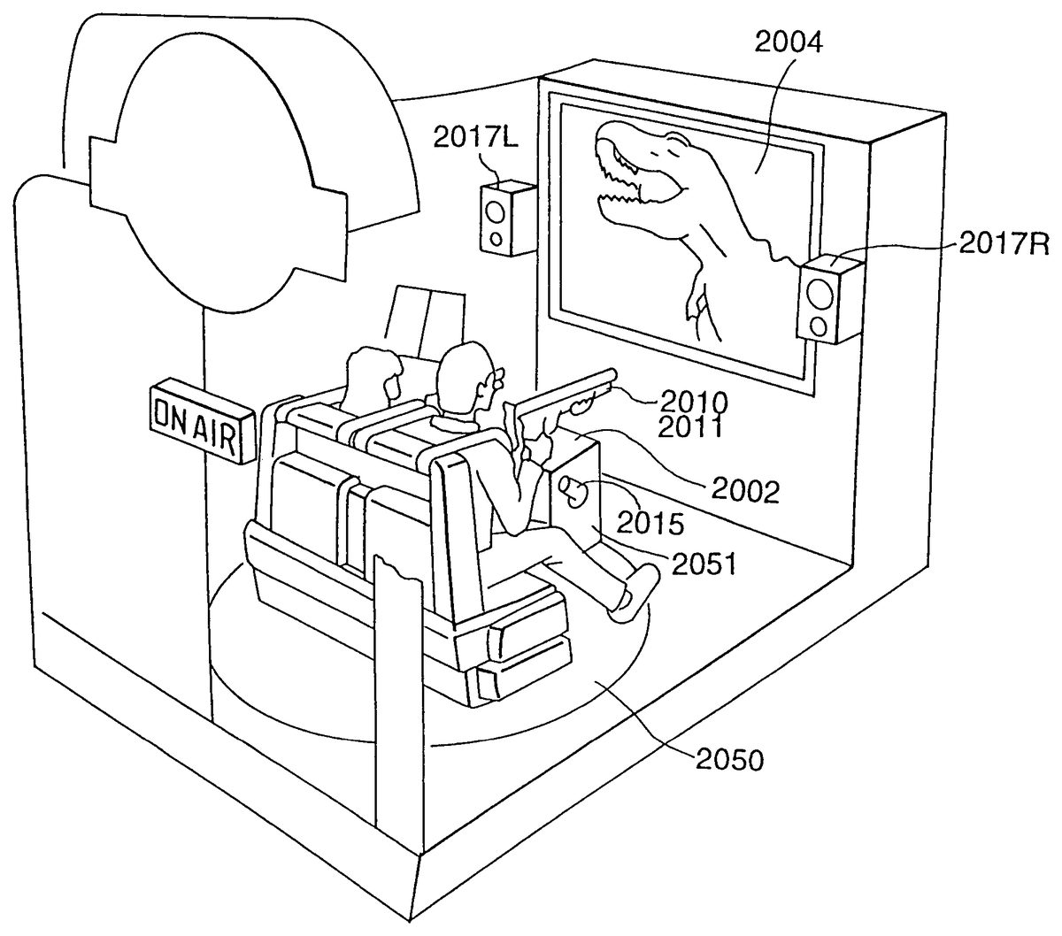
The game board2001, image processing device2003, TV monitor2004, photoreceptor elements2008, amplifier and equalizer2016, speakers2017L/R, amplifier and low pass filter2018, speakers2019L/R, amplifier and equalizer2020, speakers2021L/R, amplifier and low pass filter2022, and woofer2023are the same as or equivalent to those indicated in the first through fifth embodiments.
FIG. 35is an oblique view of a game machine in an embodiment of the present invention (a partial cutaway showing the interior). The game machine is in the form of a box, the interior of which becomes dark when the player closes the door. A rotating platform (turn table) is located about in the center of the game machine, and a seat accommodating two players is attached on top. As the rotating platform2050turns, the players variously face the front and back and to the left and right. A pedestal2051is located in front of the players. Holsters for accommodating the game guns2010and2011and air blowing holes2015are located in the pedestal. A valve unit2013is provided in the interior.
FIG. 36is a perspective diagram illustrating the operation of the rotating platform2050. The pedestal2051is not shown in this diagram. The vibration means2025is located just at the feet of the players on the rotating platform2050. In the past, this type of vibrating means2025was often located in the seat (part touching the waist), but since the sensation in the waist area is relatively acute, the vibrations end up being felt only in this part of the body and cannot be felt throughout the entire body, with a diminished sense of actually being in the scene. Since, by contrast, the sensation in the feet is not all that acute, vibrations can be felt throughout the entire body as a result of the layout in the locations inFIG. 36. This structure can produce the sensation of shaking ground.
FIG. 37is a schematic plan of the game machine. In the figure, an entrance2052is located on the side opposite the TB monitor2004, with the rotating platform2050in between.FIGS. 36 and 37reveal that speakers2017L/R are located on the TV monitor2004side, and that speakers2021L/R are located on the entrance2052side(back side). The woofer2023is located under the screen of the TB monitor2004.
FIG. 38is a cross section depicting the detailed structure of the recoil generating device2011.FIG. 39depicts the recoil generating device2011attached to the game gun2010. As shown in the figures, the external shape of the recoil generating device2011is patterned on a gun sight scope, and thus will not seem strange when attached to the game gun2010. The recoil generating device2011is equipped with a cylinder2011A, a weight2011B that moves inside the cylinder2011A, an elastic member (coil spring in the figure)2011C for pressing the weight2011B against a cushion2011D when no air is introduced, an empty component2011E (the empty component facilitates operation) communicating with the cylinder2011A by way of the cushion2011D, and a feed tube2011F for introducing air through the empty component2011E into the cylinder2011A. When no air is introduced, the weight2011B is at the right end, but when air is introduced, the pressure moves the weight to the left side. The recoil action of this operation provides the game gun2010with recoil just as if a bullet had been fired. The intensity of the recoil can be adjusted by varying the air pressure, heaviness of the weight2011B, inside diameter of the cylinder2011A, and the spring constant of the elastic member2011C.
After air has been introduced, the other end of the feed tube2011F not shown in the figure is opened to the atmosphere, and the air in the cylinder2011A is discharged into the atmosphere. As a result, the weight2011B is pressed against the cushion2011D and is returned to its original state.
In order to effect the aforementioned operations, the valve unit2013is operated in the following manner under the control of the game board2001. When the trigger of the game gun2010is pulled, the microswitch236is activated, and prescribed signals are sent to the game board2001. The game board2001immediately opens the electromagnetic valve of the valve unit2014to connect the feed tube2011F to the air feed source2012. The period for which it is connected varies according to the degree of recoil. The other electromagnetic valve of the valve unit2014is then opened to open the feed tube2011F to the atmosphere. When air has been extracted into the cylinder2011A, the electromagnetic valve is closed. This series of operations takes a short time of no more than 1 second, for example. The operating time can be adjusted to adjust the magnitude of the recoil, the firing interval, or the like.
In the example given inFIGS. 38 and 39, recoil and reciprocation are accomplished by the combination of the cylinder and elastic member, but the cushion2011D, empty component2011E, and feed opening2011F may also be provided symmetrically on both sides of the cylinder, as shown inFIG. 42. No elastic member is needed in this structure. Various levels of recoil can be created by adjusting the opening position of the value units connected to the feed openings at both ends.
Recoil generating devices2011that use air can be made more compact and light-weight than when a solenoid coil is used. This provides considerable advantages when attached to the game gun as shown inFIG. 39.
Since the recoil generating device protrudes, a cushion should be attached for better safety.
The operations are described below.
The game machine in this embodiment rotates and vibrates the seat (ride), blows air, and the like in addition to showing the game screen, making it possible to provide a game in which the player feels even more strongly a sense of being in the scene. The game board2001performs the various types of control described above in addition to processing signals from the game gun and controlling the screen. These points are described below with reference to the flow charts inFIGS. 40 and 41.
FIG. 40is a flow chart summarizing the process. When the situation normally played in the game changes (S21), the situation at that time is determined (S22). It is determined whether or not the situation requires processing for that situation (S23), and the procedure moves on to step S24when processing is required (YES). When it is not required (NO), the procedure returns to step S21, and the game continues. In step S24, (1) a screen is generated and displayed, (2) the ride is driven, (3) and special effects are executed, as warranted by the situation.
FIG. 41is a more detailed flow chart of the process from steps S22through S24inFIG. 40. First, a determination1is made as to whether or not the ride is to be driven (S31), and when the ride is not to be driven, the normal game is processed (S32), whereas when the drive is to be driven, the ride is driven at the prescribed speed and angle (S33), and images are processed in accordance with the movements of the ride (S34). Steps S33and S34may be done in reverse or simultaneously. The four following types of ride movements are possible.
(1) Position Change
For example, when the game begins or ends, the seat can be rotated from the entrance to the screen or the opposite. The rotating platform2050at this time moves considerably (about 180 degrees).
(2) When the Vehicle in Which the Player is Traveling Moves During the Game
Examples include one large shake when the vehicle turns corners, a swinging type of shaking when crossing a suspension bridge, a jiggling type of shaking when traveling a gravelly road, a considerably jolting type of shaking when traveling rough roads, and turning the handle to escape from the enemy. The shaking preferably tilts a maximum of 45 degrees from the center. That is because the angle must allow the player to fire the gun.
(3) When Players Are Eaten by Enemies
When, for example, a player fights a dinosaur appearing on the screen but is eaten by the dinosaur, the rotating platform moves slowly to a considerable extent in a manner congruent with the movement of the dinosaur's mouth on screen.
(4) When a Player Sustains Damage
Examples include when a dinosaur strikes the vehicle in which the player is riding on screen, or when a player strikes an impediment on screen. In such cases, the extent of rotation is determined according to the size, speed, or movement of the encountered object.
A status determination2is then made as to whether or not to execute special effects (S35), and the procedure returns to the initial process to repeat the series of processes when no special effects are to be executed (S36).
Images are processed in accordance with the movements of the ride (S34), but in the case of (2), (3), and (4) above, the display images change with the movement of the seat. For example, when the direction of the vehicle changes to flee from an enemy, the enemy which was seen ahead is now seen to the side, and the images are displayed accordingly. At this time, the direction in which the player is facing does not face the screen. This makes it difficult to aim with the game gun2010at the enemy, but this all the more enhances game enjoyment. The extent to which the rotating platform2050actually rotates at this time may, but does not have to be, completely aligned with the extent to which the display images change. For the sake of enhancing game enjoyment, it is preferably not completely aligned. For example, if the rotating platform2050is rotated 180 degrees when the car handle is turned 180 degrees, the player will be facing away from the screen, making it extremely difficult to shoot, so it can actually be rotated 360 degrees, or reciprocally rotated 180 degrees, or alternatively the screen display can be aligned to 180 degrees of rotation. Conversely, when the vehicle crosses a suspension bridge, more shaking than would actually be the case can further heighten the sense of actually being in the scene.
A specific example applying the aforementioned processing from the beginning to the end of a game is given.
(Game Not Started) Nothing is displayed on the screen, and the seat faces the entrance. The seat safety bar is up.
(Getting Ready to Start Game) The safety bar drops down when players take a seat. Players hold game guns2010. The door closes. When this state has been determined, the sounds of a closing door and a key turning come from the speakers as special effects.
(Game Begins) After the sound effects, the seat is rotated by the rotating platform2050to face the screen.
(Game Stage Cleared) The seat is rotated to face the entrance to get ready for the beginning of the next stage.
(Ride Ends, Game Over) A map and the game results are displayed. The seat is then rotated to face the entrance and encourage the players to depart.
(When the Ending Has Been Reached) The ending screen is displayed with special effects. Game results are also displayed. The outcome of the game is displayed.
The following are cases of air jet special effects. (1) When the enemy roars, according to magnitude and duration, (2) when the enemy spits poison, (3) when the enemy appears from under water, (4) when a helicopter approaches, (5) when an explosion occurs, (6) when a door or passageway opens, and (7) when a glass window breaks.
INDUSTRIAL APPLICABILITY
As described above, in the present invention, the position of the view point is established based on the situation between predetermined objects defined in three-dimensional virtual space, making it possible to provide an image processing unit which is capable of displaying images suitable for given situations and which displays more exciting images that are easier to manipulate. It is also able to provide a screen that is easier to see and play.
Also in the present invention, the screen is divided into a plurality of areas for a plurality of players in a shooting game that can be played by a plurality of players, the plurality of divided areas are matched with the plurality of players, and a back-up score calculating means is provided to calculate the back-up score based on the shooting results on a player's own screen and the shooting results on another player's screen, allowing players to be rated according to the aforementioned back-up score, which makes the game more interesting.
The present invention also makes it possible to provide a game device in which the game presentation is not limited, allowing a variety of presentation images to be realized.
The present invention is also equipped with position calculating means for calculating the coordinate position of a peripheral device relative to the display screen in real time, and is also equipped with presentation changing means for changing the game presentation displayed on the display screen on the basis of the calculated results, allowing the sighting position of the muzzle to be computed or detected in real time, that is, in shorter fixed periods of times such as every 1/60th second, which is the imaging time, for example, so that the game presentation is not limited, and a variety of presentation images can be realized.
In the present invention, the aforementioned game gun is equipped with a recoil generator for simulating recoil when the game gun is fired, allowing the player to experience recoil while firing the gun, with a heightened sense of actually being in the scene.
Since the aforementioned recoil generator in the present invention is operated by air, it can be made more compact, more light-weight, and more reliable.
The present invention is equipped with a booth for housing players, a television monitor disposed in front of players in a fixed location inside the aforementioned booth, a plurality of speakers disposed around the players seated in the aforementioned specific location, speaker driving means constituting independent sound sources for each of the aforementioned plurality of speakers and for creating integrated stereo sound effects, image control means for projecting images on the aforementioned television monitor, and central control means for outputting designated signals to the aforementioned speaker driving means and the aforementioned image control means as the game unfolds and for allowing the game to advance while synchronizing the sounds and images, so that the central control means creates stereo sound effects by outputting the designated signals to the speaker driver means and image control means as the game unfolds and by independently driving the speakers surrounding the players while synchronizing the sounds and images, thereby allowing players to experience stereo sound effects corresponding to the game situation which changes in real time. The plurality of speakers disposed around the players are driven and controlled using the various independently formed sound sources, allowing the location of sounds around the players to be freely altered to reproduce extremely realistic stereo sounds, and allowing more effective stereo sound effects to be realized while synchronized with the images on the television monitor. Since no headphones are used, the troubles associated with wearing them are eliminated. The players in the booth are isolated from the external world, and are also visually and acoustically separated from external factors, allowing the stereo sound effects to be even further enhanced.
The present invention is equipped with vibration means situated at the feet of the player in the aforementioned specific location and a vibration driving means for driving the aforementioned vibration means, wherein the aforementioned vibration driving means produces vibrations by driving the aforementioned vibration means by means of designated signals from the aforementioned central control means, the central control means creates stereo sound effects by outputting designated signals as the game unfolds to the speaker driving means and image control means, and by matching the sounds and images, while at the same time outputting designated signals to the vibration driving means as the game unfolds to drive the vibration means and vibrate the feet of the player, thereby making for an even more realistic and exciting experience.
The present invention is also equipped with a booth for housing a player, a display component located inside the aforementioned booth, image generating means for generating images displayed on the aforementioned display component, rotation means for rotating the direction in which the aforementioned player is facing, and rotation control means for rotating the aforementioned rotation means, wherein the aforementioned rotation control means rotates the aforementioned rotation means as the game unfolds, and the aforementioned image generating means changes images according to the rotation, so that the players are rotated along with the movements of the characters in the game scenario, and the images are changes with the rotation, further heightening the sense of being in the scene.
The present invention is also equipped with a booth for housing a player, a display component located inside the aforementioned booth, image generating means for generating images displayed on the aforementioned display component, and special effects generating means for giving special effects to heighten the player's sense of being in the scene as the game unfolds, resulting in a more exciting experience with unexpected effects for players.
Claims
- A game machine, comprising: a booth;a display component disposed in said booth;an image generating device configured to generate images to be displayed on said display component;a game gun configured to be aimed and fired at selected ones of the images generated by the image generating device;a reaction generating mechanism configured to provide a recoil action to a player when said game gun is fired, wherein said reaction generating mechanism comprises: a cylinder having first and second end portions;a movable member disposed in said cylinder;first and second valve units connected to the first and second end portions of said cylinder via first and second air supply tubes, respectively;and an air supply connected to said first and second valve units via the first and second air supply tubes, said first air supply tube being connected to said first end portion of said cylinder and said second air supply tube being connected to said second end portion of said cylinder;wherein said movable member reciprocates in said cylinder by air pressure controlled by opening and closing movement of the first and second valve units in accordance with the firing of the gun;and various levels of recoil are created by adjusting an opening position of the first and second valve units;a rotating platform disposed in said booth and configured to seat a player, wherein said rotating platform is configured to rotate about an axis that is substantially perpendicular to a radial direction of the rotating platform;and a rotation controller configured to rotate said rotating platform;wherein said image generating device changes images as the game unfolds;and said rotation controller rotates said rotating platform on the axis according to the change of the images.
- The game machine according to claim 1 , further comprising: a special effects generator configured to provide special effects to heighten the player's sense of being in a scene as the game unfolds.
- The game machine according to claim 2 , wherein said special effects generator discharges air at said player.
Disclaimer: Data collected from the USPTO and may be malformed, incomplete, and/or otherwise inaccurate.