U.S. Pat. No. 7,402,110
INTERACTIVE VIDEO GAME
Issue DateNovember 10, 2006
Illustrative Figure
Abstract
A gimbaled wheel video amusement ride is disclosed.
Description
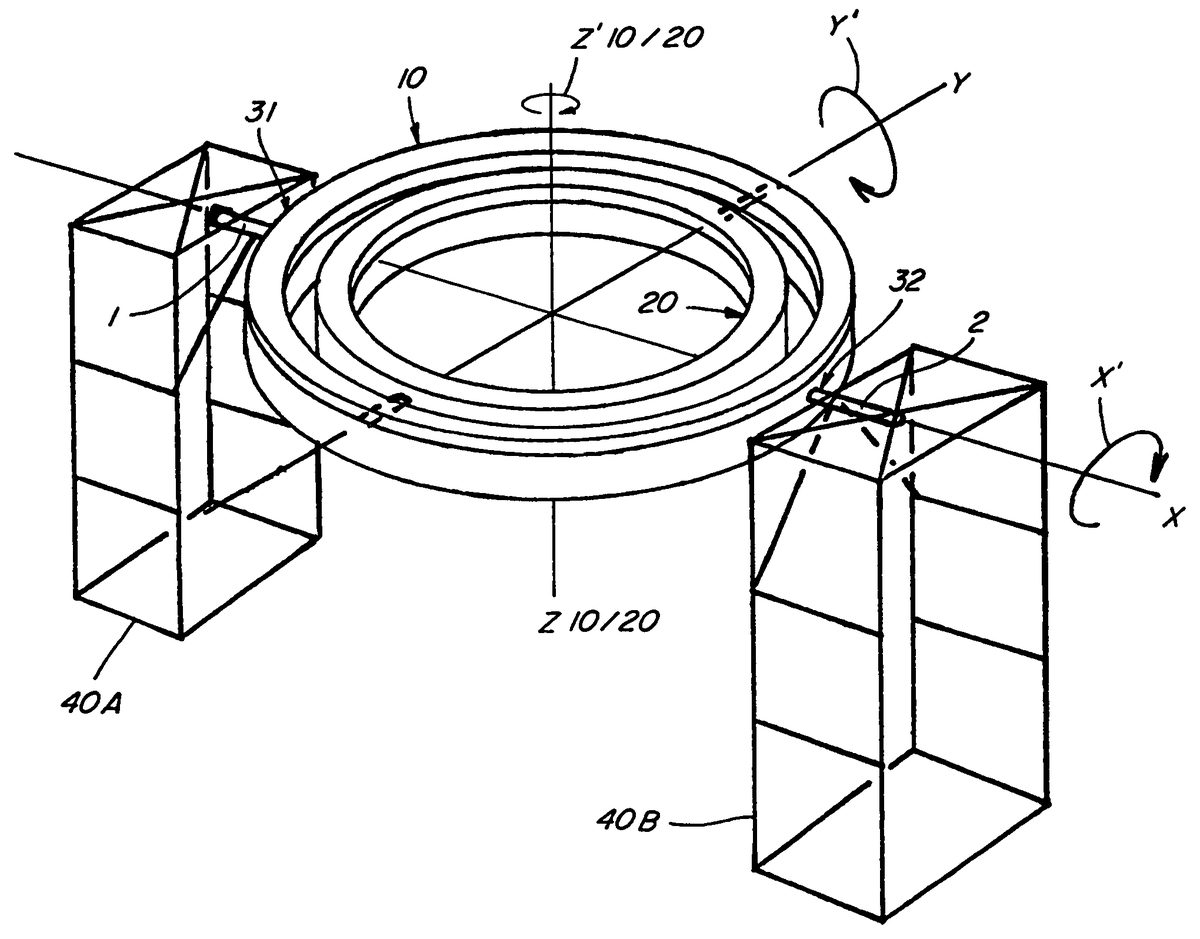
DETAILED DESCRIPTION AND PREFERRED EMBODIMENTS Generally, the apparatus of this invention as shown inFIG. 1comprises an outer wheel10, having gimbaled therein at least one inner wheel20. Outer wheel10preferably is supported by framework30at each of two outer wheel sections31and32via shafts1and2, respectively. Wheels10,20and potential additional internal wheel300(shown onFIG. 2) may be constructed using any of various suitable designs. The wheels may resemble solid rims or have hollow construction or as preferred may embody the construction inFIG. 15with crisscrossed reinforcements, i.e. a super structure similar to bridge supports or Ferris wheels. Refer now toFIGS. 2,4a,15,16,17,19, and22. Drive shaft1extends horizontally from power source100, at its one end, while being fixed at its opposite end to outer wheel10, at drive section31. Static gear shaft2is affixed onto support structure40B. Static gear shaft2extends horizontally between vertically disposed static gears3A and3B, while resting revolvably in bushing4, in opening5, of the outer wheel10's first static section32. Thus, outer wheel10can support at least one passenger car200(FIG. 22) while power source100(FIG. 2) drives shaft1, which in turn causes outer wheel10to revolve transversely, about axis X, along a path X′. The static shaft2, being located 180° from the drive shaft1, is disposed to also assist outer wheel10to revolve about axis X. Static gears3A and3B engage outer ring gears6A and6B (FIGS. 16 and 17) which outer ring gears are disposed to rotatably envelope (seeFIG. 15) substantially the entire periphery of the outer wheel10. The ring gears6A and6B are affixed to a carriage member7by a plurality of support members such as8A and8B (which can be designed as a single extensive support if desired), so as to slide via roller members9A,9B,9C,9D,9E, and9F, about the periphery of outer wheel10, in tandem with the rotation of the ring gears6A and6B, while the ring gears walk engagingly around the periphery of vertically disposed static gears3A and3B. This allows ...
DETAILED DESCRIPTION AND PREFERRED EMBODIMENTS
Generally, the apparatus of this invention as shown inFIG. 1comprises an outer wheel10, having gimbaled therein at least one inner wheel20. Outer wheel10preferably is supported by framework30at each of two outer wheel sections31and32via shafts1and2, respectively. Wheels10,20and potential additional internal wheel300(shown onFIG. 2) may be constructed using any of various suitable designs. The wheels may resemble solid rims or have hollow construction or as preferred may embody the construction inFIG. 15with crisscrossed reinforcements, i.e. a super structure similar to bridge supports or Ferris wheels.
Refer now toFIGS. 2,4a,15,16,17,19, and22. Drive shaft1extends horizontally from power source100, at its one end, while being fixed at its opposite end to outer wheel10, at drive section31. Static gear shaft2is affixed onto support structure40B. Static gear shaft2extends horizontally between vertically disposed static gears3A and3B, while resting revolvably in bushing4, in opening5, of the outer wheel10's first static section32. Thus, outer wheel10can support at least one passenger car200(FIG. 22) while power source100(FIG. 2) drives shaft1, which in turn causes outer wheel10to revolve transversely, about axis X, along a path X′. The static shaft2, being located 180° from the drive shaft1, is disposed to also assist outer wheel10to revolve about axis X. Static gears3A and3B engage outer ring gears6A and6B (FIGS. 16 and 17) which outer ring gears are disposed to rotatably envelope (seeFIG. 15) substantially the entire periphery of the outer wheel10. The ring gears6A and6B are affixed to a carriage member7by a plurality of support members such as8A and8B (which can be designed as a single extensive support if desired), so as to slide via roller members9A,9B,9C,9D,9E, and9F, about the periphery of outer wheel10, in tandem with the rotation of the ring gears6A and6B, while the ring gears walk engagingly around the periphery of vertically disposed static gears3A and3B. This allows the outer ring gears6A and6B to rotate axially around axis Z10in the path designated as Z′10, (FIG. 4a) as outer wheel10revolves transversely about axis X. Note that certain rollers slide along tracks11A and11B (FIGS. 15,16, and16a) which are integrally fixed to the outer wheel10frame work12aand12b(FIG. 16). This embodiment of the invention atFIG. 16shows rollers9C and9F are integrally attached to the tracks11B and11A respectively, and therefore roll along top surfaces SB and SA of the outer ring gears6B and6A respectively, which surfaces are opposite of the teeth of the ring gears6B and6A. The other rollers9A,9B,9D and9E are actually integrally attached to the carriage7or the carriage supports8A or8B. However, this roller system can be designed to accommodate other suitable embodiments if desired. Other alternatives to rollers, for enabling the carriage7to slide along the tracks11A and11B may be employed if desired.
FIG. 12Aillustrates a preferred video game embodiment of the invention. A ground level foundation500may be, for example, a concrete slab which surrounds a cylindrical concrete underground foundation501, and which supports a domed top503. This would allow the path of travel for a passenger following the route P′20on the inner wheel20and P′10on the outer wheel10, to traverse within an enclosed dome502which comprises video displays that simulate for example outer space and galactic images.
Alternatively, each passenger can may have a separate interactive display, thus allowing passengers to choose the form of environment within their respective passenger cars.
Referring particularly toFIGS. 18,19,20and21, the gimbaled relationship between outer wheel10and inner wheel20is illustrated and the invention's preferred embodiments are further set forth. There is a transfer shaft13extending through bushing14in opening15of outer wheel10and fixedly connected to vertically disposed transfer gears16A and16B at one end, while fixedly connected to inner wheel20at its opposite end. The section33of outer wheel10, through which inner wheel transfer shaft13extends into opening15, is referred to as outer wheel transfer section33, while the section34of inner wheel20, where transfer shaft13is affixed, is referred to as inner wheel transfer section34. Transfer shaft13therefore, when disposed horizontally, serves to establish a second transverse horizontal axis, i.e. Y. Accordingly, as the tandem axial rotation of carriage7and outer ring gears6A and6B proceeds about axis Z′10, the outer ring gears6A and6B engage vertically disposed transfer gears16A and16B respectively which, in turn, causes transfer shaft13to revolve, and causes a transfer of power to inner wheel20which revolves transversely about axis Y. The transfer point33on outer wheel10is 90° from the static point32of outer wheel10.
AtFIG. 18, as inner wheel20revolves transversely about axis Y, inner wheel20at its section35, via opening21, also revolves around a second static shaft22which is securely affixed to outer wheel10at a second static point36. At an end of the static shaft22, opposite point36of outer wheel10and at static point35of inner wheel20, shaft22extends through dual static gears23A and23B about which walks dual inner wheel ring gears24A and24B respectively during the course of inner wheel20's transverse revolution about axis Y. As they walk, the inner ring gears24A and24B, which are intimately connected to carriage25via supports26A and26B, slideably engage with tracks27A and27B. Accordingly, as the ring gears24A and24B walk around static gears23A and23B, carriage member25rotates axially about axis Z20by way of the path Z′20(seeFIGS. 5 and 5a). Inner wheel rollers28A,28B,28C,28D,28E and28F enable the sliding axial rotation of carriage25. Rollers28C and28F are actually connected to the tracks27B and27A respectively and thus roll along the top surfaces of ring gears24B and24A respectively, while other inner ring rollers such as28A,28B,28D, and28E are integrally connected to carriage25via supports26B and26A, and roll along tracks27B and27A. There is also preferably a bushing29disposed within opening21for which a more effective transverse revolution of inner wheel20can occur about shaft22.
AtFIGS. 16 and 16aadditional views of the static gear position32may be seen.FIG. 16illustrates an embodiment for hydraulic or pneumatic cylinder41which actuates ram42which, in turn, actuates locking number43into position for locking of outer wheel10by engaging the wheel at32. Note carriage connector7A shown inFIG. 16amay be a continuous member for connecting the lateral bars designated as carriage7.
If desired, additional inner wheels, such as inner wheel300, may be employed as depicted inFIG. 2. Such inner wheels as inner wheel300may be gimbaled as a mirror image of the previously described gimbals via for example transfer shaft400and transfer gears401A and401B, static shaft500, all shown inFIG. 2.
FIGS. 22 and 23show particular embodiments of passenger cars200and201supported by or suspended from carriages7and25. It should be noted that in an alternative embodiment the passenger cars can be entrained together as for example roller coaster type seating, or the cars200and201may themselves be gimbaled within a frame suspended within carriages7and25.
Whereas the present invention has been described with respect to the specific embodiments illustrated, it will be understood that various changes and modifications will be suggested to one skilled in the art and it is intended to encompass such changes and modifications as fall within the scope of the invention. Not the least of those modifications are equivalent embodiments for achieving the power features of the present invention including but not limited to Servo mechanisms, hydraulic pump systems, pneumatic systems, etc. Shafts and gears may be in some cases ball bearings, rack and pinion etc. Additionally, the gear mechanism including but not limited to the static gear, the transfer gear, and the ring gears, may be assisted by chains or substitution may be achieved through belt and pulley mechanisms, hydraulic fluid components, pneumatic components, electronic components, and others all of which are within contemplation of the present invention. Furthermore it would be understood that the novel ride sensation provided by the novel amusement ride of the present invention may be simulated digitally and provided in the form of an interactive video game or other games simulating the path of travel of passengers enjoying the amusement ride of the present invention.
Claims
- An interactive video game comprising simulating the paths of travel of at least two wheels gimbaled, one within the other, and each wheel having a least one different passenger car engaged to travel along that wheels' periphery, at least one of the wheel's path of travel for its cars comprises travel about at least 3 axes, and at least two of the wheel's path of travel for its respective cars comprises travel about at least 2 axes.
- An interactive video game comprising: a support structure, a first closed loop track, a first coupling mechanism associating said first closed loop track with said support structure, said first coupling mechanism including a first drive mechanism operable to effect rotational movement of said first closed loop track about an axis of rotation, a second closed loop track disposed interiorly of said first closed loop track, a second coupling mechanism associating said second closed loop track with said first closed loop track, said second coupling mechanism including a second drive mechanism operable to effect rotational movement of said second closed loop track about an axis of rotation, said axis of rotation of said second closed loop being distinct from said axis of rotation of said first closed loop track, at least one passenger module coupled to said second closed loop track and movable therealong, a third drive mechanism operable to effect movement of said passenger module along said second closed loop track, and an interconnected video display operable and viewable by a passenger in the passenger module to show scenes of outer space, whereby simultaneous operation of said first, second, and third drive means subjects said passenger module coupled to said second closed loop track to continuing movements through three degrees of motion as said passenger module traverses said second closed loop track, and said video display being integral to the operation.
Disclaimer: Data collected from the USPTO and may be malformed, incomplete, and/or otherwise inaccurate.