U.S. Pat. No. 7,371,176
GAME CONTROLLER WITH VIBRATION MOTOR
AssigneeMitsumi Electric Co., Ltd.
Issue DateOctober 17, 2002
Illustrative Figure
Abstract
A controller includes a case body, a vibration motor for vibrating the case body, a slide switch operated by a side button disposed on a side face of the case body, a contact board of the slide switch and a wiring board, including a holder holding the vibration motor and the contact board. The slide switch and the holder is provided on a first face of the wiring board.
Description
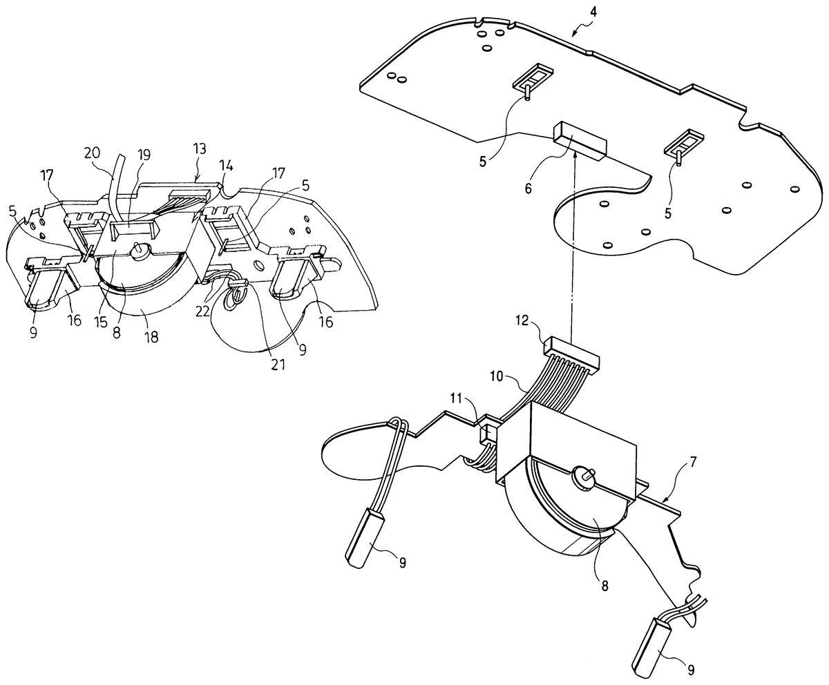
DETAILED DESCRIPTION OF THE PREFERRED EMBODIMENTS An embodiment of the invention is described in detail with reference toFIGS. 1 and 2. Incidentally, for convenience of description, each of constituent parts thereof, which is the same as the corresponding part of the related controller, is designated by the same reference numerals used for denoting the latter part of the related controller. Further, the description of such constituent parts are omitted. Moreover, the state illustrated inFIG. 3used for describing the related controller is also common to the embodiment of the invention. Thus, this figure is described, simultaneously with the description ofFIGS. 1 and 2. InFIGS. 1 and 3, a holder14for holding a vibration motor8and contact boards9for a side button is provided on the bottom face of a wiring board13to be accommodated in an upper case1 A vibration motor holding portion15for press-holding an upper half portion of the vibration motor8is provided in this holder14in such a way as to extend in a protruding direction in which the portion15protrudes from the wiring board13. Contact board holding portions16for holding the contact boards9in a perpendicular direction are disposed on the lateral sides of this vibration motor holding portion15in such a manner as to extend in a protruding direction in which the holding portions16protrudes from the wiring board13, similarly as the vibration motor holding portion15. Furthermore, each of slide switch holding portions17for holding a corresponding one of slide switches5are respectively provided nearly at a middle portion between the vibration holding portion15and a corresponding one of the contact board holding portions16. Thus, the controller is configured so that most of wiring boards are accommodated in the upper case1, that other wiring boards are accommodated in this upper case1, and that no wiring boards are accommodated in the lower case3. Incidentally, rubber18is wound around the outer periphery of the ...
DETAILED DESCRIPTION OF THE PREFERRED EMBODIMENTS
An embodiment of the invention is described in detail with reference toFIGS. 1 and 2. Incidentally, for convenience of description, each of constituent parts thereof, which is the same as the corresponding part of the related controller, is designated by the same reference numerals used for denoting the latter part of the related controller. Further, the description of such constituent parts are omitted. Moreover, the state illustrated inFIG. 3used for describing the related controller is also common to the embodiment of the invention. Thus, this figure is described, simultaneously with the description ofFIGS. 1 and 2.
InFIGS. 1 and 3, a holder14for holding a vibration motor8and contact boards9for a side button is provided on the bottom face of a wiring board13to be accommodated in an upper case1
A vibration motor holding portion15for press-holding an upper half portion of the vibration motor8is provided in this holder14in such a way as to extend in a protruding direction in which the portion15protrudes from the wiring board13. Contact board holding portions16for holding the contact boards9in a perpendicular direction are disposed on the lateral sides of this vibration motor holding portion15in such a manner as to extend in a protruding direction in which the holding portions16protrudes from the wiring board13, similarly as the vibration motor holding portion15. Furthermore, each of slide switch holding portions17for holding a corresponding one of slide switches5are respectively provided nearly at a middle portion between the vibration holding portion15and a corresponding one of the contact board holding portions16.
Thus, the controller is configured so that most of wiring boards are accommodated in the upper case1, that other wiring boards are accommodated in this upper case1, and that no wiring boards are accommodated in the lower case3.
Incidentally, rubber18is wound around the outer periphery of the vibration motor8. This vibration motor8is held by the holder14through the rubber18. Moreover, a lower portion of the vibration motor8is supported by the lower case3so as to come into contact therewith. Further, the vibration of the vibration motor8is transmitted to the lower case3through the rubber18.
Thus, the vibration motor8and the contact board9can be wire-connected directly to the wiring pattern provided on the wiring board13. Therefore, there is no need for using the connecting cable and the connector, which are used in the related controller. Consequently, the configuration of the controller is simplified. Moreover, the assembling thereof is facilitated. Thus, the invention can contribute to reduced cost.
Further, the wiring board13is accommodated in the upper case1. No wiring board is accommodated in the lower case3. Thus, even in the case that the vibration motor8and the bottom portions of the contact boards9are provided in such a way as to protrude to the lower case3, the vibration motor8and the bottom portions of the contact boards9do not touch an obstacle when the upper case1is fitted into the lower case3. Further, a cable for connecting between the upper case and the lower case is not used. This eliminates the necessity for connecting the wire to the connector.
Furthermore, as shown inFIG. 2, a protruding portion19is provided at a predetermined place on the vibration motor holding portion15of the holder14in such a way as to be located at a predetermined distance from and in parallel to the wiring board13. This protruding portion19is configured so that a part of a cable20to be connected to the wiring board13is accommodated between the protruding portion19and the wiring board13by being loosely fitted thereinto. Thus, even when this cable20is externally pushed into the controller, the cable20can be restrained by the protruding portion19from being pushed thereinto. Moreover, the cable20can be prevented by the protruding portion19from being entangled and twisted in the case.
Further, inFIG. 2, a wire locking portion21is provided in the vicinity of the vibration motor holding portion15of the holder14, and is formed like a hook. A wire22connecting the vibration motor8to the wiring board13is reliably locked by the wire locking portion21. Thus, the wire22is prevented from being entangled and twisted.
Incidentally, various modifications may be made without departing from the spirit of the invention. Further, the invention covers such modifications as a matter of course.
Claims
- A controller comprising: a case body;a vibration motor for vibrating the case body;a slide switch operated by a side button disposed on a side face of the case body;a contact board of the slide switch;and a wiring board, including a holder holding the vibration motor and the contact board;wherein the slide switch and the holder are provided on a first face of the wiring board.
- The controller as set forth in claim 1 , wherein the holder includes a motor holding portion which holds the vibration motor and a contact board holding portion which holds the contact board;and wherein the motor holding portion is formed so as to protrude from the wiring board in a direction perpendicular to an extending direction of the wiring board.
- The controller as set forth in claim 2 , wherein the motor holding portion has a protruding portion protruded in a direction parallel with the extending direction of the wiring board, and the protruding portion is located away from the wiring board;and wherein a space is formed between the wiring board and the protruding portion for accommodating a part of a cable connected to the wiring board.
- The controller as set forth in claim 2 , further comprising a wiring locking portion provided on the wiring board, the wiring locking portion located at a vicinity of the motor holding portion;and wherein the wire locking portion locks a wire connecting the vibration motor to the wiring board.
- The controller as set forth in claim 4 , wherein the wire locking portion is a hook member.
- The controller as set forth in claim 1 , wherein the case body includes an upper case and a lower case;and wherein the wiring board is accommodated in the upper case of the case body.
- The controller as set forth in claim 6 , wherein a lower portion of the vibration motor contacts on the lower case.
Disclaimer: Data collected from the USPTO and may be malformed, incomplete, and/or otherwise inaccurate.