U.S. Pat. No. 7,351,148
ELECTRONIC SEQUENCE MATCHING GAME AND METHOD OF GAME PLAY USING SAME
AssigneeR R DESIGN AND DEVELOPMENT Ltd; R R Design and Dev Ltd; Hasbro Inc
Issue DateSeptember 15, 2004
Illustrative Figure
Abstract
The present invention is directed to an apparatus and a method of game play for an electronic sequence matching game the may include a pair of elongated stick member that may be operatively coupled together by an electrical cord so the game play for the electronic matching game may be coordinated between the elongated stick members. During the electronic sequence matching game, the elongated stick members may illuminate different colored lights and generate corresponding sounds in particular sequences, and a player must manipulate the sticks to repeat the sequences generated by the elongated stick members. Depending on the mode of game play, the elongated stick members may repeat the sequence with an additional light being added to the sequence each time the player successfully matches the sequence, or the elongated stick members may generate a new sequence that may be longer or played faster than the previous sequence each time the player successfully matches a sequence. In a further mode, the player may be able to manipulate the elongated stick members in any desired sequence, with the player's manipulation of the elongated stick members causing the stick members to respond with lights and sounds of the music chosen by the player.
Description
DETAILED DESCRIPTION OF VARIOUS EMBODIMENTS Although the following text sets forth a detailed description of numerous different embodiments of the invention, it should be understood that the legal scope of the invention is defined by the words of the claims set forth at the end of this patent. The detailed description is to be construed as exemplary only and does not describe every possible embodiment of the invention since describing every possible embodiment would be impractical, if not impossible. Numerous alternative embodiments could be implemented, using either current technology or technology developed after the filing date of this patent, which would still fall within the scope of the claims defining the invention. It should also be understood that, unless a term is expressly defined, in this patent using the sentence “As used herein, the term ‘——————’ is hereby defined to mean . . . ” or a similar sentence, there is no intent to limit the meaning of that term, either expressly or by implication, beyond its plain or ordinary meaning, and such term should not be interpreted to be limited in scope based on any statement made in any section of this patent (other than the language of the claims). To the extent that any term recited in the claims at the end of this patent is referred to in this patent in a manner consistent with a single meaning, that is done for sake of clarity only so as to not confuse the reader, and it is not intended that such claim term by limited, by implication or otherwise, to that single meaning. Finally, unless a claim element is defined by reciting the word “means” and a function without the recital of any structure, it is not intended that the scope of any claim element be interpreted based ...
DETAILED DESCRIPTION OF VARIOUS EMBODIMENTS
Although the following text sets forth a detailed description of numerous different embodiments of the invention, it should be understood that the legal scope of the invention is defined by the words of the claims set forth at the end of this patent. The detailed description is to be construed as exemplary only and does not describe every possible embodiment of the invention since describing every possible embodiment would be impractical, if not impossible. Numerous alternative embodiments could be implemented, using either current technology or technology developed after the filing date of this patent, which would still fall within the scope of the claims defining the invention.
It should also be understood that, unless a term is expressly defined, in this patent using the sentence “As used herein, the term ‘——————’ is hereby defined to mean . . . ” or a similar sentence, there is no intent to limit the meaning of that term, either expressly or by implication, beyond its plain or ordinary meaning, and such term should not be interpreted to be limited in scope based on any statement made in any section of this patent (other than the language of the claims). To the extent that any term recited in the claims at the end of this patent is referred to in this patent in a manner consistent with a single meaning, that is done for sake of clarity only so as to not confuse the reader, and it is not intended that such claim term by limited, by implication or otherwise, to that single meaning. Finally, unless a claim element is defined by reciting the word “means” and a function without the recital of any structure, it is not intended that the scope of any claim element be interpreted based on the application of 35 U.S.C. § 112, sixth paragraph.
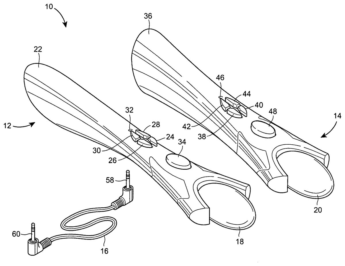
FIG. 1illustrates one possible embodiment of an electronic sequence matching game10in accordance with the invention. In the illustrated embodiment, the electronic sequence matching game10may include a first elongated stick member12and a second elongated stick member14that may be operatively coupled together by an electrical cord16so the game play for the electronic matching game may be coordinated between the elongated stick members12,14. During the matching game, the elongated stick members12,14may illuminate different colored lights within bulbs18,20and generate corresponding sounds in particular sequences, and a player must manipulate the sticks to repeat the sequences generated by the elongated stick members12,14. Depending on the mode of game play, the elongated stick members12,14may repeat the sequence with an additional light being added to the sequence each time the player successfully matches the sequence, or the elongated stick members12,14may generate a new sequence that may be longer or played faster than the previous sequence each time the player successfully matches a sequence. In a further mode, the player may be able to manipulate the elongated stick members12,14in any desired sequence, with the player's manipulation of the elongated stick members12,14causing the stick members12,14to respond with lights and sounds of the music chosen by the player. The game play modes for the electronic sequence matching game10will be further illustrated and described with reference toFIGS. 9 and 10.
Returning toFIG. 1, the first elongated stick member12may include a first elongated housing22enclosing the electronic components of the first elongated stick member12, and engaging the first bulb18to retain the bulb18proximate the lights of the first elongated stick member12such that the bulb18may be illuminated when the lights are illuminated. The housing22may be shaped such that a player may grasp the end of the housing22distal to the bulb18in a manner similar to a drumstick such that the player may shake the elongated stick member12in a similar manner to playing a drum. The first elongated stick member12may further include a plurality of buttons24,26,28,30that may be depressed to actuate switches disposed thereunder to control various aspects of the game play for the electronic sequence matching game10.
A power button24may be pressed to alternately turn on and turn off the electronic sequence matching game10. Once the power is turned on by depressing the power button24, a game select button26may be depressed by the player to select a desired one of the available games or modes of game play provided by the electronic sequence matching game10. The first elongated stick member12may further include a decrease skill level button28and an increase skill level button30. The buttons28,30may be depressed in order to play the game selected by the game select button26at a desired skill level. Increasing the skill level for a game by depressing the increase skill level button30may cause the electronic sequence matching game10to increase the maximum number of signals in a given sequence during the game play, to increase the speed with which the sequence is played for the player by the electronic sequence matching game10or otherwise increase the difficulty for the player to match the sequences. Conversely, depressing the decreased skill level button28may reduce the number of signals in the sequence and the speed with which the sequences are played, or otherwise reduce the difficulty of the game. In addition to the readily accessible buttons24,26,28,30, the first elongated housing22may include a reset button access opening32in which may be disposed a reset button (not shown) that, when depressed, may cause the electronic sequence matching game10to reset to an initial operational state and clear the historical game information stored for the electronic sequence matching game10, such as the high scores for each game mode, that may be stored therein.
The first elongated hosing22may further include a magnetic switch indicator area, such as an oval34, that may indicate the position at which a magnetic switch within the first elongated stick member12is disposed for reference by the player while playing the electronic sequence matching game10. The magnetic switch in the first elongated stick member12, and a corresponding magnetic switch in the second elongated stick member14, may cooperate in a manner discussed more fully below to signal that the first and second elongated stick members12,14are disposed proximate each other by the player during the electronic sequence matching game10.
Similar to the first elongated stick member12, the second elongated stick member14may include a second elongated housing36engaging the second bulb20, a plurality of control buttons38,40,42,44, a reset button access opening46, and a magnetic switch indicator area, such as oval48. The second elongated housing36may be configured similar to the first elongated housing22such that the player may grasp the end of the housing36distal to the second bulb20in a similar manner as a drumstick such that the player may shake the second elongated stick member14in a manner simulating the playing of a drum. Forward music mix button38and reverse music mix button40may allow the player to cycle through and select a desired one of a plurality of available background beats to be played by the elongated stick member12,14during the electronic sequence matching game10. The forward music mix button38may allow the player to cycle through the available beats in one order, while the reverse music mix button40may allow the player to cycle through the available beats in the opposite order. The volume buttons42,44increase and decrease, respectively, the volume of the sounds generated by the elongated stick members12,14. The reset button access opening46and magnetic switch indicator area48may be configured to perform similar functions as the corresponding reset button access opening32and magnetic switch indicator area34, respectively, of the first elongated stick member12.
Referring toFIG. 2, which is a bottom view of the second elongated stick member14, the elongated housing36may include a magnetic switch indicator area, such as an oval50disposed the opposite the oval48on the top of the elongated housing36and, consequently, disposed proximate the magnetic switch disposed within the elongated housing36to indicate the location of the magnetic switch for the player. The housing36may further include a plurality of openings52disposed proximate an internal speaker (not shown) such that sounds generated by the speaker may be audible to the player external to the elongated housing36. The elongated housing36may further include a cover54providing access to a battery compartment providing a power source for the elongated stick member14. In order to operatively couple the second elongated stick member14to the first elongated stick member12, the housing36may include a plug receptacle56that may be configured to receive one of the plugs58,60(FIG. 1) disposed at either end of the cord16. While not shown, the bottom of the first elongated housing22may also include similarly configured magnetic switch area, speaker openings, battery compartment cover, and plug receptacle.
FIG. 3is a block diagram of a number of components that may be incorporated into the electronic sequence matching game10. Referring toFIG. 3, the first elongated stick member12of the electronic sequence matching game10may include a first controller100implemented on a printed circuit board102and containing the game logic and sound generation data implemented via circuitry contained on the conventional printed circuit board102, with the game execution logic and sound generation data being stored directly on the printed circuit board102. It should also be appreciated that although the first controller100may be implemented on the printed circuit board102, more complex implementations of the electronic sequence matching game10may be implemented wherein the first controller100may comprise, among other components, a program memory, a microcontroller or microprocessor (MP), a random-access memory (RAM), read-only memory (ROM), and an input/output (I/O) circuit, all of which may be interconnected. It should be appreciated that the first controller100may include multiple microprocessors. Similarly, the memory of the first controller100may include multiple RAMs and multiple program memories, depending on the complexity and requirements of a specific implementation. It should also be appreciated that the I/O circuit may include a number of different types of I/O circuits, such as sound generation circuits, video generation circuit, odor generation circuitry, and the like. The RAM(s), ROM(s) and program memories may be implemented as semi-conductor memories, magnetically readable memories, and/or optically readable memories, for example.
FIG. 3illustrates that the first controller100may be operatively coupled to various electronic components corresponding to the exterior components to the first elongated stick member12discussed in relation toFIGS. 1 and 2, with each of those components being so coupled to the first controller10via a respective direct line or conductor. Different connection schemes may be used. The switches104,106,108,110correspond to the control buttons24,26,28,30disposed on the exterior of the first elongated housing22. Input signals produced by the switches104,106,108,110are output to the first controller100for processing the game execution logic. A power switch104may be closed when the power button24is depressed by the player, thereby turning on the electronic sequence matching game10, with the first controller100drawing power from a power source112, such as batteries stored within the battery compartment beneath the cover54. Depressing the power button24and, consequently, closing the power switch104when the matching game10is powered on may cause the first controller100to power down the electronic sequence matching game10. A game selection switch106, which may be actuated by depressing the game selection button26, may cause the first controller100to cycle through a plurality of available game modes offered by the electronic sequence matching game10. A decreased skill level switch108and an increase skill level110may be actuated by depressing the decreased skill level button28and increased skill level button30, respectively, to adjust the skill level of the game mode selected using switch106to the player's desired level of difficulty. A reset switch114may correspond to a reset button disposed within reset button access opening32, with the actuation of the reset switch114by depressing the reset button causing the first controller100to reset the electronic sequence matching game10to an initial operational state. Depending on the processing performed in response to actuation of the switches connected to the first controller100, the circuitry of the first controller100may generate and output sound generation command signals to an audible output device, such as a speaker116, wherein the speaker116translates the output command signals into sounds which can be heard by the participants of the electronic sequence matching game10. The general and specific technologies relating to the electronic sound generation circuitry, and the software required to run such devices, are well-known to those skilled in the electronic and software arts, and therefore the specific details of the digital processing and memory portions of such circuitry, and the specific details of any software required for this specific application will not be described further herein.
As previously discussed, the elongated stick members12,14may be manipulated by the players during game play to recreate the sequence of light and sound command signals generated by the electronic sequence matching game10. The manipulation of the elongated stick members12,14may include moving or shaking the elongated stick members12,14in a particular manner, or bringing the elongated stick members12,14into close proximity. In order to detect these manipulations, the elongated stick member12may include a plurality of input devices, such as a motion switch18and a magnetic switch120, operatively coupled to the first controller100and configured to be actuated in response to particular manipulations of one or both elongated stick members12,14. The motion switch118may be any type of switch or device known in the art that may close in response to a particular movement of the elongated stick member12such that closing of the motion switch18in response to the movement of the elongated stick member12may be detected by the first controller100. For example, the motion switch18may be installed and oriented within the first elongated stick member12such that the motion switch118may close when a player grasps the elongated housing22and shakes the elongated stick member12in a manner simulating the swinging of a drumstick to play a drum. Those skilled in the art will understand the motion switch118may be selected and installed within the elongated housing22such that the motion switch118may be closed when the elongated stick member12is manipulated with a particular desired motion such that the motion of the elongated stick member12is detected by the first controller100.
The magnetic switch120may be any type of switch capable of detecting proximity to a corresponding element disposed within the second elongated stick member14such that the closure of the magnetic switch120may be detected by the first controller100to indicate manipulation of the elongated stick members12,14placing the elongated stick members12,14in close proximity. The magnetic switch120may be installed within the elongated housing22proximate the oval34such that the position of the magnetic switch120may be identified from the exterior of the elongated housing22, and the magnetic switch120may be positioned to detect the proximity of the corresponding element of the second elongated stick member14. While the switch120is disclosed herein as being a magnetic switch, those skilled in the art will understand that the switch120may be any switch or mechanism capable of detecting proximity of the second elongated stick member14to the first elongated stick member12, such as magnetic switch as described herein, optical sensors, contact switches, and the like.
In order to provide a visual indication of the sequences, and the player's manipulation of the elongated stick members12,14, the elongated stick member12may further include at least one visual output device of illumination source capable of generating a plurality of different colored lights corresponding to the elements of the game sequences and the manipulations of the elongated stick members12,14. As one example, the illumination source may be in the form of a tri-colored LED including a red LED122, a yellow LED124and a blue LED126operatively coupled to the first controller100. The LEDs122,124,126of the tri-colored LED may be disposed within the first bulb18of the first elongated stick member12, with the first bulb18being partially or fully translucent such that the colored light may be visible from the exterior of the first bulb18when the LEDs122,124,126are illuminated. While the illumination sources are illustrated herein as light omitting diodes, it will be understood by those skilled in the art that any other visual output device or devices capable of producing the desired colored lights may be implemented for use in the electronic sequence matching game10. Further, colors other than or in additional to red, green, blue and yellow may be used in the electronic sequence matching game10to achieve a desired game play.
FIG. 3further illustrates the components that may be incorporated in to the second elongated stick member14of the electronic sequence matching game10. The second elongated stick member14may include a second controller130implemented on a printed circuit board132and containing the game logic and sound generation data implemented via circuitry contained on the conventional printed circuit board132, with the game execution logic and sound generation data being stored directly on the printed circuit board132. As with the first controller100and printed circuit board102, the second controller130and printed circuit board132may be configured in any manner, and contain the necessary components, for implementing the electronic sequence matching game10. The second controller130may be operatively connected to a forward music mix select switch134, a reverse music mix select switch136, an increase volume switch138, and a decreased volume switch140corresponding to the external control buttons38,40,42,44, respectively, of the elongated stick member14such that depressing the control buttons38,40,42,44may closed the corresponding switches134,136,138,140, respectively, to cause the second controller130to select the background music mix and volume for the sound generation command signals generated by the first and second controllers100,130and output to the first speaker116and a second audible output device, second speaker142, respectively. A reset switch144may be operatively connected to the second controller130and correspond to a second reset switch disposed within the reset button access opening46with the actuation of the reset switch144causing the first controller100and second controller130to reset the electronic sequence matching game10to an initial operational state.
The second elongated stick member14may further include input devices such as a second motion switch146and a second magnetic switch148operatively coupled to the second controller130. The second motion switch146may be similar to the first motion switch118, and may be disposed and oriented within the second elongated housing36such that the second motion switch146closes when the second elongated stick member14is manipulated in a particular manner so that the second controller130may detect the motion of the second elongated stick member14. The second magnetic switch148may be disposed within the second elongated housing36proximate the ovals48,50such that the proximity of the first magnetic switch120and the second magnetic switch148when the oval34is disposed proximate the ovals48,50the magnetic switches120,148cause each other to close, thereby causing the controllers100,130to detect that the elongated stick members12,14have been manipulated to be disposed in close proximity.
The second elongated stick member14may further include a separate power source150operatively coupled thereto to provide power to the components of the elongated stick member14when the power switch104is actuated to turn on the electronic sequence matching game10. The first controller100and second controller130may be operatively coupled by the cord16when the plugs58,60are inserted into the plug receptacles56of the elongated stick members12,14. When the power switch104is actuated to turn on the electronic sequence matching game10, the first controller100may transmit a signal to the second controller130via the cord16causing the second controller130to correspondingly turn on the second elongated stick member14under the power provided by the power source150. While the controllers100,130are illustrated herein as being operatively coupled via the hard wire connection provided by the cord16, those skilled in the art will understand that the electronic sequence matching game10may be implemented with any desired means for communications between the controllers100,130and thereby operatively couple the controllers100,130, such as infra-red communications, radio frequency communications, and the like.
As with the first elongated stick member12, the second elongated stick member14may include at least one visual output device or illumination source, such as a tri-colored LED operatively coupled to the second controller130to produce a desired plurality of colored lights indicative of the command signals of the sequences and the manipulation of the second elongated stick member14. The tri-colored LED may include a yellow LED152, a blue LED154and a green LED156disposed within the second bulb20of the second elongated stick member14. As with the first bulb18, the second bulb20may be partially or fully translucent such that the colored light from the LEDs152,154,156may be visible from the exterior of the second bulb20. As with the LEDs122,124,126, the LEDs152,154,156may be replaced by any other visual output device capable of producing a plurality of desired colors, including desired colors other than or in addition to yellow, blue and green shown in the illustrated embodiment.
As previously indicated, the colors illuminated by the LEDs122,124,126,152,154,156may correspond to the sequence generated by the electronic sequence matching game10and to the manipulation of the elongated stick members12,14by a player. The illuminated lights may further be accompanied by corresponding sounds output at the speakers116,142. In one embodiment of the electronic sequence matching game10illustrated inFIGS. 4-8, a player may be required to move the elongated stick members12,14independently or in unison to match a color illuminated by one or more of the LEDs122,124,126,152,154,156. Referring toFIG. 4, a first command signal generated by the first controller100may cause the red LED122to be illuminated such that the first bulb18may appear to turn red. At the same time, the first controller100may generate and output a sound generation command signal to the speaker116corresponding to the illumination of the red LED122that is output by the speaker116, thereby providing both a visual and an audio indication of the command signals. In this embodiment, when the first bulb18is illuminated by the red LED122, a player grasping the elongate housings22,36may be required to shake the first elongated stick member12in a manner similar to shaking a drumstick to bang a drum as indicated by the arrow158. If the player manipulates the first elongated stick member12in the appropriate manner, the movement of the first elongated stick member12may close the first motion switch18, thereby indicating to the first controller100that the first elongated stick member12has been properly shaken in response to the illumination of the red LED122. In this event, the first controller100may respond by re-illuminating the red LED122and causing the speaker116to output the corresponding sound.
In the event that the player does not properly manipulate the elongated stick members12,14, the first controller100and/or the second controller130may generate error command signals causing a different illumination of the LEDs122,124,126,152,154,156and a different sound output at the speakers116,142, respectively. For example, after initially illuminating the red LED122and outputting the corresponding sound at the speaker116, the first controller100may initiate a timer providing a pre-determined time period within which the player may properly manipulate the first elongated stick member12in response to the illumination of the red LED122. If the first controller10does not detect the closing of the motion switch118in response to the movement of the first elongated stick member12as indicated by the arrow158within the pre-determined time period, the first controller100may be programmed to terminate the player's turn and cause corresponding illuminations of the LEDs122,124,126and output of a game ending sounds at the speaker116. Additionally, the controllers100,130may identify an incorrect manipulation of the elongated stick member12,14by detecting the closing of either the motion switch146as a result of the player shaking the second elongated stick member14, or the closing of one or both of the magnetic switches120,148as a result of the player bringing the elongated stick members12,14in close proximity. Similar to the failure to manipulate the first elongated stick member12within the predetermined time period, detection of the closing of the motion switch146and/or the magnetic switches120,148may cause the controller100,130to generate an illumination of the LEDs122,124,126,152,154,156and output of sounds at the speakers116,142corresponding to an end of game condition.
Similar to the illumination of the red LED122of the first elongated stick member12, the electronic sequence matching game10may require the second elongated stick member14to be shaken by the player in a manner indicated by the arrow160(FIG. 5) within the predetermined time period when the second controller130causes the green LED156to illuminate the second bulb20and the second speaker142to generate a corresponding sound. If the player correctly manipulates the second elongated stick member14to close the motion switch146within the predetermined time period, the second controller130may cause the green LED156to be re-illuminated and the second speaker142to generate the corresponding sound. If the motion switch146does not close within the predetermined time period, or if the controllers100,130detect the closing of the first motion switch118and/or the magnetic switches120,148in response to an improper manipulation of the elongated stick members12,14by the player, the controllers100,130may cause the illumination of the LEDs122,124,126,152,154,156and output of sounds from the speakers116,142corresponding to the incorrect manipulation by the player.
InFIG. 6, the elongated stick members12,14are illustrated with the controllers100,130causing the illumination of both the yellow LEDs124,152, respectively. As with the other colors, the controllers100,130may generate command signals causing the speakers116,142, respectively, to output sounds corresponding to the yellow color of the bulbs18,20. When the bulbs18,20are illuminated by the yellow LEDs124,152, respectively, the player may be required to manipulate both the elongated stick members12,14by simultaneously shaking the elongated stick members12,14in a manner simulating the beating of a drum as indicated by the arrows162,164to close both motion switches118,146within the predetermined time period. If the controllers100,130detect the closing of the motion switches118,146within the predetermined time period, the controllers100,130may re-illuminate the yellow LEDs124,152and cause the speakers116,142to generate the corresponding sound to thereby acknowledge the correct manipulation of the elongated stick members12,14by the player. The controllers100,130may detect an improper manipulation by the player if both motion switches118,146did not close within the predetermined time period, or if the magnetic switches120and/or148close in response to the elongated stick members12,14be moved into close proximity. If the elongated stick members12,14are not properly manipulated, the controller110,130may cause an illumination of the LEDs122,124,126,152,154,156and output of sounds from the speakers116,142corresponding to an incorrect manipulation of the elongated stick members12,14.
Referring toFIGS. 7 and 8, the proper manipulation of the elongated stick members12,14in response to the illumination of the blue LEDs126,152by the controllers100,130, respectively, is illustrated. As with the other LEDs, the illumination of the blue LEDs126,154may be accompanied by the generation of corresponding sounds at the speakers116,142in response to sound generation command signals transmitted by the controllers100,130, respectively. In response to the illumination of the bulbs18,20by the blue LEDs126,154, respectively, the player may be required to cross the elongated stick members12,14such that the ovals34,48,50and, consequently, the magnetic switches120,148are placed in close proximity such that the magnetic switches120,148cause each other to close. If the controllers100,130detect the closing of the magnetic switches120,148, respectively, within the predetermined time period, the controllers100,130may cause the blue LEDs126,154, respectively, to be illuminated and the speakers116,142, respectively, to output the sounds corresponding to the illumination of the blue LEDs126,124. If the magnetic switches120,148do not close within the predetermined time period, or if the controllers100,130detect the closing of one or both of the motion switches118,146in response to shaking of the elongated stick members12,14, the controllers100,130may cause an illumination of the LEDs122,124,126,152,154,156and output of sounds from the speakers116,142corresponding to the improper manipulation of the elongated stick members12,14in response to the illumination of the blue LEDs126,154.
As previously discussed, the electronic sequence matching game10may be programmed to offer a plurality of different sequence matching games.FIG. 9illustrates one embodiment of a sequence matching game routine200that may be implemented in the electronic matching game10. The sequence matching game routine200may correspond to a game in which a player must manipulate the elongated stick members12,14to match a sequence generated by the electronic sequence matching game10. If the player successfully manipulates the elongated stick members12,14to match the generated sequence, the elongated stick members12,14may replay the same sequence and add an additional color at the end of the sequence that the player must also match the next time through the sequence. The routine200may begin at a block202wherein the player may turn on the electronic sequence matching10by depressing the power button24to close the power switch104. Once the electronic sequence matching game10is powered on, control may pass to a block204wherein the player may select the sequence matching game200by depressing the game selection button26to close the game selection switch106until the controller100may cause the speaker116to output a sound corresponding to the sequence matching game200. While not shown inFIG. 6, the player may also depress the other control buttons28,30,38,40,42,44to set the skill level, background music mix and volume to the settings desired by the players.
Once the player selects the desired sequence matching game200, control may pass to a block206wherein the player may initiate the sequence matching game. In one embodiment, the controllers100,130may be programmed such that the players may cross the elongated stick members12,14in a manner causing the magnetic switches120,148to close. Upon detecting of the closing of the magnetic switches120,148when the electronic sequence matching game10is not in the process of executing an occurrence of one of the available sequence matching games, the controllers100,130may be programmed to begin a new occurrence of the selected sequence matching game200. Once the game is initiated, control may pass to a block208wherein the controllers100,130may generate the first command signal for a particular sequence used for the occurrence of the sequence matching game200, and cause the LEDs122,124,126,152,154,156to illuminate the corresponding color, and cause the speakers116,142to output the corresponding sound for the first command signal. The sequences used during the electronic sequence matching game may be generated in any desired manner. In one embodiment, the sequences may be randomly determined by the controller100,130each time a new sequence is required. In an alternative embodiment, a plurality of available sequences may be stored at the printed circuit boards102,132for use during the electronic sequence matching game. When a new sequence is needed, the controllers100,130may select one of the available sequences randomly, sequentially or by any other appropriate method for use in the occurrence of the game. Other methods for generating and selecting sequences are contemplated as having use with the present invention.
After the first color is illuminated, and the corresponding sound is output, control may pass to a block210wherein one of the controllers100,130may start a timer for the predetermined period of time within which the player must manipulate the elongated stick members12,14. At a block212, the controllers100,130may evaluate whether any of the motion switches118,146or the magnetic switches120,148have been closed, thereby signaling manipulation of the elongated stick members12,14by the player. If the controllers100,130have not detected the closing of any of the switches118,120,146,148, control may pass to a block214wherein the controllers100,130evaluate whether the predetermined period of time for manipulating the elongated stick members12,14has expired. If the timer has expired without the player manipulating the elongated stick members12,14, control may pass to a block216wherein the controllers100,130may cause the illumination of the LEDs122,124,126,152,154,156and output of sounds from the speakers116,142corresponding to the end of the sequence matching game200. The end of game indication may include the illumination of one or more of the LEDs122,124,126,152,154,156, and the generation of command signals causing the speakers114,142to output music or other sounds, and/or simulated speech indicating that the game is over, and a player score for the occurrence of the sequence matching game200.
If the predetermined period of time for manipulating the elongated stick members12,14has not expired, control may be return to block212to evaluate whether the elongated stick members12,14have been manipulated. If the elongated stick members12,14are manipulated within the predetermined period of time, control may pass to a block218wherein the controllers100,130may determine whether the elongated stick members12,14were correctly manipulated by the player. As discussed above with respect toFIGS. 4-8, the elongated stick members12,14are correctly manipulated if the switches118,120,146,148corresponding to the illuminated colors have been closed in response to the manipulation of the elongated stick members12,14by the player. If the player does not correctly manipulate the elongated stick members12,14in the manner corresponding to the illuminated color and output sound, control may pass to the block216to illuminate the LEDs122,124,126,152,154,156and output sounds from the speakers116,142in the manner previously described.
If the player has correctly manipulated the elongated stick members12,14, control may pass to a block220wherein the controllers100,130may determine whether the electronic matching game200has reached the end of the sequence for the occurrence of the game. If the electronic matching game200has not reached the end of the sequence, control may pass to a block222wherein the controllers100,130may repeat the sequence matched by the player and add an additional command signal to illuminate the corresponding LED122,124,126,152,154,156, and to cause the output of a corresponding sound at the speakers116,142. After regenerating the sequence with the additional command signal, control may pass back to the block210wherein the controllers100,130may start the timer for the predetermined period of time, and to block212wherein the controllers100,130may evaluate whether the player has manipulated the elongated stick members12,14in an effort to match the sequence.
Once the controllers100,130detect that the player has manipulated the elongated stick members12,14, control passes to the block218to evaluate whether the player has correctly manipulated the elongated stick members12,14. It should be noted that the controllers100,130must now evaluate whether the player correctly manipulates the elongated stick members12,14to match the first command signal in the sequence followed by the second command signal in the sequence. For example, the first two command signals in the sequence may cause the illumination of the red LED122and output of the corresponding sound from speaker116, followed by the illumination of the green LED156and output of the corresponding sound at the speaker142. In order to correctly match the sequence, the player must first shake the first elongated stick member12in the manner illustrated inFIG. 4, and then shake the second elongated stick member14in the manner illustrated inFIG. 5. In order to determine that the player has correctly manipulated the elongated stick members12,14to match the sequence, the first controller100may be required to detect the closing of the motion switch118, followed by the detection of the closing of the motion switch146by the second controller130. If the controllers100,130detect the closing of the motion switches118,146in the proper sequence, the controllers100,130may be programmed to pass control to the block220to evaluate whether the player has reached the end of the sequence. The controllers100,130will continue to perform similar evaluations of the closing of the switches118,120,146,148as the length of the sequences increased and the player manipulates the elongated stick members12,14. While not shown, the controllers100,130may be programmed such that the player may be provided with a limited amount of time between manipulations of the elongated stick members12,14as the player attempts to match a subsequent command signal within the sequence after correctly matching the preceding command signal of the sequence. Once a player successfully reaches the end of the sequence at the block220, control may pass to the block216wherein the controllers100,130may cause the illumination of the LEDs122,124,126,152,154,156and output of sounds at the speakers116,142indicative of the players successful completion of the occurrence of the sequence matching game200.
FIG. 10illustrates another sequence matching game routine230that may be implemented with the elongated stick members12,14. As with the previously described routine200, the sequence matching game routine230may begin with a player powering on the elongated stick members12,14at block202, selecting the desired sequence matching game at block204, and initiating the selected game at block206. Once the sequence matching game230is initiated, control may pass to a block232where the controllers100,130generate a first sequence to be matched by the player. The first sequence may include a plurality of command signals generated by the controllers100,130, with the length of the sequence being determined, at least in part, on the skill level selected by the player. For example, the controllers100,13Q may generate a sequence wherein the controller100causes the red LED122to be illuminated, followed by the controller130causing the green LED156to be illuminated, the controllers100,130causing the yellow LEDs124,152to be illuminated, and finally the controllers100,130causing the blue LEDs126,154to be illuminated. As each of the LEDs122,124,126,152,154,156are illuminated, the controllers100,130may also cause the speakers116,142to output sounds corresponding to the illuminated colors.
Once a first sequence is generated by the controllers100,130and output at the elongated stick members12,14, the controllers100,130may start the timer at block210, and evaluate whether the stick members have been manipulated or the timer has expired at blocks212,214, respectively, in the manner previously described with respect toFIG. 9. Once the controllers100,130detect the manipulation of the elongated stick members12,14by the player, the controllers100,130may evaluate whether the elongated stick members12,14have been correctly manipulated by the player at the block218. In the above example, the correct manipulation of the elongated stick members12,14would include shaking the first elongated stick member12in the manner illustrated inFIG. 4to close the first motion switch118, shaking the second elongated stick member14in the manner illustrated inFIG. 5to cause the second motion switch146to close, shaking both elongated stick members12,14in the manner illustrated inFIG. 6to cause both motion switches118,146to close, and finally crossing the elongated stick members12,14in the manner illustrated inFIG. 8to cause the magnetic switches120,148to close. If the player does not correctly manipulate the elongated stick members12,14within the predetermined period of time, control may pass to the block216wherein the controllers100,130may generate error or game over command signals in the manner previously described. If the player correctly manipulates the elongated stick members12,14, control may pass to a block234wherein the controllers100,130evaluate whether the sequence matched by the player is the last sequence for the occurrence of the sequence matching game230. If the matched sequence is not the last sequence for the occurrence of the sequence matching game230, control may pass to a block236wherein the controllers100,130may generate the next sequence to be matched by the player during the occurrence of the sequence matching game230. The sequence matching game230may proceed in a similar manner until the player does not match a sequence, or until the player successfully matches the last sequence for the occurrence of the sequence matching game230. As previously discussed, other variations, of sequence matching games may be implemented in the electronic sequence matching game10.
Thus, while the present invention has been described with reference to specific examples, which are intended to be illustrative only and not to be limiting of the invention, it will be apparent to those of ordinary skill in the art that changes, additions or deletions may be made to the disclosed embodiments without departing from the spirit and scope of the invention.
Claims
- An electronic game for use by at least one player, comprising: a first game element having a first illumination source configured to illuminate a plurality of different colors, and a first motion switch configured to detect movement of the first game element by the player;and a second game element having a second illumination source configured to illuminate a plurality of different colors, and a second motion switch configured to detect movement of the second game element by the player, wherein the first and second game elements are physically separate game elements that may be moved by a player independently of each other, and wherein the second game element is operatively coupled to the first game element, wherein each of the plurality of colors illuminated by the first and the second illumination sources corresponds to a particular movement of at least one of the first and the second game elements by the player, and where the first and second motion switches are configured to compare the movement of the first and second game elements by the player to the particular movement corresponding to an illuminated one of the plurality of different colors.
- An electronic game as defined in claim 1 , wherein the first and second game elements are configured to cause the first and second illumination sources to illuminate at least one of the plurality of different colors in a particular sequence, and wherein the first and second motion switches are configured to compare the sequence of the detected movement of the first and second game elements to the particular sequence of illuminating the at least one of the different colors.
- An electronic game as defined in claim 2 , wherein the first and second game elements are configured to cause the first and second illumination sources to illuminate the at least one of the plurality of different colors in the particular sequence and to illuminate an additional one of the plurality of different colors after the particular sequence in response to determining that the sequence of movement of the first and second game elements detected by the first and second motion switches corresponds to the particular sequence of illuminating the at least one of the different colors.
- An electronic game as defined in claim 2 , wherein the first and second game elements are configured to cause the first and second illumination sources to illuminate the at least one of the plurality of different colors in a second particular sequence in response to determining that the sequence of movement of the first and second game elements detected by the first and second motion switches corresponds to the particular sequence of illuminating the at least one of the different colors.
- An electronic game as defined in claim 2 , wherein the first and second game elements are configured to cause the first and second illumination sources to illuminate the at least one of the plurality of different colors in a game ending sequence in response to determining that the sequence of movement of the first and second game elements detected by the first and second motion switches do not correspond to the particular sequence of illuminating the at least one of the different colors.
- An electronic game as defined in claim 1 , wherein the first game element has a first speaker configured to generate a sound corresponding to each of the plurality of different colors illuminated by the first illumination source, and the second game element has a second speaker configured to generate a sound corresponding to each of the plurality of different colors illuminated by the second illumination source.
- An electronic game for use by at least one player, comprising: a first game element having a first illumination source configured to illuminate a plurality of different colors, and a first manipulation detection mechanism configured to detect the manipulation of the first game element by the player;and a second game element having a second illumination source configured to illuminate a plurality of different colors, and a second manipulation detection mechanism configured to detect the manipulation of the second game element by the player, wherein the second game element is operatively coupled to the first game element, wherein each of the plurality of colors illuminated by the first and the second illumination sources corresponds to a particular manipulation of at least one of the first and the second game elements by the player, where the first and second manipulation detection mechanisms are configured to compare the manipulation of the first and second game elements by the player to the particular manipulation corresponding to an illuminated one of the plurality of different colors, wherein the first illumination source is configured to illuminate a first color, a second color and a third color, and the second illumination source is configured to illuminate the second color, the third color and a fourth color, wherein the first and second manipulation detection mechanisms are configured to detect motion of the first and second game elements, respectively, wherein at least one of the first and second manipulation detection mechanisms is configured to detect the proximity of the first and the second game elements to each other, wherein the detection of motion of only the first game element by the first and the second manipulation detection mechanisms corresponds to the illumination of the first color by the first illumination source, wherein the detection of motion of both the first and second game elements by the first and the second manipulation detection mechanisms corresponds to the illumination of the second color by the first and second illumination sources, wherein the detection of only the first and second game elements being disposed in close proximity by the at least one of the first and the second manipulation detection mechanisms corresponds to the illumination of the third color by the first and second illumination sources, and wherein the detection of motion of only the second game element by the first and the second manipulation detection mechanisms corresponds to the illumination of the fourth color by the second illumination source.
- An electronic game for use by at least one player, comprising: a first elongated game element, comprising: a first illumination source configured to illuminate a first color, a second color and a third color, a first motion switch, a first magnetic switch, and a first controller operatively coupled to the first illumination source, the first motion switch and the first magnetic switch;a second elongated game element, comprising: a second illumination source configured to illuminate the second color, the third color and a fourth color, a second motion switch, a second magnetic switch, and a second controller operatively coupled to the second illumination source, the second motion switch, the second magnetic switch and the first controller, the first controller being programmed to cause the first illumination source to illuminate the first color in response to detecting motion of the first elongated game element at the first motion switch, and not detecting motion of the second elongated game element at the second motion switch, the first controller being programmed to cause the first illumination source to illuminate the second color, and the second controller being programmed to cause the second illumination source to illuminate the second color, in response to detecting motion of the first elongated game element at the first motion switch, and motion of the second elongated game element at the second motion switch, the first controller being programmed to cause the first illumination source to illuminate the third color, and the second controller being programmed to cause the second illumination source to illuminate the third color, in response to detecting that the first magnetic switch is disposed proximate the second magnetic switch, and the second controller being programmed to cause the second illumination source to illuminate the fourth color in response to detecting motion of the second elongated game element at the second motion switch, and not detecting motion of the first elongated game element at the first motion switch.
- An electronic game as defined in claim 8 , wherein: the first and the second controllers are programmed to cause the first and the second illumination sources to illuminate at least one of the first, second, third and fourth colors in a particular sequence;the first and the second controllers are programmed to detect the actuation of the motion switches and the magnetic switches in the response to manipulation of the first and the second elongated game elements;and the first and the second controllers are programmed to compare the sequence of the actuation of the motion switches and the magnetic switches to the particular sequence of illumination of the first, second, third and fourth colors.
- An electronic game as defined in claim 9 , wherein the first and the second controllers are programmed to cause the first and the second illumination sources to illuminate the first, second, third and fourth colors in the particular sequence and to illuminate an additional one of the first, second third and fourth colors after the particular sequence in response to determining that the sequence of actuation of the motion switches and the magnetic switches corresponds to the particular sequence of illumination of the first, second, third and fourth colors.
- An electronic game as defined in claim 9 , wherein the first and the second controllers are programmed to cause the first and the second illumination sources to illuminate at least one of the first, second, third and fourth colors in a second particular sequence in response to determining that the sequence of actuation of the motion switches and the magnetic switches corresponds to the particular sequence of illumination of the first, second, third and fourth colors.
- An electronic game as defined in claim 9 , wherein the first and the second controllers are programmed to cause the first and the second illumination sources to illuminate at least one of the first, second, third and fourth colors in a game ending sequence in response to determining that the sequence of actuation of the motion switches and the magnetic switches does not correspond to the particular sequence of illumination of the first, second, third and fourth colors.
- An electronic game as defined in claim 9 , wherein one of the first and the second elongated game elements comprises at least one skill level adjustment switch operatively coupled the corresponding first or second controllers, the first and second controllers being programmed to cause the first and second illumination sources to illuminate the particular sequence with a different speed in response to detecting the actuation of the at least one skill level adjustment switch.
- An electronic game as defined in claim 9 , wherein one of the first and the second elongated game elements comprises at least one skill level adjustment switch operatively coupled the corresponding first or second controllers, the first and second controllers being programmed to cause the first and second illumination sources to illuminate a particular sequence having a different number of first, second third and fourth colors illuminated in response to detecting the actuation of the at least one skill level adjustment switch.
- An electronic game as defined in claim 8 , wherein the first elongated game element comprises a first speaker operatively coupled to the first controller and the first controller is programmed to cause the first speaker to generate one of a first, a second and a third sound when the first controller causes the first illumination source to illuminate a corresponding one of the first, the second and the third colors, respectively, and wherein the second elongated game element comprises a second speaker operatively coupled to the second controller and the second controller is programmed to cause the second speaker to generate one of the second, the third and a fourth sound when the second controller causes the second illumination source to illuminate a corresponding one of the second, the third and the fourth colors, respectively.
- An electronic game as defined in claim 15 , wherein the first and the second controllers are programmed to cause the first and the second speakers to generate one of at least one available background music selection.
- An electronic game as defined in claim 16 , wherein one of the first and the second elongated game elements comprises at least one background music selection switch operatively coupled the corresponding first or second controllers, the first and second controllers being programmed to cause the speakers to generate a different one of the available background music selections in response to detecting the actuation of the at least one background music selection switch.
- An electronic game as defined in claim 15 , wherein one of the first and the second elongated game elements comprises at least one volume adjustment switch operatively coupled the corresponding first or second controllers, the first and second controllers being programmed to cause the speakers to generate sounds with a different volume in response to detecting the actuation of the at least one volume adjustment switch.
- An electronic game as defined in claim 8 , comprising a cord operatively coupling the first controller to the second controller.
- An electronic game as defined in claim 8 , wherein the first and second illumination sources comprise tri-colored LEDs.
- A method for providing an electronic game for use by at least one player, comprising: providing first and second physically separate operatively couple game elements, wherein the physically separate game elements may be moved independently of each other by a player, wherein the first and second game elements are responsive to physical movements of the game elements alone and relative to each other by the player, and are each configured to illuminate a plurality of different color lights;configuring the first and second game elements to illuminate a sequence of the different color lights;configuring the first and second game elements to detect the movements of the first and second game elements by the player after the first and second game elements illuminate the sequence of different color lights, wherein each of the different color lights has a corresponding movement of at least one of the first and second game elements;and configuring the first and the second elements to compare the sequence of the detected movements of the first and second game elements to the sequence of different color lights.
- A method for providing an electronic game as defined in claim 21 , comprising configuring the first and second game elements to illuminate the sequence of different color lights and to illuminate an additional one of the different color lights after the sequence in response to determining that the sequence of detected movements of the first and second game elements corresponds to the sequence of the different color lights.
- A method for providing an electronic game as defined in claim 21 , comprising configuring the first and second game elements to illuminate a second sequence of different color lights in response to determining that the sequence of detected movements of the first and second game elements corresponds to the sequence of the different color lights.
- A method for providing an electronic game as defined in claim 21 , comprising configuring the first and second game elements to illuminate a game ending sequence of the different color lights in response to determining that the sequence of detected movements of the first and second game elements does not correspond to the sequence of the different color lights.
- A method for providing an electronic game as defined in claim 21 , comprising: configuring the first game element to generate a sound corresponding to each of the different color lights illuminated by the first game element;and configuring the second game element to generate a sound corresponding to each of the different color lights illuminated by the second game element.
- A method for providing an electronic game for use by at least one player, comprising: providing first and second operatively couple game elements, wherein the first and second game elements are responsive to manipulations by the player, and are each configured to illuminate a plurality of different color lights;configuring the first and second game elements to illuminate a sequence of the different color lights;configuring the first and second game elements to detect the manipulation of the first and second game elements by the player after the first and second game elements illuminate the sequence of different color lights, wherein each of the different color lights has a corresponding manipulation of at least one of the first and second game elements;configuring the first and the second elements to compare the sequence of the detected manipulations of the first and second game elements to the sequence of different color lights;configuring the first game element to illuminate a first color, a second color and a third color, and to detect motion of the first game element;configuring the second game element to illuminate the second color, the third color and a fourth color, and to detect motion of the second game element;and configuring at least one of the first and second game elements to detect the proximity of the first and the second game elements to each other, wherein the detection of motion of only the first game element corresponds to the illumination of the first color by the first game element, wherein the detection of motion of both the first and second game elements corresponds to the illumination of the second color by the first and second game elements, wherein the detection of only the first and second game elements being disposed in close proximity corresponds to the illumination of the third color by the first and second game elements, and wherein the detection of motion of only the second game element corresponds to the illumination of the fourth color by the second game element.
- A game apparatus, comprising: a pair of physically separate game elements operatively coupled to each other, wherein the physically separate game elements may be moved independently of each other by a player, each game element comprising: a plurality of input devices each requiring manipulation of at least the corresponding game element for actuation, wherein at least two of the input devices require different manipulations for actuation, a visual output device, and a controller operatively coupled to each of the input devices and to the visual output device;wherein the controllers output a first sequence of first command signals to the visual output devices, each of the first command signals of the first sequence corresponding to one of the plurality of input devices;wherein the controllers further output a second sequence of first command signals to the visual output devices when the input devices corresponding to the first command signals are actuated in the first sequence within a predetermined period of time, each of the first command signals of the second sequence corresponding to one of the plurality of input devices;and wherein the controllers further output first error command signals to the visual output devices when the input devices are not actuated in the first sequence and when the input devices are not actuated within the predetermined period of time.
- A game apparatus as defined in claim 27 , wherein the second sequence of first command signals comprises the first sequence of first command signals followed by an additional first command signal.
- A game apparatus as defined in claim 27 , wherein the second sequence of first command signals does not duplicate the first sequence of first command signals.
- A game apparatus as defined in claim 27 , wherein each of the visual output devices comprises a multi-color illumination source, and wherein a color illuminated by the illumination source corresponds to each manipulation required for actuation of at least one of the plurality of input devices.
- A game apparatus as defined in claim 27 , wherein the input devices for each game element include a motion switch and a magnetic switch.
- A game apparatus as defined in claim 27 , wherein each of the game elements comprises an audible output device operatively coupled to the controller, wherein the controllers output second command signals corresponding to the first command signals to the audible output devices when the controllers output the first and second sequences of first command signals, and wherein the controllers further output second error command signals corresponding to the first error command signals to the audible output devices when the controllers output the first error command signals.
- A method of playing an electronic sequence matching game, comprising: outputting a first sequence of first command signals to visual output devices of a pair of physically separate operatively coupled game elements capable of being moved independently of each other by a player, each of the first command signals of the first sequence corresponding to one of a plurality of input devices of the game elements, wherein the plurality of input devices each require manipulation of at least the corresponding game element for actuation, and wherein at least two of the input devices require different types of manipulations for actuation;outputting a second sequence of first command signals to the visual output devices when the input devices corresponding to the first command signals are actuated in the first sequence within a predetermined period of time, each of the first command signals of the second sequence corresponding to one of the plurality of input devices;and outputting first error command signals to the visual output devices when the input devices are not actuated in the first sequence and when the input devices are not actuated within the predetermined period of time.
- A method of playing an electronic sequence matching game as defined in claim 33 , wherein the second sequence of first command signals comprises the first sequence of first command signals followed by an additional first command signal.
- A method of playing an electronic sequence matching game as defined in claim 33 , wherein the second sequence of first command signals does not duplicate the first sequence of first command signals.
- A method of playing an electronic sequence matching game as defined in claim 33 , wherein each of the visual output devices comprises a multi-color illumination source, and wherein a color illuminated by the illumination source corresponds to each manipulation required for actuation of at least one of the plurality of input devices.
- A method of playing an electronic sequence matching game as defined in claim 33 , wherein the input devices for each game element include a motion switch and a magnetic switch.
- A method of playing an electronic sequence matching game as defined in claim 33 , comprising: outputting second command signals corresponding to the first command signals to audible output devices of the game elements when the first and second sequences of first command signals are output to the visual output devices;and outputting second error command signals corresponding to the first error command signals to the audible output devices when the first error command signals are output to the visual output devices.
Disclaimer: Data collected from the USPTO and may be malformed, incomplete, and/or otherwise inaccurate.