U.S. Pat. No. 7,338,373
METHOD AND APPARATUS FOR GENERATING SOUNDS IN A VIDEO GAME
AssigneeNintendo Co., Ltd.
Issue DateDecember 4, 2003
Illustrative Figure
Abstract
A video game apparatus includes a CPU that generates a game screen that depicts player character movement while a game is being played. In addition, the CPU controls the production of sounds that seem to eminate from one or more sound objects displayed on the game screen. When a plurality of the sound objects of the same kind exist on the game screen, the CPU computes sound volume data of the sounds produced by the respective sound objects and divides the computed sound volume data into components of right sound volume data, left sound volume data, and surround sound volume data. Using respective sound components from all the displayed sound objects, the maximum components are extracted and localization data and sound volume data are computed. Based on the computed localization data and sound volume data, the composite sound of a sound object is output.
Description
DETAILED DESCRIPTION OF EXAMPLE IMPLEMENTATIONS SHOWN IN THE DRAWINGS Referring toFIG. 1, a video game system10of this embodiment includes a video game apparatus12. Although power is supplied to this video game apparatus12, this power may be a generally-used AC adaptor (not shown) in the embodiment. The AC adaptor is inserted into a normal wall outlet for home-use, and converts a home-use power into a low DC voltage signal appropriate to drive the video game apparatus12. As for another embodiment, a battery may be used as the power. The video game apparatus12includes a housing14in an approximate cube form, and is provided with an optical disk drive16on an upper edge of the housing14. In the optical disk drive16, an optical disk18, which is an example of an information storage medium storing a game program, and etc., is attached. On a front surface of the housing14, a plurality of (four in this embodiment) connectors20are provided. These connectors20are for connecting a controller22to the video game apparatus12by a cable24, and in this embodiment, it is possible to connect at maximum four controllers22to the video game apparatus12. The controllers22have an operating means (control)26on its upper surface, its lower surface, and its side surface, and etc. The operating means26includes two analog joysticks, one cross key, a plurality of button switches, and etc., for example. One analog joystick is used for inputting a moving direction and/or a moving speed, a moving amount, and etc., of a player character (moving image character operable by a player by the controller22) by an inclined amount and an inclination direction of the stick. The other analog joystick controls a movement of a virtual camera by an inclination direction. The cross switch is used for instructing the moving direction of the player character in place of the analog joystick. The button switch is ...
DETAILED DESCRIPTION OF EXAMPLE IMPLEMENTATIONS SHOWN IN THE DRAWINGS
Referring toFIG. 1, a video game system10of this embodiment includes a video game apparatus12. Although power is supplied to this video game apparatus12, this power may be a generally-used AC adaptor (not shown) in the embodiment. The AC adaptor is inserted into a normal wall outlet for home-use, and converts a home-use power into a low DC voltage signal appropriate to drive the video game apparatus12. As for another embodiment, a battery may be used as the power.
The video game apparatus12includes a housing14in an approximate cube form, and is provided with an optical disk drive16on an upper edge of the housing14. In the optical disk drive16, an optical disk18, which is an example of an information storage medium storing a game program, and etc., is attached. On a front surface of the housing14, a plurality of (four in this embodiment) connectors20are provided. These connectors20are for connecting a controller22to the video game apparatus12by a cable24, and in this embodiment, it is possible to connect at maximum four controllers22to the video game apparatus12.
The controllers22have an operating means (control)26on its upper surface, its lower surface, and its side surface, and etc. The operating means26includes two analog joysticks, one cross key, a plurality of button switches, and etc., for example. One analog joystick is used for inputting a moving direction and/or a moving speed, a moving amount, and etc., of a player character (moving image character operable by a player by the controller22) by an inclined amount and an inclination direction of the stick. The other analog joystick controls a movement of a virtual camera by an inclination direction. The cross switch is used for instructing the moving direction of the player character in place of the analog joystick. The button switch is used for instructing an action of the player character, changing a viewpoint of the virtual camera of a three-dimensional image, adjusting the moving speed of the player character, and etc. Furthermore, the button switch is used for carrying out a menu selection, and controlling a movement of a cursor or a pointer, for example.
It is noted that in this embodiment, the controller22is connected to the video game apparatus12by a cable24being integrated therewith. However, the controller22may be connected to the video game apparatus12by another method such as in a wireless manner via an electromagnetic wave (radio wave or infrared ray, for example). In addition, needless to say, specific structure of the operating means of the controller22is not limited to the structure of the embodiment, and is arbitrarily deformable. The number of the analog joystick may be one, or the joystick may not be used at all, for example. The cross switch may not be used.
On a front surface of the housing14of the video game apparatus12, at least one (two in this embodiment) memory slot28is provided below the connector20. Into this memory slot28, a memory card30is inserted. The memory card30is used for loading and temporarily storing a game program read-out from the optical disk18, and etc., and saving game data (game result, for example) of a game played using this game system10.
On a rear surface of the housing14of the video game apparatus12, an AV cable connector (not shown) is provided, and via the connector, a monitor34is connected to the video game apparatus12through an AV cable32. Typically, this monitor34is a color television receiver, and the AV cable32inputs a video signal from the video game apparatus12to a video input terminal of the color television, and a sound signal is input into an audio input terminal. Therefore, on a screen of the color television (monitor)34, a game image of a three-dimensional (3D) video game is displayed, for example, and a stereo game sound such as a game music, a sound effect, and etc., is output from speakers34aat both sides. Furthermore, in a case that it is possible to produce a surround effect notwithstanding two speakers, the game sound including the surround sound is output.
In this game system10, in order for a user or a game player to play the game (or another application), firstly, the user turns on a power of the game apparatus12, secondly, the user selects the appropriate optical disk18storing the video game (or another application that the user intends to play), and thirdly, loads the optical disk18into the disk drive16of the game apparatus12. In response thereto, the game apparatus12is caused to start executing the video game or another application based on a software stored in the optical disk18. The user operates the controller22for applying an input to the game apparatus12. The game or another application is started by operating one of the operating means26, for example. By operating another function of the operating means26, it is possible to move the moving image character (player character) to a different location or change the viewpoint (camera position) of the user in a three-dimensional (3D) game world.
FIG. 2is a block diagram showing electric structure of the video game system10of theFIG. 1embodiment. The video game apparatus12includes a central processing unit (hereinafter briefly referred to as “CPU”)36. The CPU36is also called as a computer or a processor, and responsible for controlling the whole video game apparatus12. The CPU or computer36functions as a game processor, and to this CPU36, a memory controller38is connected via a bus. The memory controller38mainly controls, under a command of the CPU36, writing or reading a main memory40coupled thereto via the bus. To this memory controller38, a GPU (Graphics Processing Unit)42is connected.
The GPU42is a part of a rendering means, and is constructed of a single chip ASIC, for example. Furthermore, the GPU42receives a graphics command from the CPU36via the memory controller38, and in accordance with the command, generates the three-dimensional (3D) game image by a geometry unit44and a rendering unit46. That is, the geometry unit44performs a coordinate operation or calculation process such as a rotation, a movement, a deformation, and etc., of various characters and objects (constructed of a plurality of polygons, and the polygon is referred to as a polygonal plain surface defined by at least three vertexes coordinates) with a three-dimensional coordinate system. The rendering unit46performs an image generating process such as pasting or rendering a texture (pattern image) to each polygon of the various objects. Therefore, 3D image data to be displayed on the game screen is created by the GPU42, and the image data (texture data) is drawn (stored) within a frame buffer48.
It is noted that data (a primitive or polygon, the texture, and etc.) required by the GPU42for executing the graphics command is obtained as a result of the GPU42accessing the main memory40via the memory control38.
The frame buffer48is a memory for developing (accumulating) one frame of the image data of a luster scan monitor34, for example, and is rewritten every one frame by the GPU42. A video I/F58described later reads out the data of the frame buffer48via the memory controller38so that the 3D game image is displayed on the screen of the monitor34.
In addition, a Z buffer50has a storing capacity equal to the number of pixels (storing location or address) corresponding to the frame buffer48the by the number of bits of depth data per one pixel, and stores depth information or the depth data (Z value) of dots corresponding to respective storing locations of the frame buffer48.
It is noted that both the frame buffer48and the Z buffer50may be constructed using a portion of the main memory40.
In addition, the main controller38is connected to an SRAM54via a DSP (Digital Signal Processor)52. Therefore, the memory controller38controls not only the main memory40but also a writing and/or reading of the SRAM54as a sub memory.
The DSP52functions as a sound processor, accesses sound data (seeFIG. 3) stored in the main memory40, accesses sound waveform data (seeFIG. 6) written in the SRAM54, and so on so as to produce audio data corresponding to a sound, voices or music necessary for the game. In this embodiment, for example, the DSP52generates the audio data corresponding to the sound produced by sound objects such as a “torch”, a “river”, and etc., described in detail later by using the sound waveform data.
Furthermore, the memory controller38is connected to respective interfaces (I/F)56,58,60,62, and64by the bus. The controller I/F56is an interface for the controller22, and transmits an operating signal or data of the operating means26of the controller22to the CPU36through the memory controller38. The video I/F58accesses the frame buffer48, reads out the image data created by the GPU42, and transmits the image signal or the image data (digital RGB pixel value) to the monitor34via the AV cable32(FIG. 1).
The external memory I/F60connects to the memory controller38a memory card30(FIG. 1) inserted into the front surface of the game apparatus12. Thereby, it becomes possible for the CPU36to write the data into this memory card30via the memory controller38, or read out the data from the memory card30. The audio I/F62transmits to the speaker34aof the monitor34the audio data applied from the DSP52through the memory controller38or an audio stream read-out from the optical disk18as an audio signal (sound signal) corresponding thereto.
It is noted that in a case of a stereo sound, at least two speakers34aare provided, that is, one in right, and the other in left. In addition, as a result of a surround process, it may be possible for the sound to be produced from a rear side even if there are only two right and left speakers.
Furthermore, the disk I/F64connects the disk drive16to the memory controller38. Therefore, the CPU36controls the disk drive16. Program data, texture data, and etc., read-out from the optical disk18by this disk drive16are written into the main memory40under the control by the CPU36.
FIG. 3is a memory map of the main memory40. The main memory40includes a program area70, an object data storing area72, a microphone data storing area74, and a sound output control data storing area76. Into the program storing area70, a game program read-out from the optical disk18is stored at one time or partially and sequentially. This game program is constructed of a game main processing program70a, an image processing program70b, and a sound control processing program70c, and etc.
Data regarding non-player objects such as object A (torch1) data72a, object B (torch2) data72b, and object C (river1) data72cis read from the optical disk18, and loaded into the object data storing area72. Although not illustrated, data of the game character such as player character object and enemy character object or data of a game world (map), are also further loaded into the storing are72.
It is noted that the respective object data such as the object A data72a, the object B data72b, and the object C data72care formed of the polygons.
In addition, into the main memory40, the data such as the above respective characters, objects, and etc, may be loaded from the optical disk18as required.
Coordinate data (sound collecting position data)74aindicating a position (sound collecting position) in the game world of a virtual microphone86(seeFIG. 8) provided together with the virtual camera, and sound-collection direction data74bindicative of the sound-collection direction of the virtual microphone86determined in advance in correspondence to the position thereof are read-out from the optical disk18, and loaded into the microphone data storing are74.
Into the sound output control data storing area76, sound data such as sound A data760, and sound B data762, and etc. are stored. However, these sound data are data calculated through a sound controlling process described later. The sound A data760is the sound data regarding the “torch” in this embodiment, and includes localization data760aand sound volume data760b. Furthermore, the sound B data762is the sound data regarding the “river” in this embodiment, and includes localization data762aand sound volume data762b. The localization data is data showing a direction from which the object (torch or river, and etc.) in the game world produces the sound, and the sound volume data is data showing a volume of the sound produced by the object (torch or river, and etc.).
It is noted that although not illustrated, into the sound output control data storing area76, data of the sound, the music, the voices, and etc., necessary for the game are also loaded and written.
Furthermore, as shown inFIG. 4, the sound control processing program70cincludes a sound volume calculating program700, a localization calculating program702, an object classifying program704, a sound volume data component calculating program706, a maximum sound volume component data extracting program708, and a rail data near coordinate calculating program710. It is noted that these programs are not executed separately (independently), but executed according to a series of flow (seeFIG. 14andFIG. 15) as described later.
Furthermore, the object A data72a-object C data72care constructed as shown inFIG. 5. The object A data72aincludes image display-use data720for displaying the object A (torch1) on the monitor34, and sound data722for outputting the sound produced by the object A (torch1) from the speaker34a.
In addition, the sound data722includes sound designating data722a, coordinate data722b, sound volume data722c, and sound priority order data722d. The sound designating data722ais index data for designating (selecting) from a plurality of the sound waveform data (seeFIG. 6) stored in the SRAM54the sound waveform data to be used in a case of outputting the sound produced by the object A. The coordinate data722bindicates a location or position in the game world in which the object A exists. In this embodiment, this is illustrated in a three-dimensional coordinate.
It is noted that the object A is the torch, and such the torch is arranged in a predetermined location in the game world, and therefore, in this case, the coordinate data indicates the location or position of the sound of the sound object.
The sound volume data722cis data showing the volume of the sound produced by the object A. Furthermore, the sound priority order data722dis data for determining by comparing the sound object with another sound object whether or not to produce the sound in a case that a plurality of the objects (sound objects) exist in the game world displayed in one screen of the monitor34, and the number of sound-productions of the usable sound sources, that is, the maximum number of simultaneous sound-productions usable by the DSP52. That is, in a case that the number of the sound-productions of the sound sources is not sufficient, the sound of the sound object having a low priority is not given.
The object B data72bincludes image display-use data724and sound data726. The object B (torch2) is the same kind of the object data as the object A (torch1) so that the image display-use data724and the sound data726have the same contents as above. It is noted that the object B is arranged in a location or position different from the position or location of the object A in the game world, and accordingly, the contents of coordinate data726b, sound volume data726c, and sound priority order data726dof the sound data726differ from those for the object A.
It is noted that the two object A and the object B are the same kind of sound objects, and therefore, the sound designating data726ais the same data as the sound designating data722a.
The object C data72cincludes image display-use data728for displaying the object C (river1) on the monitor34, and sound data730for outputting from the speaker34athe sound produced by the object C (river1). In addition, the sound data730includes, as similar to the object A and the object B, sound designating data730a, coordinate data730b, sound volume data730c, and sound priority order data730d. The contents of the respective data are approximately the same as the data regarding the object A and the object. However, the object C is the “river”, and the sound waveform data to be used differs from waveform for the torch so that the content of the sound designating data730ais changed. Furthermore, for this object C, the sounds of a plurality of sound objects are provided in such a manner as to be flown along the river, and therefore, a plurality of coordinates are described in the coordinate data730b. That is, the rail data defined by at least two coordinate data is stored. Furthermore, in the sound volume data730, the sound volume data corresponding to each of the rails (seeFIG. 12) determined by the rail data is stored.
In addition, the above-described sound waveform data is loaded and written into the sound waveform data storing area, which is the SRAM54as a sub memory in this embodiment, from the optical disk18. As shown inFIG. 6, in the SRAM54, sound waveform A data54aregarding a burning sound of the torch, sound waveform B data54bregarding a flowing sound of the river, sound waveform C data54cregarding a sound of wave, and etc., are stored, for example. Although not illustrated, the sound waveform data regarding other sound objects are also stored. The DSP52accesses, under the control by the CPU36, one or two or more of the sound waveform data54a,54b,54c, . . . so as to generate or create audio data of the sounds produced by the sound objects. Generated audio data is converted into an audio signal by the audio I/F62, and then, output to the speakers34a.
InFIG. 7, a game screen80is displayed on the monitor34, and a volume of the sound of the sound object (burning sound of the torch) output from the right and left speakers34aand the surround speaker is illustrated in thisFIG. 7in a case that the game screen80is displayed. It is noted that in an example shown inFIG. 7, a case that three torches are used as the sound object to output the sounds is shown. In addition, the player or the user is positioned in such a manner as to face the game screen80(monitor34), and surrounded by the right and left speakers34aand the surround speaker.
In the game screen80, the player object82is arranged at a lower side of the center of the screen, and stands in such a manner as to turn its back toward the player. At the rear of the player object82, a torch84ais arranged, obliquely to the front left of the player object82, a torch84bis arranged, and diagonally to the forward right of the player object84, a torch84cis arranged. Furthermore, viewed from a depth direction of the game screen80only, on the nearest side of the depth direction, the torch84ais arranged, behind the torch84a, the torch84bis arranged, and on the furthest side of the depth direction, the torch84cis arranged. In addition, viewed from a horizontal direction (width direction) of the game screen80, on the right side of the game screen80, the torch84ais arranged, on the left side of the game screen80, the torch84bis arranged, and at an approximately center of the game screen80, the torch84cis arranged.
Such the game screen80is generated based on a video (image) photographed by the virtual camera provided to be moved freely in the game world, and rendered (displayed) on the monitor34. As shown inFIG. 8, in the game world, the player object82, the torches84a-84c, and the virtual microphone86are represented by a positional relationship in a three-dimensional coordinate. This is determined by the coordinate data (FIG. 5) included in the above-described object data. The player object82exists at a position indicated by the three-dimensional coordinate (xp, yp, zp), for example. In addition, the torch84a, the torch84b, and the torch84cexist in locations or positions indicated by the three-dimensional coordinates (x1, y1, z1), (x2, y2, z2), and (x3, y3, z3), respectively. Furthermore, the virtual microphone86exists at a location indicated by the three-dimensional coordinate (xm, ym, zm).
It is noted that for the sake of illustration, the virtual camera is not illustrated. However, the virtual camera exists in the same location as the virtual microphone86.
As described above, the game screen80displays the video (image) photographed by the virtual camera on the monitor34. At this time, by converting a world coordinate system of the game world into a three-dimensional camera coordinate, the image in a photographing direction of the virtual camera is displayed.
That is, as shown inFIG. 9, the photographing direction of the virtual camera, that is, a sound-collection direction of the virtual microphone86is determined on a line connecting the player character82and the virtual microphone86, and the line is determined as a Z′ axis. However, the sound-collection direction of the virtual microphone86is determined by the sound-collection direction data74bstored in correspondence to the coordinate data74astored in the microphone data74as described above. In addition, an axis that rotates the Z′ axis by 90 degrees clockwise at the center of the position of the virtual camera86is determined as an X′ axis. Next, as shown inFIG. 10by rendering the position of the virtual microphone86as a position of origin (0, 0, 0), a coordinate conversion is performed in such a manner that the Z′ axis and the X′ axis and the Z axis and the X axis are respectively overlapped each other. More specifically, the position of the virtual microphone86shown inFIG. 9is translated to the origin position, and therefore, the game world photographed by the virtual camera may be rotated at the center of the origin in such a manner that the Z′ axis and the X′ axis and the Z axis and the X axis respectively overlapped each other. Thus, the game image80as shown inFIG. 7is displayed on the monitor34.
In addition, in a case that the game screen80as shown inFIG. 7is displayed, a BGM (background music) of the game and the sound (burning sound of the torch) produced by the sound object are output from the right and left speakers34aand the surround speaker. It is noted that inFIG. 7, for the sake of simplicity, only the volume of the burning sound of the torch is illustrated, and the volume of the sound other than the sound produced by the sound object such as the BGM is omitted.
Herein, if the volume of the sound output from the speaker34is described in three levels, that is, large, medium, and small, regarding the burning sound of the torch84a, a volume of the right speaker34ais large, a volume from the left speaker34ais medium, and a volume of the surround speaker34ais small. Furthermore, regarding the burning sound of the torch84b, a small volume is heard from the right speaker34a, a medium volume from the left speaker34aand the surround speaker34a. In addition, regarding the burning sound of the torch84c, a volume of each of the right and left speakers34ais small, and a volume from the surround speaker34ais large.
Therefore, as shown inFIG. 7, the burning sound of the torch84ais output in such a manner that the large volume is heard between the right speaker34aand the surround speaker. Furthermore, the burning sound of the torch84bis output in such a manner that the medium volume is heard between the left speaker34aand the surround speaker. In addition, the burning sound of the torch84cis output in such a manner that the small volume is heard at an approximately center of the right and left speakers34a.
It is noted that inFIG. 1, the surround speaker is omitted, and however, the surround speaker may be additionally provided. In addition, by adjusting the sound volume and the localization of the right and left speakers34a, a virtual surround speaker may be provided. In the latter case, it is possible to adopt structure and a method disclosed in Japanese Patent Laying-open No.2000-93579.
Thus, in a case that the sound is output from the sound source each corresponding to each of the sound objects displayed on the game screen80, as shown inFIG. 10, at the center of the origin after converted into the three-dimensional camera coordinate, the sound-collection direction is determined by the rotation degree from the Z axis, and the volume of the sound (sound in a case that each sound object is heard) to be output is determined by a distance between the origin and the sound object. However, in the game apparatus12, it is also necessary to generate the BGM in the game, the sound (music) such as the sound effect, and etc., and therefore, in a case that a multiple of the sound objects exist on the game screen80, the number of the sound-productions exceeds the number of the usable sound sources, that is, the maximum number of simultaneous sound-productions allowing the DSP to use.
In such the case, it is considered to determine the sound object that does not output the sound according to the priority order data (seeFIG. 5), for example. However, it is somewhat strange that the sound of one of the torches is not output when the torches exist on the both right and left sides. Furthermore, even if the sound is not important, a liveliness of the game may be lost as a result of that sound not being output.
Therefore, in this example implementation, in the case where the same kind of a plurality of sound objects exist on the game screen80, a sound is output by only a single sound-production, thus saving the available resources of the sound source. Accordingly, the available resources of the sound source are used more effectively.
More specifically, regarding all the sound objects existing in the game screen80, based on the respective coordinates (three-dimensional coordinates), a distance to the origin position, and a sound-production direction (angle toward the Z axis), that is, the localization, are calculated according to Equation 1 and Equation 2, respectively. It is noted that as described later, although the sound volume (data) is calculated using the distance toward the origin, in a case of evaluating the sound volume, a Y axis component may be disregarded, and therefore, in Equation 1, the distance is calculated based on an X component and a Z component.
distanceDP=√{square root over ( )}{(XP)2+(ZP)2} [Equation 1]
It is noted that P=1, 2, 3, . . . m,. . . p.
productiondirection(localization)θ=sin-1(XP/DP)=cos-1(ZP/DP)[Equation2]
It is noted that |·| means an absolute value, and XP and ZP are numerical values included in the coordinate of the sound object, and DP is a distance evaluated by Equation 1.
Next, the sound volume (data) VP allowed to be heard regarding the sound object based on the distance determined by using Equation 1 is calculated according to Equation 3.
sound volumeVP=(1−(DP/VD))×Vo[Equation 3]
It is noted that DP is the distance calculated by Equation 1, VD is a distance that the sound becomes not to be heard anymore, and Vo is an initial value of the sound volume (data) of the sound object. Herein, VD is a value determined in advance by a programmer or developer of the game. In addition, Vo is an initial value of the sound volume previously determined by the sound volume data722c, the sound volume data726c, the sound volume data730c, and etc., shown inFIG. 5.
Thus, the localization data and the sound volume data in a case of allowing each sound object to be heard are calculated. Next, the sound objects are classified by each sound object producing the same sound. In addition, from the sound volume data and the localization data calculated regarding each sound object, components of the volumes of the sounds output from the speakers34a, that is, in this embodiment, an L (left side sound volume component), an R (right side sound volume component), and a surround (hereinafter referred to as “SR”) component are calculated. Next, out of the sound objects producing the same sound, a maximum value is selected for each of the L, the R, and the SR component. Next, based on the maximum values of the selected L, R, and SR component, the sound volume and the localization of the sound to be output are calculated. Then, the sound is output based on the calculated sound volume and the localization.
That is, in an example shown inFIG. 10, it is considered that a virtual torch making the torch84a, the torch84b, and the torch84cup one is supposed, and the burning sound of the virtual torch is output. Thus, even in a case that the virtual torch is used, the burning sound of the torch is a sound output for enhancing the liveliness of the game so that the player or the user does not feel so strange.
Furthermore, in the above example, although a case that a plurality of the sounds of one sound object exist is described, there exists as the sound object one that, a plurality of point sound sources are included in one object such as a river, and a wave. Such the sound object can be thought of having a plurality of the sound objects (sound source) of the same kind existing.
In a case that the game screen80as shown inFIG. 11is displayed, for example, similar to the case described by usingFIG. 9andFIG. 10, the world coordinate system in the game world is converted into the camera coordinate. In this game screen80, a player object82and a sound object88such as a “river” are displayed.
In addition, as shown inFIG. 12, in the sound object88such as the “river”, a position of the sound of the sound object is represented by so-called rail data. As understood from thisFIG. 12, a plurality of rails92,94,96,98,100,102, and104indicated by straight lines (line segments) or folded lines (curved line that a plurality of the line segments are coupled) are set on the both sides of the river, and each of the rails92-104is defined as the sound object of a point that produces the sound from any point on the straight lines (line segments) connecting the coordinates indicated by the coordinate data. A near point between a position (sound collecting position) at which the virtual microphone86exists and the rail, that is, a point on the rail and having a shortest distance to the coordinate (point) of the virtual microphone86is determined as a position of the sound object, for example, and in accordance with the distance between the sound object and the virtual microphone86, the volume of the sound that allows the sound object to be heard is calculated.
However, as described above, in a case that the maximum number of usable simultaneous sound-productions is exceeded, the sound of the sound object not allowed to be heard is determined according to the priority order, so that the sound is missing, thus the liveliness is lost, and the strange feeling is experienced.
For this reason, similar to the sound of the sound object such as the torch, the virtual sound object is supposed, and the sound is output by only the single sound-production at the sound source.
First, in order to determine the position of the sound object of the point, as described above, the near point to the virtual microphone86is found for each of the rails92-104. More specifically, it is evaluated whether or not there is a straight line crossing the rail at right angles and passing the origin for each of the rails92-104. In a case that such the straight line exists, one position is determined at a point (point on the rail) that the straight line and the rail are met at right angle. That is, one sound object is defined. However, in a case that the rail is constructed of a curved line that two or more line segments are joined such as the rails94,98,102and104, out of the positions of the sound objects existing on one rail, it is found whether or not the above-described straight line exists regarding only the line segment including the position of the sound object having the shortest distance toward the origin. On the other hand, in a case that there is a straight line crossing the line segment at right angle and passing the origin, a distance between the coordinate indicated by the coordinate data as the rail data and the origin is calculated, and the point (coordinate) having the shortest distance is determined as the position of the sound object.
It is noted that inFIG. 12, for the sake of simplicity, the position of the selected sound object is marked with a white triangular (Δ).
In addition, similar to the case shown by Equation 1, it is possible to easily calculate the distance from the coordinate of the origin and the coordinate indicated by the coordinate data as the rail data.
However, since it is troublesome to execute a process such as calculating the straight line crossing each rail at right angle and passing the origin, and etc., similar to the case that such the straight line does not exist, out of the coordinates (points) indicated by the coordinate data as the rail data, the coordinate (point) having the shortest distance to the coordinate (point) of the virtual microphone86may be determined as the position of the sound object. In such the case, since the distance between the coordinate (point) indicated by the coordinate data as the rail data and the coordinate (point) of the virtual microphone86may be calculated only, thus possible to reduce a processing charge or load.
Thus, when the sound objects are selected from each of the rails92-104, regarding each of the selected sound objects, the sound volume data that allow the sound of the sound object to be heard is calculated according to Equation 3 using the calculated distance, and the localization data is calculated according to Equation 2 using the three-dimensional coordinate of the position of the selected sound object and the calculated distance. Next, from the calculated sound volume data and the localization data, the L, R and SR components for each position of the sound of each sound object are calculated, and from the calculated result, the maximum values of the L, R and SR components are selected. Next, from the selected maximum values of the L, R and SR components, the sound volume and the localization are calculated. That is, the location or position of the sound of the virtual sound object regarding the sound object such as the “river”, the sound volume and the localization of the sound to be output using the sound source are determined. In addition, based on the determined sound volume and the location, the sound is output from the sound source.
The above-described operation is processed by the CPU36shown inFIG. 2according to a flowchart as shown inFIG. 13-FIG.16. When the optical disk18is loaded into the disk drive16of the game apparatus12, as shown inFIG. 13, the CPU36starts a game process, and loads a program (a game main processing program, an image processing program, a sound control processing program, and etc.) and data (object data, microphone data, and etc.) into the main memory40from the optical disk18in a step S1. In a succeeding step S3, the sound waveform data necessary for the game is loaded into the SRAM54.
In a step S5, it is determined whether or not an input is entered. That is, it is determined whether or not there in an input from the controller22. If “NO” in the step S5, that is, if there is no input from the controller22, the process directly advances to a step S11so as to execute an object rendering process, to be exact, a rendering process of an enemy character, and etc. On the other hand, if “YES” in the step S5, that is, there is the input from the controller22, a movement process of the player character is executed according to the controller input in a step S7. In the game screen82as shown inFIG. 7, the player or the user, in a case of changing the location or position of the player character82, operates the analog joystick (or 3D joystick), out of the operating means26(FIG. 1) of the controller22. Therefore, the CPU36receives data of an inclination direction and an inclined amount of the joystick from the controller I/F56in the step S7, for example, and based on the data, the location or position of the player character82is changed in the world coordinate system.
In a succeeding step S9, a camera process (microphone process) is executed. That is, according to the position of the player character updated in the step S7, the position of the virtual camera (virtual microphone86) in the world coordinate system is updated. Next, in a step S11, the object rendering process is executed. That is, the CPU36converts the position (three-dimensional location) of the above-described player character, the sound object, and etc., into the three-dimensional camera coordinate system in which the virtual camera, that is, the virtual microphone86is a reference position (origin position). Then, the three-dimensional camera coordinate system is converted into a two-dimensional projected plain coordinate system, and a designating of the texture, a clipping (clipping: clipping of an invisible world), and etc., are executed in addition thereto. Thereafter, the game image is generated as a result of a generating process of the game image, and the game image is displayed on the monitor34(FIG. 1). That is, the CPU36applies an instruction to the video I/F58, and in response to thereto, the video I/F58accesses the frame buffer48(FIG. 2). Therefore, the image data to be displayed on the monitor34is read-out from the frame buffer48, and the game image (game screen) is displayed.
It is noted that in this example implementation, although detailed descriptions regarding the generating process of the game image are omitted, contents of the descriptions are described in detail in prior-filed Japanese Patent Publication 2002-161148 by the inventor, for example.
In a succeeding step S13, a sound controlling process described in detail later is executed. Next, in a step S15, other game processes are executed. Another game process may include a back-up (save) process of game data occurred as a result of the game being progressed, and etc. In accordance with progress of the game, the game data is written into a work area (not shown) of the main memory40, and the game data is updated one by one, for example. Then, as a result of the back-up process being executed according to an instruction of the player or the user, or a predetermined event, the game data written in the work area of the main memory40is stored into the memory card30via the external memory I/F60(FIG. 2).
Then, in a step S17, it is determined whether or not to end the game. If “NO” in the step S17, that is, if not to end the game, the process directly returns to the step S5. On the other hand, if “YES” in the step S17, that is, if the game is ended, the game process is directly ended.
As shown inFIG. 14, when the sound controlling process is started, the CPU36obtains the coordinate data of the object in a step S21. That is, the coordinate data regarding the sound object displayed on the game screen80is obtained from the object storing area72of the main memory40(FIG. 3,FIG. 5). Next, in a step S23, as described usingFIG. 9andFIG. 10, the coordinate conversion is performed while the position of the virtual microphone86is assumed as the origin. It is noted that as described above, in the object rendering process in the step S11, a similar coordinate conversion is performed, thus its result may be used.
In a succeeding step S25, it is determined whether or not the coordinate data of the sound object is the rail data. That is, it is determined whether or not a plurality of the coordinate data are written in the object data stored in the object data storing area72. It is noted that a label indicating a difference between the data of the position of the sound object and the rail data may be attached for each object so as to determine by the label.
If “NO” in the step S25, that is, unless the rail data exists, the process directly advances to a step S29. However, if “YES”, that is, if the rail data is available, a rail data process described later in a step S27is executed, and then, the process advances to the step S29.
In the step S29, the coordinate data of a first object is searched. It is noted that the order of searching the object is arbitrarily determined by the CPU36. In a succeeding step S31, the distance is evaluated on the basis of the coordinate data of the object according to Equation 1, and using the distance, the sound volume data of the sound allowing the object to be heard is calculated according to Equation 3. Next, in a step S33, using the coordinate data of the object and the distance calculated by Equation 1, a sound-production direction is calculated according to Equation 2. That is, the localization data is calculated. Then, in a step S35, it is determined whether or not a calculating process of the sound volume data and the localization data regarding all the objects is ended.
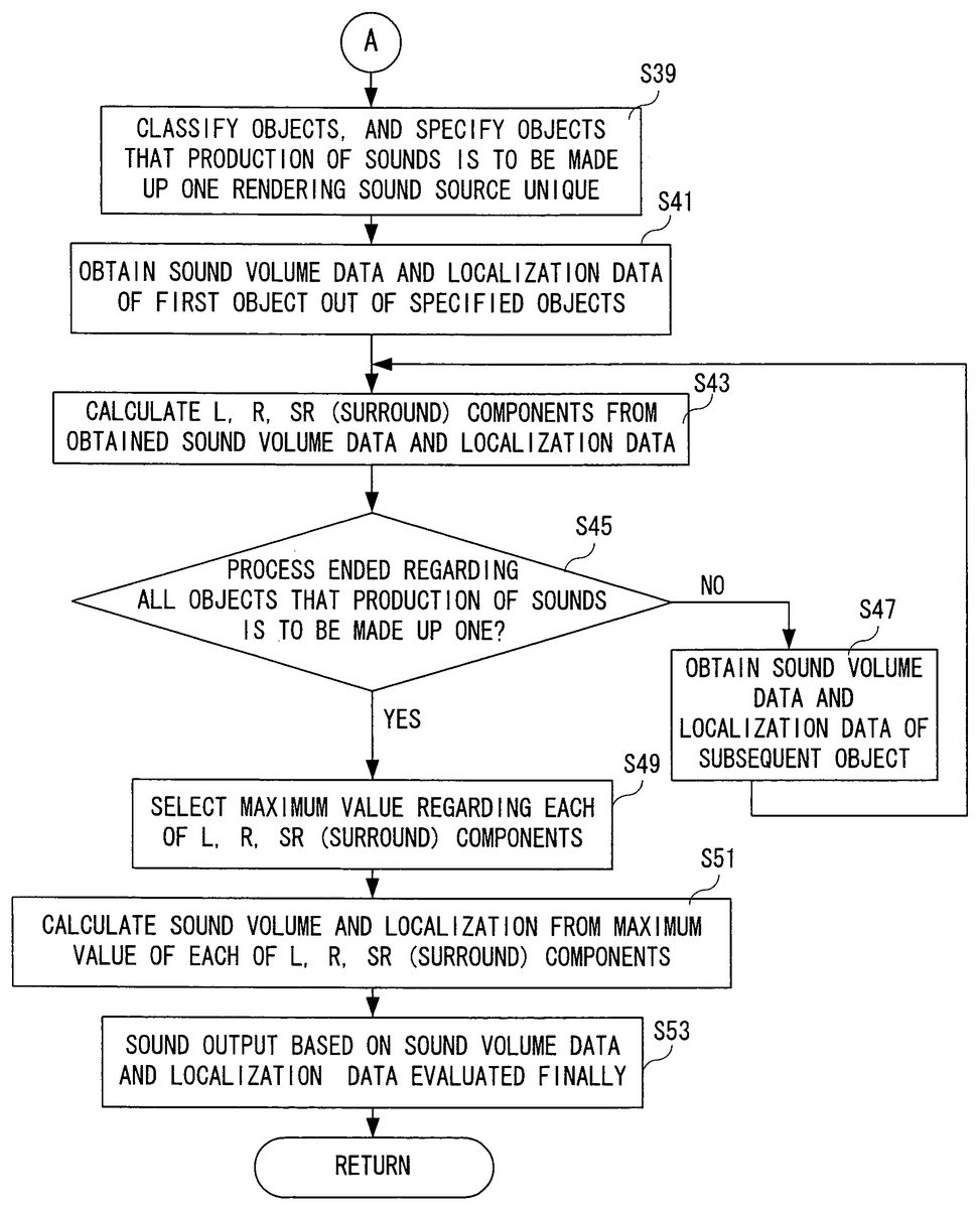
If “NO” in the step S35, that is, unless the calculating process of the sound volume data and the localization data regarding all the objects is ended, the coordinate data of a subsequent object is searched in a step S37, and then, the process returns to the step S31. On the other hand, if “YES” in the step S35, that is, if the calculating process of the sound volume data and the localization data regarding all the objects is ended, in a step S39shown inFIG. 15, the objects are classified so as to specify the objects the sound-productions of the sound sources are to be made up one (bringing the sound-productions of the sound sources into one). That is, in a case that a plurality of the sound objects such as the torch exist, or the sound object such as the river exists, the objects that the sound-productions of the sound sources are brought into one is specified in the step S39.
In a succeeding step S41, regarding a first object included in the classification of the specified objects, the sound volume data and the localization data calculated in the steps S31and S33are obtained. It is noted that the order of obtaining the object is arbitrarily determined by the CPU36. In a succeeding step S43, using the obtained sound volume data and the localization data, the L, R, and SR components are calculated. Next, in a step S45, it is determined whether or not all processes are ended regarding the objects to be brought into one. That is, regarding all the objects included in the group of the objects classified in the step S39, it is determined whether or not the L, R, and SR components are calculated.
If “NO” in the step S45, that is, unless the L, R, and SR components regarding all the objects are ended, a subsequent object is searched in a step S47, and then, the process returns to the step S43. On the other hand, if “YES” in the step S45, that is, if the calculation of the L, R, SR components regarding all the objects is ended, respective maximum values are selected from the L, R and SR components regarding all the objects calculated in a step S49.
In a succeeding step S51, the sound volume and the localization are calculated on the basis of the respective maximum values of the selected L, R, SR components. In other words, one virtual sound object is specified, and the sound volume and the localization of the sound object are calculated. Then, in a step S53, based on the sound volume data and the localization data calculated in the step S51, the sound is output. That is, the CPU36applies to the DSP52an instruction of an output control of the sound, calculates the L, R and SR components from the sound volume data and the localization data, and applies the calculation result to the DSP52. In response thereto, the DSP52reads out the sound waveform data from the SRAM54, and generates the sound data according to the calculation result of the L, R and SR components. Then, the DSP52applies the generated sound data to the audio I/F62. Consequently, the sound signal converted into an analog signal is output from the speaker34a.
It is noted that in a case that a plurality of kinds of the objects to be brought into one exist, depending on the number thereof, the processes of the steps S41to S53are repeated.
It is noted that the sound volume data and the localization data once calculated are brought into being corresponded to the three-dimensional coordinate of the virtual camera (virtual microphone86) in the game world, and stored into the sound output control data storing area76of the main memory40, as described usingFIG. 3. A writing process into the main memory40may be executed by another game process in the step S15shown inFIG. 13, for example. Therefore, after the subsequent time, in a case that the virtual microphone86exists in the same location or position, the sound control process shown inFIG. 14andFIG. 15is not executed, and by referring to the main memory40, the sound regarding a plurality of the sound objects of the same kind or the sound object requiring the sound-production of a plurality of the sound sources, it is possible to easily output by using only the single sound-production of the sound source.
In addition, in this example, the sound produced by a plurality of the sound objects of the same kind are output by the single sound-production of the sound source so that, after obtaining the maximum values of the L, R and SR components, the sound volume data and the localization data are calculated using the same. However, the obtained maximum values may be directly applied (transferred) to the DSP52. This, too, allows to bring into one the sound produced by a plurality of the sound objects of the same kind, thus possible to reduce the number of sound-productions of the sound source to be used.
As shown inFIG. 16, once the rail data process is started, a coordinate list of the object is obtained in a step S61. That is, a plurality of three-dimensional coordinate data are obtained. Then, in a step S63, a point at which the distance from each rail to the origin becomes the shortest, that is, a coordinate of the point closest to the origin is calculated. That is, each rail is substituted to the sound object.
It is noted that in the above game process, at a timing that the position of the player character is updated, the sound control process is executed. However, by operating a button switch of the operating means26of the controller22, for example, at a timing that the viewpoint of the virtual camera of the three-dimensional image is changed, via the camera process (microphone process) and the object rendering process, the sound control process may be also executed.
According to one aspect of this example implementation, the sound of a plurality of the objects of the same kind are output by the single sound-production of the sound source so that it is possible to use less resources of the sound source. That is, it is possible to effectively use the sound source. In addition, the sound source is not deleted according to the priority order, thus not deteriorating the liveliness of the game.
It is noted that in this example, in a case that a plurality of the sound objects of the same kind exist, these sound objects are brought into the single sound-production at the sound source, thus using less sound source. However, even in a case that the sound source is used less, when the number of sound-productions of the usable sound source is exceeded, according to the priority order data (seeFIG. 5) included in the data of the sound object, the sound of the sound object not to be output is determined. However, as described above, the priority order of the sound object that brings the sound-production of the sound source into one is set high, and the sound is always output.
Furthermore, in this example, in a case that the sound object producing the sound of the same kind exists irrespective of the number of sound-productions of the sound source, these are brought into one. However, only in a case that the number of the sound objects exceeds a predetermined number, the same kind of the sound may be brought into one sound-production of the sound source.
Furthermore, in this example, descriptions are only given to the video game apparatus as shown inFIG. 1. However, it is needless to say that the illustrative exemplary non-limiting implementations disclosed herein are applicable to another game apparatus or a portable game machine or a DVD player, and etc., that produce the sound produced by the sound object displayed on the monitor by a sound processor such as the DSP using the sound waveform data.
Still furthermore, in this example, a case of being provided with only right and left speakers, or a case of being further provided with the surround speaker is described. However, two speakers are sufficient if capable of outputting the sound at least in two directions. In addition, four or more speakers may be provided. Furthermore, in a case of calculating the component of the sound volume, as shown in the above embodiment, it is desirable to calculate according to the number of the speakers.
Furthermore, in this example, only the torch, the river and, the wave sound objects are described. However, sound objects are not necessary limited to these example alone.
Although the present invention illustrative exemplarv non-limiting implementations disclosed herein have been described and illustrated in detail, it is clearly understood that the same is by way of illustration and example only and is not to be taken by way of limitation, the spirit and scope of applicants' invention being limited only by the terms of the appended claims.
Claims
- In a computer controlled game apparatus which includes a mechanism for inputting game operating information by a human player, a memory for storing data for displaying objects constituting a game image, an image display control for displaying the game image including at least two of said objects based on said operating information, said at least two objects constituting said game image each being a sound object that produces a sound, a waveform data storage memory for storing one or more sets of waveform data corresponding to one or more sounds produced by one or more sound objects, a sound producing position storage memory for storing sound producing position data indicating a producing position of the sound for each said sound object, and a microphone data storage memory for storing microphone data including sound collecting position data indicating a position at which a sound is to be collected during game play, a computer game sound control program product embodied on a computer-readable medium for distribution and/or storage on a computer controlled game apparatus, comprising: program instruction means for computing sound volume data of sounds respectively produced by said sound objects based on both said sound producing position data and said microphone data;program instruction means for dividing the sound volume data into sound volume component data corresponding to at least two directions;program instruction means for classifying, out of all said sound objects, the sound objects which produce an identical sound;and program instruction means for extracting a maximum sound volume component of said component data corresponding to two directions associated with a sound object producing said same sound and outputting the sound based on the waveform data of the object and said maximum sound volume component data of each component.
- A computer game sound control program product according to claim 1 , further comprising: sound producing program instructions for computing localization data and the sound volume data of the sound to be output based on said maximum sound volume component data.
- A computer game sound control program product according to claim 1 , wherein said microphone data further includes sound-collection direction data indicating a direction from which the sound is to be collected during the game, and said program instruction means for dividing sound volume data divides, based on said sound producing position data and said sound-collection direction data, the sound volume data of a sound object into right sound volume data, left sound volume data, and surround sound volume data.
- A computer game sound control program product according to claim 3 , further comprising object sound localization calculation instruction means for computing a localization of one sound based on the sounds of at least said two sound objects from said sound producing position data and said microphone data;wherein said program instruction means for dividing sound volume data divides said sound volume data of sound object into the right sound volume data, the left sound volume data, and the surround sound volume data based on the localization of the sound calculated by said object sound localization calculating program.
- A computer game sound control program product according to claim 3 , wherein said sound producing position data includes position data of a sound object represented by one coordinate data, and position data of the sound object having rail data defined by at least two coordinate data;further comprising near coordinate calculating program instruction means for calculating coordinate data existing on a line connecting the coordinates indicating said rail data and most close to said sound collecting position data regarding the sound object having said rail data;wherein said program instruction means for computing sound volume data computes the sound volume data of the sound object on the basis of the coordinate data computed by said near coordinate calculating program instruction means and said sound volume position data when computing the sound volume data of the sound object having said rail data, said program instruction means for dividing sound volume component data divides the sound volume data on the basis of the coordinate data computed by said near coordinate calculating program instruction means and said sound collecting position data, into the right sound volume data, the left sound volume data, and the surround sound volume data.
- In a game apparatus that comprises a CPU, a mechanism for inputting game operating information, a memory for storing data for displaying objects constituting a game image, said game image comprising one or more game objects based on said operating information wherein at least two of said game objects constituting said game image are sound objects that produce a sound during game play, a memory for storing waveform data corresponding to sounds produced by one or more sound objects a memory for storing sound producing position data indicating a producing position of sound for a sound object, and a memory for storing microphone data comprising sound collecting position data for indicating a position at which a sound is to be collected during game play, a method for generating game sounds, comprising the steps performed by said CPU, of: (a) computing sound volume data of sounds respectively generated by said sound objects on the basis of both said sound producing position data and said microphone data;(b) dividing the sound volume data computed by said step (a) into said sound volume component data corresponding to at least two different directions;(c) identifying, out of all said sound objects, objects producing the same sound;and (d) extracting a maximum sound volume component data for each component of said at least two directions associated with each said object producing the same sound, and outputting the sound based on the waveform data corresponding to said objects producing the game sound and the maximum sound volume component data of said each component.
- A method for generating game sound according to claim 6 , wherein said extracting step includes computing localization data and sound volume data of the sound output based on said maximum sound volume component data.
- A method for generating game sound according to claim 6 , wherein said microphone data further includes sound-collection direction data indicating a direction at which the sound is collected during game play, said dividing step divides the sound volume data of said sound object volume from said sound producing position data and said sound-collection direction data into right sound volume data, left sound volume data, and surround sound volume data.
- A method for generating game sound according to claim 8 , further comprising: (e) computing a localization of one sound from said sound producing position data and said microphone data based on the sound of said sound objects;wherein said dividing step divides said sound volume data of said sound object volume based on a computed localization into the right sound volume data, the left sound volume data, and the surround sound volume data.
- A method for generating game sound according to claim 8 , wherein said sound producing position data includes rail data sound source position data represented by point sound source position data represented by one coordinate data, and the rail data defined by at least two coordinate data;further comprising a step of: (f) computing coordinate data of a location most close to said sound collecting position data regarding the sound object having said rail data existing on a line connecting coordinates indicating said rail data;wherein said computing step computes the sound volume data of the sound object from computed coordinate data and said sound volume position data when computing the sound volume data of a sound object having said rail data, and said dividing step divides the sound volume data into right sound volume data, left sound volume data, and surround sound volume data, respectively, on the basis of coordinate data calculated by said near coordinate calculation instructions and said sound collecting position data.
- A video game apparatus capable of displaying a plurality of game objects and producing sounds associated with a plurality of sound generating objects, comprising: a storage memory for storing sound waveform data corresponding to sounds associated with a plurality of sound generating objects;a storage memory for storing sound producing position data indicating a producing position of the sound for each said sound generating object;a storage memory for storing microphone data including sound collecting position data for indicating one or more positions at which sound is collected during game play;a sound volume calculator wherein sound volume data for one or more sound generating objects is computed based on said sound producing position data and said microphone data;a sound volume component divider wherein the sound volume data computed by said sound volume data calculator is resolved into sound volume component data corresponding to two or more directions;a sound output mechanism which outputs audio sounds on said waveform data and said sound volume component data;a sound generating object classify or that identifies, out of all said sound objects, which sound generating objects produce the same sound;and a sound volume component extractor which resolves a maximum sound volume component data for each component of said two or more directions associated with each object that produces said same sound and which provides the waveform data of the sound generating object and the maximum sound volume component data of said each component to the sound output mechanism.
- A video game apparatus according to claim 11 , wherein said sound output mechanism includes a sound volume calculator for computing the localization data and the sound volume data of the sound output based on said maximum sound volume component data.
- A video game apparatus according to claim 11 , wherein said microphone data further includes the sound collecting direction data indicating a direction at which the sound is to be collected during game play, said sound volume component divider divides the sound volume data of said sound object from said sound producing position data and said sound-collection direction data into right sound volume data, left sound volume data, and surround sound volume data.
- A video game apparatus according to claim 13 , further comprising an object sound localizer which computes a localization of a sound based on the sound of two or more sound objects from said sound producing position data and said microphone data;wherein said sound volume component divider divides said sound volume data of said sound object based on a computed localization of the sound into the right sound volume data, the left sound volume data, and the surround sound volume data.
- A video game apparatus according to claim 13 , wherein said sound producing position data includes position data of a sound object having rail data represented by sound object position data represented by single coordinate data and rail data represented by multiple coordinate data;further comprising a near coordinate calculating mechanism for computing the coordinate data existing on a line connecting coordinates indicating said rail data, and in a position most close to said sound collecting position data stored in said microphone data storing means regarding the sound object having said rail data;wherein said sound volume data calculator computes the sound volume data of the sound object on the basis of the coordinate data computed by said near coordinate calculator and said sound volume position data when computing the sound volume data of the sound object having said rail data, said sound volume component divider divides the sound volume data on the basis of the coordinate data computed by said near coordinate calculator and said sound collecting position data into the right sound volume data, the left sound volume data, and the surround sound volume data.
- A method for producing sounds associated with a plurality of displayable objects in a video game apparatus, comprising: storing sound waveforms data;storing sound production position data;storing sound collection position data;associating sound waveform data with one or more displayable objects;computing sound volume data for two or more sound generating displayable objects based on the sound producing position data and the sound collection position data;resolving sound volume data for said two or more sound generating displayable objects into sound component data comprising two or more directional components;and outputting sound data for two or more of said displayable objects based on waveform data associated with each said displayable object and one or more directional components of computed sound volume data of said displayable objects;wherein said video game apparatus includes and/or accepts memory storage devices for storing sound related data and a processor for computing and resolving sound volume data.
- The method of claim 16 further comprising: identifying sound generating objects, out of said plurality of sound generating objects, that are associated with a same sound waveform;selecting volume component data corresponding to the maximum directional components of said sound volume component of each of said plurality of sound generating object;and associating selected maximum sound volume component with corresponding waveform data for each of said plurality of objects.
Disclaimer: Data collected from the USPTO and may be malformed, incomplete, and/or otherwise inaccurate.