U.S. Pat. No. 7,330,769
PARAMETERIZED INTERACTIVE CONTROL OF MULTIPLE WAVE TABLE SOUND GENERATION FOR VIDEO GAMES AND OTHER APPLICATIONS
AssigneeNintendo Software Technology Corporation
Issue DateMay 15, 2002
Illustrative Figure
Abstract
In the context of a video game, multimedia presentation or other application, multiple sound sample files are read out simultaneously and mixed together. The volumes and/or pitches of the wave tables are parameterized to allow a single parameter (e.g., power, intensity, etc.) to simultaneously control the multiple read out processes. The control parameter may be, for example, responsive to a user-manipulable control, such as a joystick. Sound effects produced using this technique are rich and interesting, and the user feels as if he or she is directly controlling the effect.
Description
DETAILED DESCRIPTION OF PRESENTLY PREFERRED EXAMPLE EMBODIMENTS FIG. 1shows an example block diagram of a multimedia system10such as a home video game system with which the present invention may be used or employed. In the example embodiment, system10includes a user-manipulable control12such as a continuously-variable analog joystick. The user-manipulable control12controls graphics generation via a graphics engine14as well as sound effect generation via a sound effect generator16. The graphics generator14produces interesting 2D or 3D graphics for display on a display device18such as home color television set or other display device. The sound effects generator16provides interesting sound effects for reproduction by one or more loudspeakers20. In one example embodiment, the graphics generator14and sound effects generator16may be implemented in hardware and/or software on a personal computer and/or in a home video game platform such as the NINTENDO 64 or NINTENDO GAMECUBE system. Basic sound generation and/or synthesis using these types of platforms is well known. See, for example, U.S. Pat. No. 6,166,748 to Van Hook et al, entitled “INTERFACE FOR A HIGH PERFORMANCE LOW COST VIDEO GAME SYSTEM WITH COPROCESSOR PROVIDING HIGH SPEED EFFICIENT 3D GRAPHICS AND DIGITAL AUDIO SIGNAL PROCESSING”, and U.S. patent application Ser. No. 09/722,667 of CHENG et al., entitled “METHOD AND APPARATUS FOR PRE-CACHING DATA IN AUDIO MEMORY” filed Nov. 28, 2000, both incorporated herein by reference. FIG. 2shows a high level block diagram of the steps used to create a sound model in accordance with the instant invention. The sound model is designed to model a sonic event, condition or environment that could exist in the multimedia application. The sound model defines the information necessary for determining how the sound(s) for the sonic event are to be adjusted based on the parameter(s). Thus, the sound model includes one or more waveforms representing sounds, one or more parameters, and, for ...
DETAILED DESCRIPTION OF PRESENTLY PREFERRED EXAMPLE EMBODIMENTS
FIG. 1shows an example block diagram of a multimedia system10such as a home video game system with which the present invention may be used or employed. In the example embodiment, system10includes a user-manipulable control12such as a continuously-variable analog joystick. The user-manipulable control12controls graphics generation via a graphics engine14as well as sound effect generation via a sound effect generator16. The graphics generator14produces interesting 2D or 3D graphics for display on a display device18such as home color television set or other display device. The sound effects generator16provides interesting sound effects for reproduction by one or more loudspeakers20.
In one example embodiment, the graphics generator14and sound effects generator16may be implemented in hardware and/or software on a personal computer and/or in a home video game platform such as the NINTENDO 64 or NINTENDO GAMECUBE system. Basic sound generation and/or synthesis using these types of platforms is well known. See, for example, U.S. Pat. No. 6,166,748 to Van Hook et al, entitled “INTERFACE FOR A HIGH PERFORMANCE LOW COST VIDEO GAME SYSTEM WITH COPROCESSOR PROVIDING HIGH SPEED EFFICIENT 3D GRAPHICS AND DIGITAL AUDIO SIGNAL PROCESSING”, and U.S. patent application Ser. No. 09/722,667 of CHENG et al., entitled “METHOD AND APPARATUS FOR PRE-CACHING DATA IN AUDIO MEMORY” filed Nov. 28, 2000, both incorporated herein by reference.
FIG. 2shows a high level block diagram of the steps used to create a sound model in accordance with the instant invention. The sound model is designed to model a sonic event, condition or environment that could exist in the multimedia application. The sound model defines the information necessary for determining how the sound(s) for the sonic event are to be adjusted based on the parameter(s). Thus, the sound model includes one or more waveforms representing sounds, one or more parameters, and, for each waveform and each parameter, a corresponding pitch adjustment function and/or volume adjustment function. The pitch and volume adjustment functions are referred to herein as a pitch envelope and a volume envelope, respectively. Visually speaking, a pitch envelope provide a graph showing the change in pitch for a waveform as a function of a parameter, and the volume envelope provides a graph showing the change in volume for a waveform as a function of a parameter. In the preferred embodiment, the sound model provides a collection of waveforms, whose pitch and volume are adjusted based on the envelopes for any number of parameters.
As shown inFIG. 2, the first step in creating a sound model is to define at least one waveform representing sound (step22). The next step involves defining one or more parameters that are dependent on the application in which the sonic event is to occur, such as one or more parameters that depend on a user's operation of a joystick or other control member during play of a video game (step24). For example, if the application is a car racing videogame, a defined parameter could be the amount of power that the user gives the virtual car as a result of manipulation of the joystick on the game controller. Another parameter could be the speed at which the virtual car is moving in the game or the angle at which the user causes the virtual car to hit another car or other obstacle. Any suitable parameter, as well as any number of different parameters, can be defined by the person creating the sound model.
Once the waveforms and the parameters are defined for the sound model, the next step is to define, for each waveform, a pitch envelope for each parameter (step26). This involves defining a functional relationship between the pitch of each waveform and the value of each parameter (see, for example,FIGS. 6 and 7). The next step is to define, for each waveform, a volume envelope for each parameter (step28). The volume envelopes define the functional relationship between the volume of each waveform and the value of each parameter (see, for example,FIGS. 3,4, and5). While it is preferred to define a pitch and volume envelope for each waveform and each parameter, other embodiments may be used wherein only certain waveforms are adjusted by certain parameters, and/or certain parameters only effect the volume or pitch of one or more waveforms in the model. Once defined, the waveform(s) and pitch and volume envelopes for each parameter are stored as a sound model for the sonic event. Additional sound models can also be created and stored in order to model a variety of virtual sonic events that may arise or be present in a gaming or other application.
FIG. 3shows an example of a volume envelope30for a waveform representing a collision sound based on the parameter “angle”. This angle parameter represents the angle at which two objects collide in a gaming application, such as the angle at which one virtual racing car hits another virtual racing car. As shown inFIG. 3, the volume increases substantially linearly from a minimum value of about 0 to a maximum value of 1 as the collision angle increases from a very slight angle (close to 0—a glancing blow)) to a 90 degree angle (a head-on collision). In this example, an angle of 85 degrees would result in a volume of 0.85. Thus, the volume of the waveform is parameterized by the angle parameter. The volume for this waveform in the sound model is then determined based on the current value of the angle parameter.
FIG. 4shows an example of a volume envelope40for a waveform based on the parameter “speed”. This speed parameter represents the speed at which an object, such as a virtual racing car is moving. As shown inFIG. 4, the volume increases substantially linearly from no speed to a speed of about 187 mph, and then increases at a progressively slower rate to the maximum volume of 1 as the vehicle increases its speed from 187 to 300 mph. In this example, the speed of 100 will result in a volume of 0.5.
The volume envelopes ofFIGS. 3 and 4can be used in, for example, a sound model for a car hitting a wall having a first parameter “angle” and a second parameter “speed.” In this example, if the car hits the wall at 100 mph and at an angle of 0.85, the final waveform could be determined by multiplying or otherwise combining the parameterized volumes (e.g., 0.5×0.85=0.425). This example assumes a constant pitch. However, this exemplary car accident model could be further enhanced by the addition of pitch envelopes for the parameters, as well as adding several additional waveforms overlapping each other in volume and/or pitch, thereby resulting in a complex and dynamic sound model. Additional parameters could also be added to increase the complexity and depth of the sound. For example, a third parameter representing the thickness of the surface the car hits could be added to adjust the sound accordingly, such as by decreasing the pitch as the thickness decreases to give a more “hollow” sound to the collision. Thus, in accordance with the preferred embodiment of the invention, the resulting output for each waveform that is contained in the sound model is based on the adjustment to pitch and volume that the first parameters envelope performs on the sound, subsequently modulated by the adjustment to pitch and volume that the second parameter's envelope performs on the sound, and so on.
FIG. 5shows a pair of exemplary volume envelopes (42,44) for two waveforms based on the parameter “power.”FIG. 6shows a pair of exemplary pitch envelopes (46,48) for two waveforms based on the parameter “power.” The envelopes ofFIGS. 5 and 6could be used to define a sound model having four waveforms, each adjusted in volume and pitch by the parameter “power”.FIG. 7shows additional exemplary pitch envelopes (702,704,706,708,710and712) for the parameter “power.”
FIG. 8shows a high level flow chart of the preferred steps performed in accordance with the invention for generating sound effects using sound models of the present invention. The process begins by starting the application, such as beginning gameplay on a videogame platform (step800). If there are several sound models available for the application, then a first step involves selecting the appropriate sound model for the current condition of the game (step802). The system then obtains the current value for each parameter in the sound model based on the current gameplay condition (step804), such as how fast the user is causing a virtual racing car to travel and how much power he/she is giving to the vehicle. Then, for each waveform in the sound model, the pitch and volume is adjusted based on the pitch and volume envelopes in the sound model using the current value of each parameter (step806). The adjusted waveforms are then mixed together to obtain the final sound for the current gameplay condition (step808). The final sound is then output through the audio system (step810). The process is then repeated using the same or different sound model (step812) and using the next current value of the parameters. In this way a continuous, complex and dynamic sound effects can be generated for the videogame (or any other suitable application).
FIG. 9shows a more detailed block diagram of an exemplary sound effects engine16provided by the preferred embodiment of the present invention. In this example, the user manipulable control12(e.g. joystick) generates a control parameter P used to control the read out of a plurality of digitally stored sound wave tables50(defining the waveforms for a sound model). Storage of digital sound samples in wave tables50is well known. In this particular embodiment, a user-controlled parameter P is used to vary the pitch of the wave table read out via a pitch control52and/or the amplitude of the wave table read out via volume control54. Different or more complex wave table read out variations are also or alternatively possible, but the inventors have found that great flexibility can be provided by varying the pitch and/or volume envelopes of wave tables50based on one or more parameters. The resulting simultaneous streams of digital samples S1, S2, . . . , Sn read out from wave tables50are mixed together by a mixer56before being applied to a loudspeaker58via an analog-to-digital converter for conversion into audible sound. In this example embodiment, the transfer functions (or envelopes) of the various pitch control blocks52and volume control blocks54are different, and these transfer functions, VFCN, PFCNare customized with respect to the input parameter P. For example, seeFIG. 7representing read out of multiple wave tables50at variable pitches controlled by a “power” parameter P. As shown in illustrativeFIG. 7, for a power factor set to a minimal level, the pitch control52(1) associated with the first wave table50(1) read out may be set to 200% whereas the pitch control52(2) associated with the read out of a further wave table50(2) may be set to 100%. As the power parameter P is increased (e.g., by a user pushing analog joystick12forward), the pitch control block52(1) may sharply increase the pitch applied to the read out of wave table50(1) to 350% or so before providing a relatively linear decrease to 0% (see curve702). In contrast, for the same operation of joystick12, the pitch control block52(2) associated with read out of wave table50(2) may increase the pitch from 100% to 200% with a maximum roughly corresponding to the same maximum of curve702and then maintaining the pitch at an approximately constant value based on further increases in the power parameter P (see curve704). As also shown inFIG. 7, additional characteristic pitch transfer functions PFCN(or envelopes) associated with further wave tables50(n) can be used to provide additional wave table read out pitch control based on the same parameter P in order to provide an even more complex and rich sound effect. In a similar manner, the volume control blocks54associated with the various plurality of wave table52read outs can provide different transfer functions (or envelopes) based upon a common parameter P. Further streams of digital samples may be provided by other pitch controls and volume controls based on the same or other wave tables using other parameters (P2. . . Pn) (as indicated by block16′).
Many different complex sound effects can be created through providing such customized transfer functions for different wave table50read outs. For example, the inventors have successfully simulated the sound of a racing car engine increasing in engine speed from idle to racing speeds. The inventors have also successfully simulated the sound of rain changing from light rain to very heavy rain using these techniques. An almost infinite number of variations in wave tables and associated transfer functions controlling wave table read out and/or modification can be used to provide any desired sound effect.
As will be understood, the various volume control and pitch control transfer functions Vfcn(1) . . . Vfcn(n) and Pfcn(1) . . . Pfcn(n) may be specified by equations, through lookup tables, by multiplication or other combination with reference digital strings, or via any other convenient method.
The example embodiment parameterized the volume control blocks54and pitch control blocks52with a parameter P responsive to user manipulation of control12. In other embodiments, parameter P can be supplied by some other source (e.g., execution of a video game) or by a combination of user interactivity and non-user interactivity. In other words, the parameters used in accordance with the instant invention can be directly or indirectly related to user interactivity.
While the embodiment has been described above as “simultaneously” reading out the contents of multiple wave tables50, it will be understood by those or ordinary skill in the art that truly simultaneous read out is not generally possible in a single-processor sound generation system. In such single-processor systems, for example, it may be that one wave table50(1) may be processed first and then a second wave table50(2) may then be processed, with the results of the two processes subsequently combined by a mixer56before application to loudspeaker58. By the term “simultaneous”, we do not intend to restrict our invention to true simultaneous operations, but rather intend to encompass substantially real-time concurrent processing of multiple wave tables so that a human ear hears the results of multiple wave table processing as part of the same overall effect.
EXAMPLE ILLUSTRATIVE IMPLEMENTATION
FIGS. 10A and 10Bshow an example interactive 3D computer graphics system50. System50can be used to play interactive 3D video games with interesting displays and sound effects provided by a preferred embodiment of this invention. System50can also be used for a variety of other applications.
In this example, system50is capable of processing, interactively in real time, a digital representation or model of a three-dimensional world. System50can display some or the entire world from any arbitrary viewpoint. For example, system50can interactively change the viewpoint in response to real time inputs from handheld controllers52a,52bor other input devices. This allows the game player to see the world through the eyes of someone within or outside of the world. System50can be used for applications that do not require real time 3D interactive display (e.g., 2D display generation and/or non-interactive display), but the capability of displaying quality 3D images very quickly can be used to create very realistic and exciting gameplay or other graphical interactions.
To play a videogame or other application using system50, the user first connects a main unit54to his or her color television set56or other display device by connecting a cable58between the two. Main unit54produces both video signals and audio signals for controlling color television set56. The video signals are what controls the images displayed on the television screen59, and the audio signals are played back as sound through television stereo loudspeakers61L,61R. The sounds played are generated using the sound model and sound generation technique of the instant invention.
The user also needs to connect main unit54to a power source. This power source may be a conventional AC adapter (not shown) that plugs into a standard home electrical wall socket and converts the house current into a lower DC voltage signal suitable for powering the main unit54. Batteries could be used in other implementations. The user may use hand controllers52a,52bto control main unit54. Controls60can be used, for example, to specify the direction (up or down, left or right, closer or further away) that a character displayed on television56should move within a 3D world. Controls60also provide input for other applications (e.g., menu selection, pointer/cursor control, etc.). Controllers52can take a variety of forms. In this example, controllers52shown each include controls60such as joysticks, push buttons and/or directional switches. Controllers52may be connected to main unit54by cables or wirelessly via electromagnetic (e.g., radio or infrared) waves. The parameters for use in connection with the sound models of the present invention can be obtained from the controllers52.
To play an application such as a game, the user selects an appropriate storage medium62storing the video game or other application he or she wants to play, and inserts that storage medium into a slot64in main unit54. Storage medium62may, for example, be a specially encoded and/or encrypted optical and/or magnetic disk. The user may operate a power switch66to turn on main unit54and cause the main unit to begin running the video game or other application based on the software stored in the storage medium62. The user may operate controllers52to provide inputs to main unit54. For example, operating a control60may cause the game or other application to start. Moving other controls60can cause animated characters to move in different directions or change the user's point of view in a 3D world. Depending upon the particular software stored within the storage medium62, the various controls60on the controller52can perform different functions at different times.
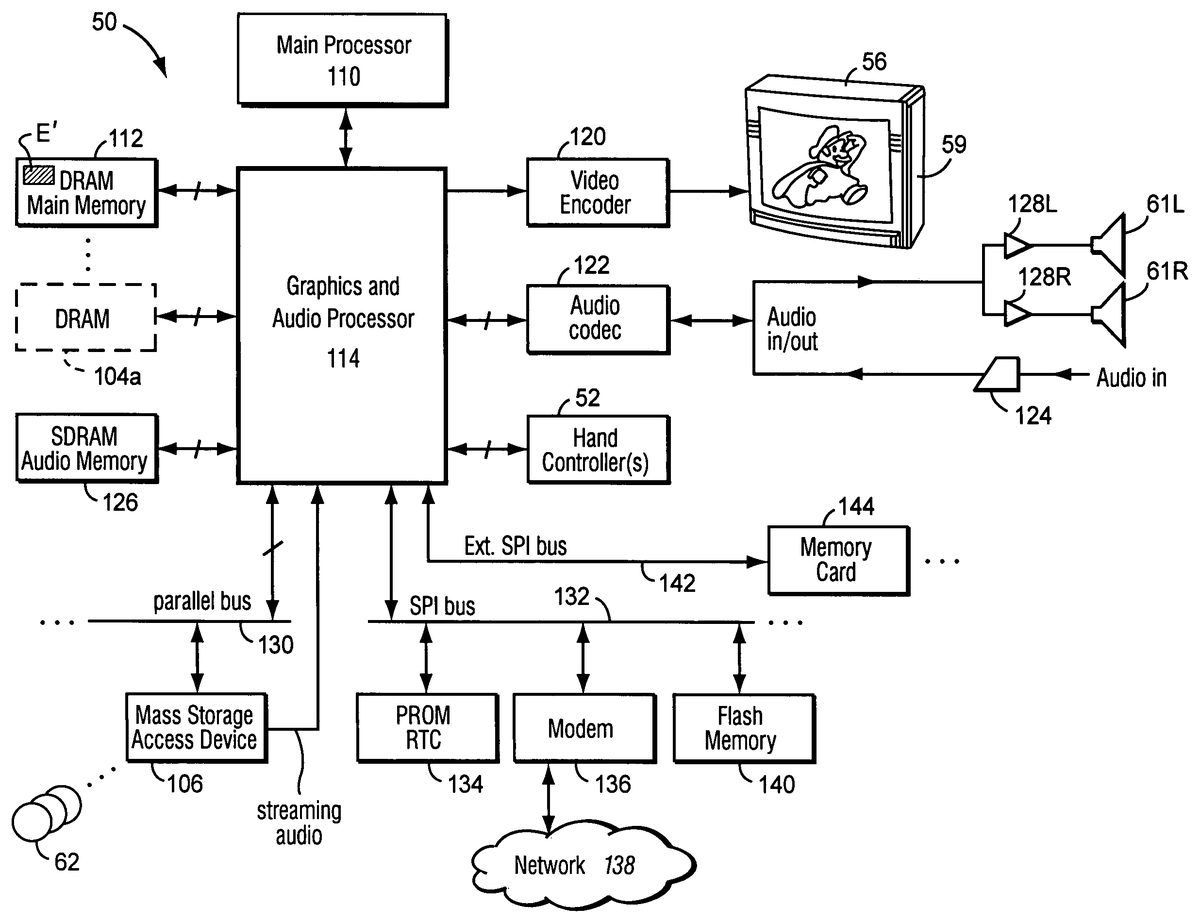
As also shown inFIGS. 10A and 10B, mass storage device62stores, among other things, a videogame program E that enables an interactive game to be played using the system50and incorporates the sound generation feature of the instant invention. The program E in the preferred embodiment makes use of various components of system50shown inFIG. 10Bincluding:a main processor (CPU)110,a main memory112, anda graphics and audio processor114.
In this example, main processor110(e.g., an enhanced IBM Power PC750) receives inputs from handheld controllers52(and/or other input devices) via graphics and audio processor114. Main processor110interactively responds to user inputs, and executes a video game or other program supplied, for example, by external storage media62via a mass storage access device106such as an optical disk drive. As one example, in the context of video gameplay, main processor110can perform collision detection and animation processing in addition to a variety of interactive and control functions.
In this example, main processor110generates 3D graphics and audio commands and sends them to graphics and audio processor114. The graphics and audio processor114processes these commands to generate interesting visual images on display59and interesting stereo sound on stereo loudspeakers61R,61L or other suitable sound-generating devices. Main processor110and graphics and audio processor114also perform functions to support and implement the preferred embodiment program E based on instructions and data E′ relating to the program that is stored in DRAM main memory112and mass storage device62.
As further shown inFIG. 10B, example system50includes a video encoder120that receives image signals from graphics and audio processor114and converts the image signals into analog and/or digital video signals suitable for display on a standard display device such as a computer monitor or home color television set56. System50also includes an audio codec (compressor/decompressor)122that compresses and decompresses digitized audio signals and may also convert between digital and analog audio signaling formats as needed. Audio codec122can receive audio inputs via a buffer124and provide them to graphics and audio processor114for processing (e.g., mixing with other audio signals the processor generates and/or receives via a streaming audio output of mass storage access device106). Graphics and audio processor114in this example can store audio related information in an audio memory126that is available for audio tasks. Graphics and audio processor114provides the resulting audio output signals to audio codec122for decompression and conversion to analog signals (e.g., via buffer amplifiers128L,128R) so they can be reproduced by loudspeakers61L,61R.
Graphics and audio processor114has the ability to communicate with various additional devices that may be present within system50. For example, a parallel digital bus130may be used to communicate with mass storage access device106and/or other components. A serial peripheral bus132may communicate with a variety of peripheral or other devices including, for example:a programmable read-only memory and/or real time clock134,a modem136or other networking interface (which may in turn connect system50to a telecommunications network138such as the Internet or other digital network from/to which program instructions and/or data can be downloaded or uploaded), andflash memory140.
A further external serial bus142may be used to communicate with additional expansion memory144(e.g., a memory card) or other devices. Connectors may be used to connect various devices to busses130,132,142.
While the invention has been described in connection with its most preferred embodiments, other variations are possible. For example, while the invention has been described in connection with a video game or other multimedia presentation including both graphics and sound, the invention could alternatively be used in an audio-only context without graphics. Additionally, while the invention has been described in connection with the embodiment used to generate sound effects, other types of sounds (e.g., music or other audible information) could be generated. Accordingly, the invention is not to be limited to the disclosed exemplary embodiments, but on the contrary, is intended to cover all variations and equivalents within the scope of the claims.
Claims
- A method of creating a sound model for use in dynamically generating sound effects during execution of a computerized multimedia application in which a user provides input that affects both video and sound produced by the multimedia application, said method comprising: defining a plurality of waveforms representing various different sounds that may be generated simultaneously by a single sound generating object during execution of the interactive multimedia application;defining a parameter that relates to the sound generating object and is variable during execution of the multimedia application;defining an adjustment function, for each of the plurality of waveforms, between the parameter and at least one characteristic of each of the plurality of waveforms, wherein each adjustment function provides a functional relationship between a value of the parameter and a value of the characteristic of the respective waveform, and further wherein the plurality of waveforms, the parameter and the adjustment functions define the sound model;displaying a graph showing the adjustment function for each of the plurality of waveforms, the graph visually depicting during game development by a game designer one or more relationships existing between each of the adjustment functions;storing the sound model for use in dynamically generating sound effects during execution of the multimedia application;and using the stored sound model to dynamically generate sound effects during execution of the multimedia application.
- A method of creating a sound model as in claim 1 , wherein defining a parameter includes defining a parameter that varies based at least in part on user interactivity with the multimedia application.
- A method of creating a sound model as in claim 1 , wherein the characteristic of the waveform is volume of the waveform, and defining an adjustment function includes defining a volume adjustment function.
- A method of creating a sound model as in claim 1 , wherein the characteristic of the waveform is pitch of the waveform, and defining an adjustment function includes defining a pitch adjustment function.
- A method of creating a sound model as in claim 1 , wherein the parameter is a non-time based parameter.
- A method of creating a sound model as in claim 1 , further including defining a plurality of different parameters, each of which relates to the sound generating object and is variable during execution of the multimedia application, and defining a plurality of adjustment functions, for each of the plurality of waveforms, that respectively define how a characteristic of the waveforms varies with respect to each of the parameters.
- A method of creating a sound model as in claim 6 , wherein each of the plurality of different parameters varies based at least in part on user interactivity with the multimedia application.
- A method of creating a sound model as in claim 6 , wherein the characteristic of the waveform is volume of the waveform, and the plurality of adjustment functions are volume adjustment functions.
- A method of creating a sound model as in claim 6 , wherein the characteristic of the waveform is pitch of the waveform, and the plurality of adjustment functions are pitch adjustment functions.
- A method of creating a sound model as in claim 6 , wherein the parameters are non-time based parameters.
- A method of creating a sound model as in claim 1 , wherein the sound model models a sonic event that relates to the sound generating object and may occur in the interactive multimedia application.
- A method of creating a sound model as in claim 1 , wherein the sound model models a sonic condition that may exist in the interactive multimedia application.
- A method of creating a sound model as in claim 1 , wherein the sound model models a sonic environment that may exist in the interactive multimedia application.
- A method of creating a sound model for dynamically generating sound effects during execution of a computerized multimedia application in which a user provides input that affects both video and sound produced by the multimedia application, said method comprising: defining a plurality of waveforms representing various different sounds that may be generated simultaneously by a single sound generating object during execution of the interactive multimedia application;defining a parameter that relates to the sound generating object and is variable during execution of the multimedia application;defining an adjustment function, for each of the plurality of waveforms, between the parameter and at least one characteristic of each of the plurality of waveforms, wherein each adjustment function provides a functional relationship between a value of the parameter and a value of the characteristic of the respective waveform, and further wherein the plurality of waveforms, the parameter and the adjustment functions define the sound model;displaying a graph showing the adjustment function for each of the plurality of waveforms, the graph visually depicting during game development by a game designer one or more relationships existing between each of the adjustment functions;storing the sound model for use in dynamically generating sound effects during execution of the multimedia application;and using the stored sound model to dynamically generate sound effects during execution of the multimedia application by determining a current value of the parameter based on a current application condition, adjusting the plurality of waveforms using the current value of the parameter and the adjustment functions, and outputting sound based at least in part on the plurality of adjusted waveforms.
- A method of creating a sound model as in claim 14 , wherein defining a parameter includes defining a parameter that varies based at least in part on user interactivity with the multimedia application.
- A method of creating a sound model as in claim 14 , wherein the characteristic of the waveform is volume of the waveform, and defining an adjustment function includes defining a volume adjustment function.
- A method of creating a sound model as in claim 14 , wherein the characteristic of the waveform is pitch of the waveform, and defining an adjustment function includes defining a pitch adjustment function.
- A method of creating a sound model as in claim 14 , wherein the parameter is a non-time based parameter.
Disclaimer: Data collected from the USPTO and may be malformed, incomplete, and/or otherwise inaccurate.