U.S. Pat. No. 7,326,117
NETWORKED VIDEO GAME SYSTEMS
Issue DateSeptember 22, 2003
Illustrative Figure
Abstract
Video game systems for multiple-player games may exchange synchronizing data through the Internet or other data transmission link. These hidden status data records keep the video game systems synchronized with each other whenever different players are making use of a virtual game doorway or other shared passageway.
Description
DETAILED DESCRIPTION OF EXEMPLARY EMBODIMENT FIG. 1illustrates a preferred embodiment of a multi-player game system that has at least two video game consoles42sending video signals to corresponding television devices11for display as motion pictures. Each video game system42is manually controlled by at least one portable game system44and47being operated as a controller or controllers, in this example. Each game player10and12controls a different player character in the same multi-player game, typically a role playing game (RPG) shared by a small group of friends. All of the video game systems42used by each group of friends execute the same game software during a game session, in this example. The same group of friends may use other game titles during different sessions. Other groups of friends may be using different game software titles simultaneously in separate sessions. Each of the video game systems42transmit status data records78(seeFIG. 13) through the Internet or other communications network121to a messaging server120which forwards the status data records78to other video game systems42in each session. Messaging server120operates like a prior-art instant messaging server that shares each natural language message with several friends in each “buddy list” as described in U.S. Pat. No. 6,539,421, except that in theFIG. 13examples, status data records78contain mostly digital codes and numbers that need not be readable by game players and hence would typically not be displayed as instant messages. Status data records78are sent to the other video game systems42to be processed in each session to keep the systems synchronized so that each video game system42can display any character or object in a simulated game world from variable points of view at any time during each session. Each player's television11displays his/her player character as usual, but other characters, objects, maps, scores, etc. are displayed on a portable game system44,47, in this example. FIG. 2illustrates an embodiment similar to the ...
DETAILED DESCRIPTION OF EXEMPLARY EMBODIMENT
FIG. 1illustrates a preferred embodiment of a multi-player game system that has at least two video game consoles42sending video signals to corresponding television devices11for display as motion pictures. Each video game system42is manually controlled by at least one portable game system44and47being operated as a controller or controllers, in this example. Each game player10and12controls a different player character in the same multi-player game, typically a role playing game (RPG) shared by a small group of friends.
All of the video game systems42used by each group of friends execute the same game software during a game session, in this example. The same group of friends may use other game titles during different sessions. Other groups of friends may be using different game software titles simultaneously in separate sessions.
Each of the video game systems42transmit status data records78(seeFIG. 13) through the Internet or other communications network121to a messaging server120which forwards the status data records78to other video game systems42in each session.
Messaging server120operates like a prior-art instant messaging server that shares each natural language message with several friends in each “buddy list” as described in U.S. Pat. No. 6,539,421, except that in theFIG. 13examples, status data records78contain mostly digital codes and numbers that need not be readable by game players and hence would typically not be displayed as instant messages. Status data records78are sent to the other video game systems42to be processed in each session to keep the systems synchronized so that each video game system42can display any character or object in a simulated game world from variable points of view at any time during each session.
Each player's television11displays his/her player character as usual, but other characters, objects, maps, scores, etc. are displayed on a portable game system44,47, in this example.
FIG. 2illustrates an embodiment similar to the example shown inFIG. 1and has additional manually operated handheld controllers185and192that can control corresponding video game systems42using control members20such as joystick, button switches, direction switches, and touch pads.
Each video game system in this example has a network interface137&138which may provide IP numbers and broadband access or a modem and a tone generator for dialing telephone numbers to access messaging server120, typically through an Internet Service Provider (ISP).
Each status data record78sent to the other video game systems42in a session may pass through messaging server120. Alternatively, messaging server120may determine the current network (IP) address of each video game system42when systems42are connected to server120and then transmit a set of IP address records (seeFIG. 23) to each system42in a session. Then each system42may send and receive status data records78as packets through the Internet or other network using data transmission protocols such as TCP/IP, so that most of the data records78need not pass through server120.
FIG. 3illustrates part of a two-player network game system that is similar to that described above with reference toFIG. 2, except that in thisFIG. 3example, portable game system44is operated as an auxiliary display. Portable game system44is shown resting on table187and is linked to video game system42by cable186or wireless equivalent. Video game system42processes incoming status data records13and generates therefrom synchronizing data for transmission to portable game system44which causes processor50and coprocessor301(seeFIG. 18) to generates image data representing motion pictures of variable 3D views of the simulated 3D game world(s). Video game system42may also transmit data to portable game system44for display as still pictures, maps, text, and other images on LCD screens22.
Image data representing motion pictures of variable 3D views of the simulated 3D game world(s) may be generated as rendered polygons in both video game system42and in each portable game system44and47so that characters and other objects in the image data can be viewed from variable and rapidly changing points of view and angles selected by players. One player in a multi-player session may select a point of view that is different from the point of view selected by another player viewing the same character or object for display on two different LCD22screens on two different portable game systems44and47connected to two different video game systems42. If by chance, both players select substantially the same point of view for viewing the same character, both LCD22screens will show substantially the same image at substantially the same time, even though no image or picture data was transmitted between the two systems. The images will be the same because the spatial coordinates and orientation of the characters are the same as a result of the synchronizing status data (FIG. 13) shared among all systems in a session.
Image data representing variable 3D views of the simulated 3D game world(s) generated by different video game system processors86and image co-processors316(FIG. 18) in multiple video game systems42for display on respective television screens11, will typically not show the same view because each player will control a different player character and the television screen will usually display a different player character. However, if two player characters are controlled to move to a spatial location that is close to each other and both players by chance choose substantially the same point of view to view their respective characters, then the corresponding television screens56will show substantially the same scene that has both player characters at the same time.
CPU processor86and image co-processor316in each video game system42generate rendered polygons so that characters and other objects in the image data can be viewed on television screen56from variable and rapidly changing angles selected by players.
Manually operated handheld controller185generates control data in response to manipulation of control member20and other control members to controls video game system42. Additional control data may be generated in portable game system44by manipulation of directional switch15. By pressing a button switch14or direction switch15or joystick20(seeFIG. 18) on portable game system44, a player can command system42to temporarily transfer control data from controller185through link186to portable system44to control images on LCD22.
Alternatively, player10could retain control of his player character using controller185and use control members on portable system44to select points of view and locations for display on LCD22. Since this would be difficult for players with only two hands, this alternative is most suitable for multi-player games that accept control data from two players controlling the same video game system42as described below with reference toFIG. 7.
InFIG. 4, which is another part of the networked game described above with reference toFIG. 3, portable game system47is operated as an auxiliary display. Portable game system47is shown resting on table187and is linked to video game system42by cable186or wireless equivalent. Player12, using controller192, controls her player character17who is about to be eaten by a dinosaur, in this example, unless another player character, such as the man on the motorcycle controlled by player10inFIG. 3can rescue character17. Player10inFIG. 3is watching the same scene on his portable system LCD22that player12sees on television screen56inFIG. 4, typically from different points of view selected by the different players10and12.
InFIG. 5, players10and12can see each other's player characters on their respective portable game systems44and47. For clarity only one controller is shown for each player inFIG. 5, but the embodiment described above with reference toFIGS. 3 and 4is preferred. InFIG. 5player10sees and controls his player character on the motorcycle on his television screen and also sees the dinosaur scene33on his portable game system44LCD22. Likewise player12sees and controls her player character17on television screen56and also sees the motorcycle scene34on her portable game system47LCD22.
The line of dashes down the middle ofFIG. 5is to emphasize that the game being played to the left of the dash line is distant from the game being played to the right of the dash line, as illustrated more clearly inFIG. 1.
By pressing a button on her portable game system47inFIG. 5(or controller192inFIG. 4) player12may view on her system47LCD22the same scene33that player10is watching. This may reassure player12that player10is aware of the danger to character17. This can be accomplished if the 3D point of view coordinates and 3D viewing angle for each player's LCD22display are transmitted to the video game systems42of other players in each session in status data records (not shown inFIG. 13).
FIG. 6illustrates a map33being displayed on portable game system44LCD22that shows with geometric symbols an overview that covers both the motorcycle scene34and the dinosaur scene in map form. In this example, the rectangle in map33is the motorcycle and rider, the circle represents the dinosaur and the triangle represents character17. All players in a session can display map33because the video game systems42in each session store data representing the same 3D world from which a map can be constructed or updated by processor50in portable game systems44and47.
FIG. 7illustrates another embodiment in which two players10and12are sitting in the same room and share a common television screen56. Player10is not viewing a portable LCD in this example, because he is busy controlling his player character18. Player12is not controlling the dinosaur scene, but is controlling the image being displayed on her portable game system47LCD22which in this example is the map33described above with reference toFIG. 6. As players10and12are coping with the dinosaur, other distant players are controlling their player characters in other parts of the same simulated 3D world as characters17and18and the dinosaur. Those other players can view on their portable LCD's the same scene that appears on television screen56inFIG. 7, because system42inFIG. 7transmits status data to the other systems through Internet121.
FIG. 8illustrates a variable point of view as seen from a virtual “camera”173from the perspective of player controlled object229. Television screen56displays the dinosaur172and character18which are represented as objects172and18at the top ofFIG. 8are are within the viewing angle of virtual camera173. Objects171and object228are “off camera” and do not appear on television screen56. On portable game system47LCD22, all of the above objects appear as geometric symbols on a map including player object229which may be controlled by a third player (not shown) over the Internet.
Also displayed on theFIG. 8LCD22map is cursor49which player12may control with direction switch15to position the cursor on an object or empty area of the map to select another point of view for display on LCD22. Cursor49may also be used to select an object to control or otherwise make use of.
FIG. 9illustrates another embodiment with makes uses of personal computers137and138to process data from connected keyboards on which to key IP numbers, phone numbers, account numbers, and passwords, and to provide software and access to an Internet Service Provider (ISP) and to send the account numbers and passwords to logon to a multi-player session. This may be used with video game systems42that lack a keyboard or network hardware or software. The connection between each video game system42may be with wires such as USB cables or a wireless connection249between transceivers250and251.
FIG. 10illustrates another embodiment which links two video game systems42with a short range radio connection for two game players who live only a short distance apart.
FIG. 11illustrates another embodiment which links two video game systems42through modems137and138through a local dialup telephone system. This would be limited to two or three players who live in the same city. Each video game system42would have software for sharing status data records78with the other system42.
FIG. 12is a flowchart that illustrates examples of some of the processing performed by CPU processor86in each video game system42. When a data connection is established through the Internet or other network between two or more video game systems42, process60in each system42sends a record similar to records78inFIG. 13to messaging server120to identify the player and the player character or object to be controlled by that player. Server120then sends a data record to each video game system42that identified the session number and game id and a common time/date to eliminate any time zone and clock synchronization problems. Each video game system42sends confirmation data records back to the server which checks that all systems are synchronized.
After conflicts are corrected and this handshake process60is completed, process60initializes a “self status” table of data that specifies the initial spatial coordinates and orientation of each player character, and other initial data. Process60sends this initial data as status data records78to other systems.
Process62then updates this self status table if a player has moved his character.
Process65then checks for any incoming status data records. If a packet of status data has been received, process67checks the packet for invalid session id numbers, player id numbers, impossibly large movements of objects, and other signs of invalidity.
If no invalid data is found by process67, process68processes the incoming status data records and updates the 3D variables representing player character motion and other changes in status indicated by the incoming data. Process68also checks the time stamp and message serial number to detect delayed data, to resolve conditions where one data record is received before a second record but with a later time stamp, and to resynchronize elapsed time with other systems.
Process69then updates the self view of the simulated 3D world and updates the image data from which a video signal is generated for display on the television screen. One example of a change in status that can greatly affect the displayed image of the self player character is if another character has collided with the self character. The self video game system42discovers that such a collision has occurred by receiving a status data record from the system42that moved the colliding character into or near the coordinates of the self player character.
After the 3D data for the simulated game world has been updated by process69, process70updates a 2D map of the simulated world and transmits the map in a compressed form that can be transmitted quickly to portable game systems44and47for display on LCD22.
Process72checks for requests for an LCD display of another player's view of the simulated world (as described above with reference toFIG. 5) and generates data records containing the coordinates and orientation of all moving objects that can be viewed from the requested point of view and viewing angle. These generated data records are then transmitted through link186(FIGS. 3 and 4) to portable game system44or47so that processor50and coprocessor301can generate the requested image on LCD22. Alternatively, process64may generate and transmit data for all moving objects to portable game system44or47at infrequent intervals whether requested or not.
Process73checks for requests for an LCD display of a map of a selected area of the simulated game world (as described above with reference toFIG. 6) and if requested, process71then generates map data records containing the coordinates and orientation of all moving objects that are represented within the selected map area. Process71then transmits these generated map data records through link186(FIGS. 3 and 4) to portable game system44or47so that processor50can generate the requested map on LCD22. Alternatively, process71may generate and transmit data for all moving objects to portable game system44or47at infrequent intervals whether requested or not.
Process66determines if the self status has changed, either because of the self player manually caused generation of control data that affected the self status or because an incoming status data record indicated that another character or object caused a change in self status. If process66determines that self status has changed, process63generates an outgoing status data record and transmits it to messaging server120to be shared with other video game systems42.
FIG. 13illustrates examples of several variable length record formats of status data records78that are transmitted through the Internet between video game systems42. Each example record format has six fields in common: a record format code indicating which format a record has, an elapsed time stamp in milliseconds or other convenient time unit, a message serial number for each system, a session number assigned by the messaging server, a player identifier that is different for each game system in a session, an object identifier that identifies a player character, non-player character, and moving objects such as a swinging door or falling rock. Non-moving object such as a wall have identifiers to identify collisions, but do not require location or movement data.
Movement records specify 3D Cartesian spatial coordinates and velocity vectors. Orientation records specify heading (azimuth), pitch, and roll angles and rate of rotation of heading in case a character is turning around rapidly. Rates of rotation for the other two dimensions are not shown. Collision records specify which object collided with which object. Character animation records specify whether a character is swimming, flying, jumping, etc. Since these animations are stereotyped and preprogrammed, there is no need to specify every small motion. Attribute records specify attribute-value pairs such as degree of strength, type and number of weapons, weight of an object, rate of growth, and other attributes. Entry records specify which object is passing through which door or other portal and in which direction. Many other record types and formats may be used.
FIG. 14illustrates two examples of variable length initializing record formats that are sent from messaging server120to each video game system42at the beginning of a session. The first record inFIG. 14tells each system42which session id, game id, and player id to use in status records that each system42sends to the other systems42. The Internet Protocol address field tells each video game system42what the current IP numbers are for each player, so that most message traffic can be sent direct through the Internet to all of the other systems42, thereby reducting delays in transmission through messaging server120.
The second record inFIG. 14provides the screen name of each player to all of the other players in a session, so that word messages displayed on LCD22can refer to a specific player in systems that have a keyboard (seeFIG. 9) for entering messages.
FIG. 15illustrates use of multiple portable game systems44and47being used by player10as auxiliary displays, each displaying a different player character or other view of the simulated game world on an LCD22. Multiple displays may be useful in war and crime games in which each LCD22is like a security camera or guard station monitor.
FIG. 16is an example of players using conventional controllers185and192to control separate video game systems42that are linked to portable game systems44and47as substitutes for television screens. This embodiment may be useful in situations where a player does not have access to a television.
FIG. 17illustrates a sequence of views of player characters displayed on an LCD22in a portable game system44or47. A player can cycle through this sequence by pressing control members14or15on the portable game system.
FIG. 18is a detailed block diagram of video game system42linked by a serial data communication link45to portable game system44or47. Both systems42and44have CPU processors86and50and image co-processors316and301that generate simulated 3D images with rendered polygons or other methods of depicting 3D characters from different 3D points of view and viewing angles that may be rapidly changing. Characters generated by these four processors should have multiple body parts and joints that bend in a natural manner.
Software for use in video game system42and portable game system44or47is distributed on disk43, which may be an optically readable disk such as a CD-ROM or DVD. Tracks82on disk43hold programs of executable instructions, graphics data for processing by those programs, and other kinds of data.
Programs accompanied by data are read from tracks82by disk reader83into RAM90. These programs may be of two kinds: programs151(seeFIG. 24) to be executed in cpu processor86and/or image co-processor316, and programs152(seeFIG. 24) to be downloaded through UART88, serial data transmission link45, UART125and stored in RAM53for execution in cpu processor50and/or image co-processor301.
Optional external memory16may be a ROM cartridge, battery powered SRAM, or a data disk such as a CD or DVD. Programs accompanied by data, may be stored in external memory16, read into RAM53, and executed in processor50and co-processor301. In the preferred embodiment, programs152and data are downloaded from RAM90in video game system42to RAM53in portable game system44and47, so that all programs and data for a given game title may be distributed on disk43.
Network interface137is activated by data from processor86which causes interface137to access messaging server120through the Internet121as described above with reference toFIGS. 1,2,13, and14.
InFIG. 18, image coprocessor301may perform scrolling, flipping, blending, scaling, rotating, fading, windowing, coordinate transformations of polygons, texture rendering, bump mapping, lighting and shadows, rasterizing polygon data into displayable pixel data in RAM (VRAM)302and other image processing functions for display on LCD22.
FIG. 19illustrates a time sequence, from top to bottom, of processing by two video game systems42: (1) in the left column and video game system42(2) in the right column. Because of variable delays in transmission of packets through the Internet, some status data records78may be delayed more than others and some records may arrive out of sequence. This may cause an unintentional reversal of recent status data being replaced with older data. To prevent this problem, semaphores are used as illustrated inFIG. 19. A semaphore in this context, is data from one system to a second system that blocks further processing in the second system until the semaphore data is received by the second system.
In theFIG. 19example, a first character controlled by system1is about to lock a door, but a second character controlled by system2is about to enter the same door. If the two characters arrive at the door at about the same time, one system may record the second character status as having entered, while the other system may record the second character status as having been blocked by the locked door. Later, if the second character is reported as beyond the door, the inconsistency in status can be automatically corrected. But it is better to avert this problem, because two player may be watching their first and second characters approach the door and should not be misled by false imagery. Whether the second character enters or is blocked, the status of the second character should be the same in all systems in a session.
InFIG. 19at time1, both systems agree on the “door is not locked” status. At time2system1sends a status record that notifies other systems of the intention to lock the door. At time3system2sends a status record that notifies other systems of the intention to enter the door. The two notices cross in cyberspace. At time4system2receives the lock notice record, but must disregard it until system1responds to the entry notice. At time5system1receives the entry notice. At time6system1sends a “go ahead” notice. At time7system2receives the “go ahead” notice. System2then updates the status of the second character as having passed through the door and updates the character's location as beyond the door. At time8system2sends this location change that confirms that the second character has passed through the door. At time9system1receives the location change record and updates the location status of the second character. At time10system1updates the status of the door as locked and sends a “door locked” notice. At time1system2receives the “door locked notice and updates the door status as locked. At time11, both systems agree on the status of the locked door and the location of the second character.
To avoid a deadlock (actually livelock because it can be interrupted) situation in which each system is waiting for the other system to do something and thereby blocks further progress in the game in all systems, perhaps because one of the semaphore records failed to arrive or because of a bug in a program, there should be a time limit of about two seconds on semaphore records. After the time limit has passed, the location data should force a status change in all systems in a session so that the game can proceed.
If the above description ofFIG. 19seems like unnecessary complexity, remember that the goal is to allow all players to display what all characters are doing and to accurately display the results of their prior actions without transmitting huge amounts of video data over the Internet. Transmitting video would not look real because of transmission delays and would not solve the problem of status updating.
FIG. 20is a memory map of the digital programs and data stored on a computer-readable data storage disk product43. Some of these programs are executed in video game system42, some are executed in portable game system44, and some are executed in both systems.
FIG. 21is a typical memory map of programs and data stored in RAM90in each video game console42. SeeFIG. 18for RAM90.
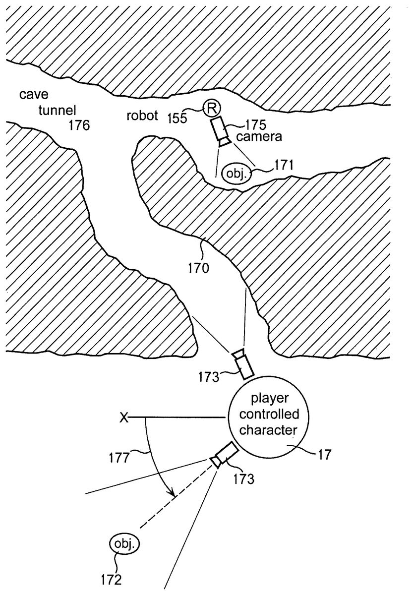
FIG. 22is a three dimensional (3D) graph illustrating Cartesian coordinates (X1Y1Z1) of an exemplary virtual camera175and coordinates (X2Y2Z2) of an exemplary object171being photographed by the virtual camera. See example inFIG. 8. Polar coordinates would also be an appropriate equivalent. For clarity, coordinates are not shown for camera215which may be the same as camera175but at different point of view location in the simulated 3D world. The viewing angle from camera215to object172is different than the viewing angle from camera175to object172.
FIG. 23illustrates a map view of a video game in which two player-controlled characters (animated character17and robot character155) are controlled by the same human player, although in some embodiments not all functions of both characters can be controlled simultaneously. If more than one player is playing this game, each player can control multiple characters individually and in groups. In theFIG. 23example, animated player-controlled character17is standing at the entrance to a cave tunnel176shown in cross-section with walls170. From the point of view of character17, object172is displayed on LCD22(FIG. 5) when her “camera”173is pointed at angle177.
FIG. 23aillustrates a player character entering cave tunnel176as shown inFIG. 23.
FIG. 24is a simplified block diagram illustrating downloading of game programs from video game system42to portable game system44. When disk reader83reads game programs into RAM90, the programs in this example are of two kinds, console program(s)151with associated data, and controller program(s)152with associated data. Controller program152is transmitted to RAM53in portable game system44and executed in microprocessor50. Console program151is stored in RAM90and executed by microprocessor86which generates animated picture data146representing one or more animated characters with plural body parts performing an action. This picture data stored in RAM146is converted to a video signal by video generator117(seeFIG. 18) that is passed to TV11by way of cable41(FIG. 18) and is displayed as animated pictures on TV screen56. Microprocessor86also generates data records which it sends (arrow154) to portable game system44. Various record formats may be used by programs151and152.
FIG. 25illustrates data flow between two video game systems42, messaging server120, and portable game system44. When the operators of the two systems42logon to messaging server120, they are registered as clients on the messaging server. System42on the left loads a multiple-player game from disk43into RAM90. Meanwhile System42on the right loads the same multiple-player game from disk43into RAM90on the right. Processors86in both systems42execute the game programs which generate data representing a simulated 3D game world in RAM90in both systems.
As the game progresses, system42on the left generates changes to the original game world that reflect movements of objects and other changes to variables in the simulated game world. These changes are cumulative and inFIG. 25are illustrated separately from the original game world. As described above with reference toFIG. 13, every time there is a change to a variable in the simulated game world, record is generated detailing the change. This record is transmitted through Internet121to system42on the right ofFIG. 25, either directly or through messaging server120. When system42on the right receives the change record, it is processed and incorporated into the cumulative changes to the simulated game world in RAM90on the right so that both simulated game worlds including cumulative changes are substantially the same.
System42on the right generates first picture data for display of the motorcyclist character18moving in the simulated game world on TV11that agree with any changes to the game world that affect character18or other objects that he may be seen with.
System42on the right also generates and transmits game data to portable game system44through data link45. This game data represents all of the changes that have occurred to the simulated game world that affect the area of the game world that will be displayed on LCD22on portable game system44. In this example the operator of portable system44wants to display on LCD22the other player's character in the dinosaur scene that is also being displayed on TV screen56.
The term “video” may include composite, non-composite, RGB, component, monochrome, color, analog, digital, raster scanned, and the like.
The term “portable game system” is a term of art that means a handheld game system that contains a discrete display device (e.g. LCD) and can be operated as an independent game system without any connection to other systems or displays.
The details of video game system42and portable game system44are given here only as examples and numerous other designs may be used.
The term “LCD” (liquid crystal display) has been used herein as an illustrative example of any display apparatus having discrete dot-matrix picture elements.
The term “program” as used herein may consist of more than one loadable module and typically includes executable instruction data and any other data that is typically part of a program module or modules.
Although I have described my invention with a degree of particularity in connection with what is presently considered to be the most practical and preferred embodiments, the forgoing description has been made only by way of illustration and example and is not to be interpreted as restrictive or limiting as to the meaning of words in the patent or its claims. It is understood that various modifications, variations, arrangements, and/or equivalents, can be devised without departing from the spirit and scope of the invention which is defined by the claims.
REFERENCE NUMBERS IN DRAWINGS
10human game player11television (TV) set or video monitor12human game player14control switch15direction control switch16external memory17player character18player character19linked system in general20joystick22LCD screen33LCD pictures34LCD pictures40serial data port in portable system41video signal cable to TV42video game system console43optical disk44portable game system45data link from console to portable game system47portable game system49cursor50cpu processor in portable system53RAM in portable system56video screen57control switch60program process62program process63program process64program process65program decision66program decision67program decision68program process69program process70program process71program process72program decision73program decision76boot ROM in portable system78data record82tracks molded into disk83optical disk reader84security processor86cpu processor in console system87serial data connector88serial port (UART)90RAM in console system91boot ROM in console system92address bus in portable system93data bus in portable system117video signal generator119LCD driver120messaging server121network125serial port (UART)137network interface138network interface146animated picture data151program for console system152program for portable system153data flow from portable to console154data flow from console to portable157program decision158program process171generic object172generic object173virtual camera175virtual camera185conventional handheld control unit186data link to auxiliary display187table or other physical support192conventional handheld control unit215virtual camera228generic object229player controlled object230cartridge socket249wireless data link250transceiver251transceiver300direct memory access (DMA)301image coprocessor302video RAM316image coprocessor317data bus in console318address bus in console319serial port (UART)322cartridge with button switches
Claims
- A method for use in a multi-player game system having a first game apparatus operated by a first player and a second separately housed game apparatus operated by a second player, the method comprising the steps of: (a) generating in said first and second game apparatus polygon vertex data that represent shapes of a 3-dimensional first player-controlled object controlled by said first player and moving in a simulated 3-dimensional game world that contains a simulated passageway between first and second portions of said game world;(b) rendering said polygon data to generate pixels that represent said first player-controlled object from variable viewpoints for display on a display device;(c) generating digital location data in said first game apparatus that specify variable locations of said first player-controlled object in said game world;(d) initiating transmission of said location data from said first game apparatus through a first data transmission link to said second game apparatus;(e) initiating transmission of data from said first game apparatus through said data transmission link to said second game apparatus to cause said second game apparatus to send first status data through said data transmission link to notify said first game apparatus of availability of said simulated passageway for use by said first player-controlled object;(f) receiving said first status data from said second game apparatus through said data transmission link that indicates to said first game apparatus that said simulated passageway is unavailable for use by said first player-controlled object;(g) storing said first status data in said first game apparatus as attribute data having a value of unavailable for said simulated passageway;(h) receiving second status data from said second game apparatus through said data transmission link that indicates to said first game apparatus that said simulated passageway is available for use by said first player-controlled object;(i) changing said value of said attribute data from unavailable to available for said simulated passageway in accordance with said second status data;(j) generating picture data for display on said display device that represents said first player-controlled object making use of said simulated passageway after said first game apparatus has determined from said attribute data that said simulated passageway is available for use by said first player-controlled object;and (k) initiating transmission of notification data from said first game apparatus through said data transmission link to notify said second game apparatus that said first player-controlled object has completed use of said simulated passageway.
- The method of claim 1 , wherein said simulated passageway is any from the group comprising: door, doorway, entrance, entranceway, entryway, gate, gateway, hatch, tunnel, ingress, egress, opening, inlet, accessway, passage, portal, exit, cave, other passageway, and a combination thereof.
- The method of claim 1 , wherein said data transmission link comprises any transmission means from the group comprising: wireless transmission, transmission through the Internet, transmission through a telephone network, transmission through an Internet server.
- The method of claim 1 , wherein said data transmission link comprises transmission through an Internet server that also provides instant messaging for communication of messages between registered players.
- The method of claim 1 , wherein said display device is an LCD device.
- The method of claim 1 , further comprising the step of generating control data in a touchscreen on a portable game system to control movements of said player-controlled object.
- The method of claim 1 , further comprising the step of generating control data in a touchscreen on a portable game system to control access to said passageway.
- The method of claim 1 , further comprising the step of transmitting game data from said first game apparatus to a portable game system to display a portion of said 3-dimensional world from a 3-dimensional viewpoint in said simulated game world.
- The method of claim 1 , further comprising the step of downloading at least one program from one of said game apparatus for execution in a portable game system.
- A method for use in a multi-player game system having a first game apparatus operated by a first player and a second separately housed game apparatus operated by a second player, the method comprising the steps of: (a) generating in said first and second game apparatus polygon vertex data that represent shapes of a 3-dimensional first player-controlled object controlled by said first player and moving in a simulated 3-dimensional game world that contains a simulated passageway between first and second portions of said game world;(b) rendering said polygon data to generate pixels that represent said first player-controlled object from variable viewpoints for display on a display device;(c) receiving first status data from said second game apparatus through said data transmission link to said first game apparatus that indicates that said simulated passageway is unavailable for use by said first player-controlled object;(d) storing said first status data in said first game apparatus as attribute data having a value of unavailable for said simulated passageway;(e) initiating transmission of notification data from said first game apparatus through a data transmission link to said second game apparatus to notify said second game apparatus that said simulated passageway is required for use by said first player-controlled object;(f) receiving second status data through said data transmission link from said second game apparatus that indicates to said first game apparatus that said simulated passageway is available for use by said first player-controlled object;(g) changing said value of said attribute data from unavailable to available for said simulated passageway in accordance with said second status data;(h) generating picture data for display on said display device that represents said first player-controlled object making use of said simulated passageway after said first game apparatus has determined from said attribute data that said simulated passageway is available for use by said first player-controlled object;and (i) initiating transmission of notification data from said first game apparatus through said data transmission link to notify said second game apparatus that said first player-controlled object has completed use of said simulated passageway.
- A computer readable data storage medium for use with a first game apparatus that communicates through a data transmission link with at least a second game apparatus, said first game apparatus having a first processor that generates picture data that represents a simulated passageway between portions of a simulated 3-dimensional game world populated with at least one player-controlled simulated object for display on a first display device, the data storage medium storing game program instructions comprising;(a) executable instructions that cause said first processor to initiate transmission of data through said data transmission link to said second game apparatus to cause said second game apparatus to send first status data through said data transmission link to said first game apparatus regarding availability of said simulated passageway for passage of said player-controlled simulated object;(b) executable instructions that cause said first processor to receive said first status data through said data transmission link from said second game apparatus that indicates that said simulated passageway is unavailable for passage of said player-controlled simulated object;(c) executable instructions that cause said first processor to store said first status data in said first game apparatus as attribute data having a value of unavailable for said simulated passageway;(d) executable instructions that cause said first processor to receive second status data through said data transmission link from said second game apparatus that indicates that said simulated passageway is available for passage of said player-controlled simulated object after receipt of said first status data by said first processor;(e) executable instructions that cause said first processor to change said value of said attribute data from unavailable to available for said simulated passageway in accordance with said second status data;(f) executable instructions that cause said first processor to generate picture data representing said player-controlled object making use of said simulated passageway after said first processor has determined from said attribute data that said simulated passageway is available for use by said first player-controlled object;and (g) executable instructions that cause said first processor to initiate transmission of third status data through said data transmission link to notify said second game apparatus that said player-controlled simulated object has completed passage of said simulated passageway.
- The data storage medium of claim 11 , wherein said data storage medium is from the group comprising: an optically coded medium, a semiconductor memory, and a magnetic data storage medium.
- The data storage medium of claim 11 , wherein said data storage medium is a writable data memory into which said game program instructions are downloaded from a separately housed system.
- The data storage medium of claim 11 , wherein said first game apparatus is from the group comprising: video game system, handheld game system, computer, and a combination thereof.
- The data storage medium of claim 11 , wherein said data transmission link comprises one from the group of: a computer, the Internet, a network server, wire transmission, wireless transmission, video game system, and a combination thereof.
Disclaimer: Data collected from the USPTO and may be malformed, incomplete, and/or otherwise inaccurate.