U.S. Pat. No. 7,256,779
VIDEO GAME PLAY USING PANORAMICALLY-COMPOSITED DEPTH-MAPPED CUBE MAPPING
AssigneeNintendo Co., Ltd.
Issue DateAugust 8, 2003
Illustrative Figure
Abstract
Video game play rendered using a panoramic view of a cube map style rendering uses an associated depth map to supply three-dimensionality to the pre-rendered scene. The resulting panoramic rendering may be indistinguishable from rendering the original scene in real-time except that the background is of pre-rendered quality.
Description
DETAILED DESCRIPTION FIG. 1shows an example interactive 3D computer graphics system50. System50can be used to play interactive 3D video games with interesting stereo sound. It can also be used for a variety of other applications. In this example, system50is capable of processing, interactively in real-time, a digital representation or model of a three-dimensional world. System50can display some or all of the world from any arbitrary viewpoint. For example, system50can interactively change the viewpoint in response to real-time inputs from handheld controllers52a,52bor other input devices. This allows the game player to see the world through the eyes of someone within or outside of the world. System50can be used for applications that do not require real-time 3D interactive display (e.g., 2D display generation and/or non-interactive display), but the capability of displaying quality 3D images very quickly can be used to create very realistic and exciting game play or other graphical interactions. To play a video game or other application using system50, the user first connects a main unit54to his or her color television set56or other display device by connecting a cable58between the two. Main unit54in this example produces both video signals and audio signals for controlling color television set56. The video signals are what controls the images displayed on the television screen59, and the audio signals are played back as sound through television stereo loudspeakers61L,61R. The user also connects main unit54to a power source. This power source may be a conventional AC adapter (not shown) that plugs into a standard home electrical wall socket and converts the house current into a lower DC voltage signal suitable for powering the main unit54. Batteries could be used in other implementations. The user may use hand controllers52a,52bto control main unit54. Controls60can be used, for example, to specify the direction (up or down, left or right, ...
DETAILED DESCRIPTION
FIG. 1shows an example interactive 3D computer graphics system50. System50can be used to play interactive 3D video games with interesting stereo sound. It can also be used for a variety of other applications.
In this example, system50is capable of processing, interactively in real-time, a digital representation or model of a three-dimensional world. System50can display some or all of the world from any arbitrary viewpoint. For example, system50can interactively change the viewpoint in response to real-time inputs from handheld controllers52a,52bor other input devices. This allows the game player to see the world through the eyes of someone within or outside of the world. System50can be used for applications that do not require real-time 3D interactive display (e.g., 2D display generation and/or non-interactive display), but the capability of displaying quality 3D images very quickly can be used to create very realistic and exciting game play or other graphical interactions.
To play a video game or other application using system50, the user first connects a main unit54to his or her color television set56or other display device by connecting a cable58between the two. Main unit54in this example produces both video signals and audio signals for controlling color television set56. The video signals are what controls the images displayed on the television screen59, and the audio signals are played back as sound through television stereo loudspeakers61L,61R.
The user also connects main unit54to a power source. This power source may be a conventional AC adapter (not shown) that plugs into a standard home electrical wall socket and converts the house current into a lower DC voltage signal suitable for powering the main unit54. Batteries could be used in other implementations.
The user may use hand controllers52a,52bto control main unit54. Controls60can be used, for example, to specify the direction (up or down, left or right, closer or further away) that a character displayed on television56should move within a 3D world. Controls60also provide input for other applications (e.g., menu selection, pointer/cursor control, etc.). Controllers52can take a variety of forms. In this example, controllers52shown each include controls60such as joysticks, push buttons and/or directional switches. Controllers52may be connected to main unit54by cables or wirelessly via electromagnetic (e.g., radio or infrared) waves.
To play an application such as a game, the user selects an appropriate storage medium62storing the video game or other application he or she wants to play, and inserts that storage medium into a slot64in main unit54. Storage medium62may, for example, be a specially encoded and/or encrypted optical and/or magnetic disk. The user may operate a power switch66to turn on main unit54and cause the main unit to begin running the video game or other application based on the software stored in the storage medium62. The user may operate controllers52to provide inputs to main unit54. For example, operating a control60may cause the game or other application to start. Moving other controls60can cause animated characters to move in different directions or change the user's point of view in a 3D world. Depending upon the particular software stored within the storage medium62, the various controls60on the controller52can perform different functions at different times.
Example Non-Limiting Electronics and Architecture of Overall System
FIG. 2shows a block diagram of example components of system50. The primary components include:
a main processor (CPU)110,
a main memory112, and
a graphics and audio processor114.
In this example, main processor110(e.g., an enhanced IBM Power PC 750 or other microprocessor) receives inputs from handheld controllers108(and/or other input devices) via graphics and audio processor114. Main processor110interactively responds to user inputs, and executes a video game or other program supplied, for example, by external storage media62via a mass storage access device106such as an optical disk drive. As one example, in the context of video game play, main processor110can perform collision detection and animation processing in addition to a variety of interactive and control functions.
In this example, main processor110generates 3D graphics and audio commands and sends them to graphics and audio processor114. The graphics and audio processor114processes these commands to generate interesting visual images on display59and interesting stereo sound on stereo loudspeakers61R,61L or other suitable sound-generating devices.
Example system50includes a video encoder120that receives image signals from graphics and audio processor114and converts the image signals into analog and/or digital video signals suitable for display on a standard display device such as a computer monitor or home color television set56. System50also includes an audio codec (compressor/decompressor)122that compresses and decompresses digitized audio signals and may also convert between digital and analog audio signaling formats as needed. Audio codec122can receive audio inputs via a buffer124and provide them to graphics and audio processor114for processing (e.g., mixing with other audio signals the processor generates and/or receives via a streaming audio output of mass storage access device106). Graphics and audio processor114in this example can store audio related information in an audio memory126that is available for audio tasks. Graphics and audio processor114provides the resulting audio output signals to audio codec122for decompression and conversion to analog signals (e.g., via buffer amplifiers128L,128R) so they can be reproduced by loudspeakers61L,61R.
Graphics and audio processor114has the ability to communicate with various additional devices that may be present within system50. For example, a parallel digital bus130may be used to communicate with mass storage access device106and/or other components. A serial peripheral bus132may communicate with a variety of peripheral or other devices including, for example:a programmable read-only memory and/or real-time clock134,a modem136or other networking interface (which may in turn connect system50to a telecommunications network138such as the Internet or other digital network from/to which program instructions and/or data can be downloaded or uploaded), andflash memory140.
A further external serial bus142may be used to communicate with additional expansion memory144(e.g., a memory card) or other devices. Connectors may be used to connect various devices to busses130,132,142.
Exemplary Non-Limiting Video Game Panoramic Compositing Technique
FIG. 3Ashows an example flowchart of illustrative non-limiting video game play on the system shown inFIGS. 1 and 2. The software used to control and define the operations shown inFIG. 3Amay be stored in whole or in part on mass storage device62which is loaded into or otherwise coupled to video game system50before game play begins. In another example, the software may be downloaded over network138and loaded into internal memory of the video game system50for execution.
To play an exemplary illustrative video game, the user may depress a “start” or other control which causes the execution of program instructions to initialize game play (FIG. 3A, block302). Once the game has begun executing, the system50may acquire user inputs from handheld controllers52or other input sources (FIG. 3A, block304) and define corresponding viewing angle and frustum parameters corresponding to one or more virtual camera or other views (FIG. 3A, block306). The software may also define one or more moving objects such as moving characters and associated animation parameters (FIG.3A, block308). The game may then render a frame onto display56(FIG. 3A, block310). Assuming the game is not over (“no” exit to decision block312), blocks304-310are repeated rapidly (e.g., thirty or sixty times each second) to provide interactive video game play.
FIG. 3Bshows an example “render” routine used by theFIG. 3Avideo game software to provide panoramic compositing allowing rich, complex 3D virtual scenes and worlds. In the exemplary illustrative embodiment, the first two blocks320,322ofFIG. 3Bare performed in advance (“pre-rendered”) before real-time rendering, and the remaining blocks324-332are performed during real-time rendering. The pre-rendering blocks320,322in one exemplary illustrative embodiment are not performed by video game system50at all, but rather are performed well in advance by another computer or graphics workstation that may for example use complicated, time-consuming non-real-time 3D rendering techniques such as ray tracing. In other exemplary embodiments, blocks320,322can be performed as part of the “initialized game play” block302shown inFIG. 3A. In still other embodiments, if real-time processing resources are available, blocks320,322can be performed by system50at the beginning of a game play sequence or the like.
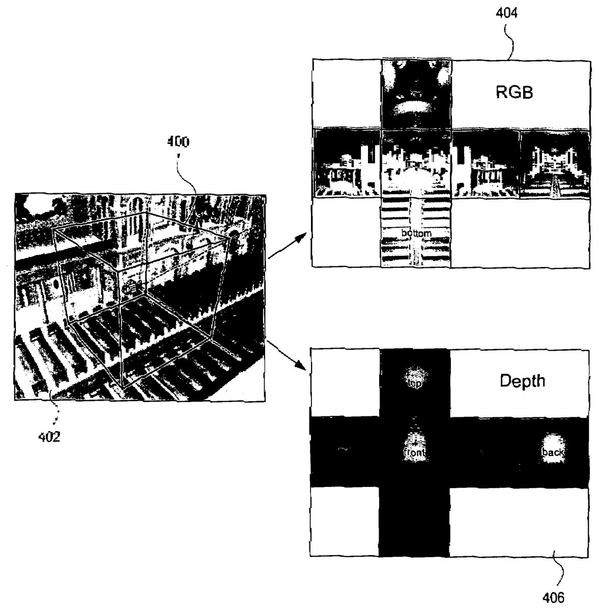
To perform the pre-render exemplary process, a virtual cube400is defined within a virtual three-dimensional universe. As shown in illustrativeFIG. 4A, virtual cube400may be defined within any realistic or fantastic scene such as, for example, the interior of a medieval cathedral. The cube400is used for cube mapping. A panoramic view is created using a cube map style rendering of the scene from a chosen location as shown inFIG. 4Ato provide more camera freedom for pre-rendered games. This technique in one exemplary illustration keeps the viewpoint static but allows the player to look around in any direction.
In more detail, an exemplary 3D scene402is created using any conventional 3D modeling application. The scene is rendered out in six different images as if looking through the six different faces of cube400with the viewpoint at the center of the cube (FIG. 3B, block320). This produces a high-quality off-line rendered RGB or other color cube map404representation of the scene as shown inFIG. 4B. In exemplary illustrative embodiment, a depth map406of the same scene is also created based on the same six cube image faces (seeFIG. 4Cand block322ofFIG. 3B).
During real-time video game play (FIG. 3B, block324), video game system50loads the pre-rendered cube map face into its embedded frame buffer memory and loads the pre-rendered depth map corresponding to that face into a memory such as a Z (depth) buffer (FIG. 3B, blocks324,326). In one exemplary embodiment, the cube map404and depth map406such as shown inFIGS. 4B,4C may be stored on mass storage device62or it may be downloaded over network138.
Once these data structures are in appropriate memory of video game system50, the video game software renders one or more real-time objects such as animated characters into the frame buffer using the same view point and frustum parameters in one exemplary embodiment to provide a composite image (FIG. 3B, block328). Such rendering may make use of the depth information406(e.g., through use of a conventional hardware or software-based Z-compare operation and/or collision detection) to provide hidden surface removal and other effects.
This same process is repeated in the exemplary embodiment for each of the other cube-mapped faces to produce a post-composited cube map (FIG. 3B, block330). As will be appreciated by those of ordinary skill in the art, in at least some applications it is possible to reduce the number of cube mapped faces to composite by performing a rough “bounding box” or other type test determining which cube mapped faces (e.g., one, two, three or a maximum) the moving object image is to be displayed within, thereby avoiding the need to composite these unaffected faces. There are cases where a character could span more than three faces of the cube. (And if the final frustum is wide enough we could see more than three faces at once also.) It is the intersection between three things which is rendered in real-time and composited with the cube map in the exemplary embodiment:the final frustum;the moving/animating character (which may be approximated using bounding boxes, convex hull, or other method);the cube map faces, or predefined portions thereof (in one example implementation we split each cube face into four pieces, thus reducing the amount of area that needed to be composited).
Once a complete post-composited cube map has been created, it is then applied to a cube or other mesh and rendered with the current projection matrix to create a panoramic image with desired viewing angle and frustum parameters (FIG. 3B, block332). SeeFIGS. 6A and 6B. In one exemplary illustrative non-limiting embodiment, this final rendering step simply applies the multiple cube map faces on the inside of a cube mesh and proceeds by panoramically rendering in a conventional fashion with a normal projection matrix using conventional hardware and/or software rendering techniques and engines. The result should be indistinguishable from rendering the original scene in real-time in the first place except that the background is at pre-rendered quality.
Panoramic Compositing—Example Implementation Details
Example Art Path for Panoramic Compositing:
1. Pre-render the RGB and Depth buffers404,406for each cube face from a CG tool such as Maya or other standard tool.
2. Possible to use a resolution of for example 1024×1024 for each field of view (“FOV”) 90 degree cube face. If we consider the case where the viewing direction is towards the center of a face, we get a 1:1 texel to pixel ratio with an NTSC 640×480 screen with a horizontal FOV of 38.7°, and vertical FOV of 28°. When we face the edges or corners of the cube, the texel to pixel ratio increases (maximum 1.73 times more at the corners).
3. In an example embodiment, due to frame-buffer size limitations, or for efficiency reasons it may be useful to perform the compositing in pieces less than the full size of a cube face, and copy these intermediate results to texture maps for final rendering in a separate pass. For example, each face of the original cube could be split into four pieces of 512×512 each. Other techniques could be used in other embodiments.
4. Regarding the format of the Z-textures: One example implementation uses 16-bit Z textures. The value which must be stored in the Z texture is not actually Z, but can be:
far(Z-near)Z(far-near)
5. Another detail is worth mentioning regarding pre-rendered Z (depth) buffers406. With pre-rendered RGB buffers404, we have the luxury of doing a fully super-sampled rendering to give smooth edges, and correct filtering. However, with Z we may have less resolution (e.g., only one sample per pixel in some cases). When we try to composite our real-time graphics with the pre-rendered graphics, this can cause artifacts. The worst of these artifacts is when the Z value says a pixel is foreground, but the RGB average is closer to the background color. Then when a character is between the foreground and the background, we may get a halo of background color around foreground objects. In order to minimize this effect, we have found it is better to bias towards using the background Z value as the representative Z value for pixels whose RGB is a mixture of foreground and background colors. To achieve this kind of control over the source textures, one can render at a higher resolution initially and pre-process the data down to the final size.
This technique may be useful for another reason as well. For example, some conventional offline renderers may use jittered sampling, and thus the outlines of straight edged objects can sometimes become ragged unless rendered at a higher resolution initially and further processed to get a cleaner Z image. Other example embodiments may not be concerned with this issue.
6. Optimization. There is no need to composite all panels or cube face images in the pre-pass. Only those which overlap both the final frustum and the real-time characters need to be composited and copied out.
Example Images
FIGS. 7A-7Gshow example images that are possible in the cathedral interior scene ofFIG. 4Awhen an exemplary moving object500interacts with the cube-mapped scene. The moving object500shown inFIGS. 7A-7Gis a cube for purposes of illustration only—any animated or non-animated object of any configuration could be used instead.FIG. 7Ashows moving object500obstructing and being obstructed by different portions of the cube-mapped virtual 3D environment—in this case a railing502on the clere story of the virtual cathedral.FIG. 7Bshows the same moving object500obstructing and being obstructed by a column504and also descending and thus being obstructed by portions of the tile floor surface506of the virtual cathedral.FIG. 7Cshows the same cubic moving object500obstructing and being obstructed by ceiling details such as shown inFIG. 5D.FIG. 7Dshows the moving object500obstructing and being obstructed by an archway detail508.FIG. 7Eshows moving object500obstructing and being obstructed by different portions of a pew510.FIG. 7Fshows moving object500obstructing and being obstructed by different portions of a column512adjacent the cathedral nave.FIG. 7Gshows a magnified detail of theFIG. 7Fimage.
In the exemplary illustrative embodiment, images such as those shown inFIGS. 7A-7Gcan be created by giving the video game user control over moving object500so it can be moved anywhere within the three-dimensional scene defined by the depth-mapped panoramic cube map environment. While the exemplary moving object500shown inFIGS. 7A and 7Ghas the characteristic of being able to pass through virtual solid structure in order to better illustrate hidden surface removal, it is also possible to provide other characteristics such as for example collision detection so the moving object can bounce off or otherwise interact with the depth of the panoramically-rendered scene.
Example Enhancements to Panoramic Compositing
Example Enhanced Antialiasing:
The quality of composited renderings could be improved with better antialiasing. This can be achieved by allowing multiple Z values and multiple color values for edge pixels of foreground objects.
We would get a lot of benefit even with just two Z values per pixel. This allows a high quality solution to the halo artifacts which occur when real-time CG characters are positioned between background and foreground pre-rendered elements in 1-depth-sample per pixel compositing.
The following algorithm can be used to render anti-aliased edges in the two depth samples per pixel case.
1. Render the furthest depth value and RGB value first.
2. Composite the real-time character as usual.
3. Alpha-blend on the foreground edges—alpha comes from foreground coverage value.
Note that foreground edges occupy only a small percentage of the pixels, so the antialiasing pass does not need to consume a full frame's worth of fill-rate bandwidth.
Example Panoramic Movie Compositing
It may also be desirable to use movie textures to further enhance the realism, and promote the illusion that the full scene is being rendered in real-time. In many cases, it would be desirable to be able to specify particular regions of the scene to be animated, to help minimize the storage, bandwidth and decompression costs.
If the animations are restricted to lighting only, RGB animation is sufficient. If we want animated foreground objects then animated Z-textures can be used.
While the technology herein has been described in connection with exemplary illustrative non-limiting embodiments, the invention is not to be limited by the disclosure. For example, the pre-rendered environment could be a shape other than a cube. In some cases it would not be necessary to cover the whole panorama. For example if the game did not require the camera to point at the floor or ceiling, a tessellated cylinder could be an efficient shape to use for the pre-rendered environment. Example embodiments can work, for example, with environments composed of multiple planar projected images to achieve a wide degree of camera directional freedom using single planar images. As another example, the technique does not rely on the source material being pre-rendered; the environment could conceivably originate from real world photographs, and associated depth-captured images for example. The invention is intended to be defined by the claims and to cover all corresponding and equivalent arrangements whether or not specifically disclosed herein.
Claims
- A video game playing method comprising: loading a pre-determined environment-cube-mapped image having multiple planar projected images and associated depth maps;receiving real-time interactive inputs from a user;at least in part in response to said real-time interactive user inputs, compositing at least one additional three-dimensional object, having plural non-coplanar surfaces, into a scene comprising said environment-cube-mapped images;in response to said received user input, moving said three-dimensional object having said plural non-coplanar surfaces within said environment-cube-mapped images, said compositing using said depth maps to selectively render at least portions of said three-dimensional object to provide a composite image;said compositing performing depth comparisons between depth values associated with said plural non-coplanar surfaces of said three-dimensional object and said depth maps associated with said environment-cube-mapped multiple planar projected images so as to selectively allow said three-dimensional object surfaces to be partially occluded by portions of said environment-cube-mapped images as said user inputs cause said three-dimensional object to move and to thereby interact with said environment-cube-mapped images;and using a three-dimensional graphics engine to panoramically render said composite image using a desired viewing angle to provide interactive 3D video game play.
- The method of claim 1 wherein said environment-cube-mapped image is pre-rendered.
- The method of claim 1 including performing said compositing with a home video game system, and further including displaying rendering results on a home color television set.
- The method of claim 1 wherein said receiving comprises receiving interactive real-time user inputs via at least one handheld controller, and said method further includes defining animation of said three-dimensional object at least in part in response to said inputs.
- The method of claim 1 wherein said rendering comprises applying said composite image to a mesh, and rendering said mesh using a projection matrix to apply desired viewing angle and frustum parameters.
- The method of claim 1 further including testing whether said three-dimensional object intersects any of multiple faces of said environment-cube-mapped image in at least two dimensions.
- The method of claim 1 further including performing Z comparison and removing hidden surfaces in response to said Z comparison.
- The method of claim 1 further including performing said rendering using a frame buffer.
- The method of claim 1 further including detecting collisions between the three-dimensional object surfaces and the environment cube mapped images.
- A computer readable storage medium storing instructions that, when executed by a home video game system or personal computer, provide interactive real-time video game play on a display at least in part in response to user input, said storage medium storing: at least one pre-rendered cubic environment map;at least one pre-rendered depth map corresponding to said cubic environment map;instructions that, when executed, composite at least portions of said pre-rendered cubic environment map with at least one dynamically-generated three-dimensional object having plural non-coplanar surfaces, said compositing based at least in part on said pre-rendered depth map;instructions that, in response to received user inputs, interactively move said three-dimensional object within said cubic environment map;said compositing performing depth comparisons between said plural non-coplanar surfaces of said three-dimensional object and said cubic environment map so as to selectively allow said three-dimensional object surfaces to be partially occluded by portions of said cubic environment map as said user input causes said three-dimensional object to move within and interact with said cubic environment map;and instructions that control a three-dimensional graphics engine to generate a rendered panoramic image based at least in part on said depth comparisons.
- The storage medium of claim 10 wherein said pre-rendered cubic environment map comprises six images as if looking through faces of a cube with the viewpoint at the center of the cube.
- The storage medium of claim 10 wherein said compositing includes rendering a real-time object into a frame buffer storing said pre-rendered cubic environment map using dynamically defined view port and/or frustum parameters.
- The storage medium of claim 10 further storing instructions that detect a collision between the three-dimensional object and the cubic environment map.
- A video game playing system comprising: means for loading a pre-determined environment-cube-mapped image having multiple planar projected images and associated multiple depth maps;means for, at least in part in response to real-time interactive user input, compositing into said mapped images at least one additional three dimensional object having plural non-coplanar surfaces;said compositing means using said depth maps to selectively render at least portions of said three-dimensional object within the cube mapped image to provide a composited mapped image;means for receiving interactive inputs from a user;means for moving said three-dimensional object within said mapped image at least in part in response to said received user inputs, said compositing means dynamically performing depth comparisons between said plural non-coplanar surfaces of said three-dimensional object and said mapped image so as to selectively allow said three-dimensional object surfaces to be partially hidden by portions of said mapped image as said user input moves said three-dimensional object within said mapped image;and means for using a three-dimensional graphics engine to panoramically render said composited mapped image using a desired viewing angle to provide interactive 3D video game play.
- The system of claim 14 wherein said pre-determined environment cube mapped image is created at authoring time.
- The system of claim 14 wherein said pre-determined environment cube mapped image is created before game play.
- The system of claim 14 wherein said compositing means includes means for compositing said composited mapped image in pieces less than the full size of a cube face.
- The system of claim 14 wherein said compositing means includes means for representing said depth maps using Z textures.
- The system of claim 14 wherein said compositing means composites and outputs only those cube face images which overlap both the final frustum and real-time objects to be imaged.
- The system of claim 14 further including means for using at least one movie texture to provide said environment cube mapped image, and means for specifying portions of said environment map to be animated.
- The system of claim 14 further including means for detecting a collision between the three-dimensional object surfaces and the cube mapped image.
- A video game playing system comprising: means for loading a pre-determined environment-mapped image having multiple planar projected images and associated multiple depth map images;means for at least in part in response to real-time interactive user input, compositing at least one additional object into said mapped images, said compositing using said depth map to selectively render at least portions of said object into the cube mapped image to provide a composited mapped image;and means for panoramically rendering said composited mapped image using a desired viewing angle and frustum to provide interactive video game play, wherein said multiple depth map images are biased towards using background Z value as the representative Z value for pixels whose RGB is a mixture of foreground and background colors.
Disclaimer: Data collected from the USPTO and may be malformed, incomplete, and/or otherwise inaccurate.