U.S. Pat. No. 7,235,748
VIDEO GAME CONTROLLER AND GAME APPARATUS
AssigneeSSD Company Limited
Issue DateApril 13, 2005
Illustrative Figure
Abstract
The game apparatus is provided with the cylindrical portion rotating with the axis on the side face of the base portion of the master control lever. Two projecting parts are sticking out from the columnar surface of the cylindrical portion. In addition, two leaf switches are provided corresponding to the master control lever. The leaf switch is turned on when the projecting part contacts with the contact member of the leaf switch while the master control lever is rotating. In this way, operation of the master control lever is detected by using the leaf switches rather than rotary switches.
Description
DESCRIPTION OF THE PREFERRED EMBODIMENTS In what follows, an embodiment of the present invention will be explained in conjunction with the accompanying drawings. Meanwhile, like references indicate the same or functionally similar elements throughout the respective drawings, and therefore redundant explanation is not repeated. FIG. 1is a view showing the overall configuration of a game system in accordance with the embodiment of the present invention. As illustrated inFIG. 1, this game system includes a game apparatus1and a television monitor100. The game apparatus1displays images such as rails and scenery seen from a driver's seat on the television monitor100, and performs a simulation game of driving a train. In this embodiment, the game apparatus1also serves as a video game controller, however this will be explained later. The television monitor100is provided with a screen103on its front and an AV terminal105below the screen103. An AV terminal326(to be explained later) of the game apparatus1is connected to the AV terminal105of the television monitor100by an AV cable110. A direct current power voltage is applied to the game apparatus1by an AC adaptor120. Alternatively, instead of using the AC adapter120, the game apparatus1can be supplied with the direct current power voltage from a battery (not shown). FIG. 2is a perspective view of the game apparatus1ofFIG. 1. As illustrated inFIG. 2, the game apparatus1is provided with a T-shaped master control lever3on the left-hand of an upper surface of a housing2of the game apparatus1in a manner that the master control lever3can rotate within a vertical plane. A brake lever5is attached on the right-hand of the upper surface of the housing2of the game apparatus1in a manner that the brake lever5can rotate within a horizontal plane. In addition, the game apparatus1is provided, around the center of the upper surface of the housing2, with a light switch7, a wiper switch9, a door switch11, an ...
DESCRIPTION OF THE PREFERRED EMBODIMENTS
In what follows, an embodiment of the present invention will be explained in conjunction with the accompanying drawings. Meanwhile, like references indicate the same or functionally similar elements throughout the respective drawings, and therefore redundant explanation is not repeated.
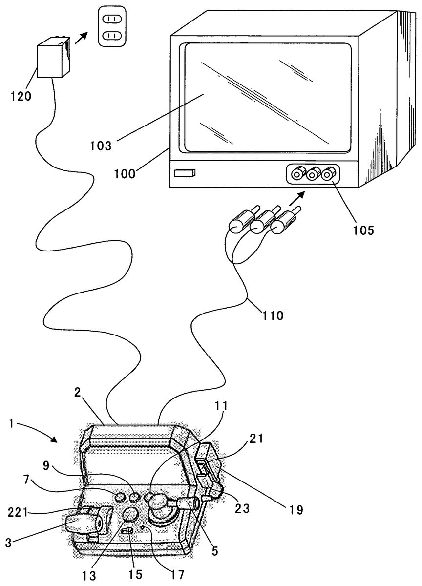
FIG. 1is a view showing the overall configuration of a game system in accordance with the embodiment of the present invention. As illustrated inFIG. 1, this game system includes a game apparatus1and a television monitor100. The game apparatus1displays images such as rails and scenery seen from a driver's seat on the television monitor100, and performs a simulation game of driving a train. In this embodiment, the game apparatus1also serves as a video game controller, however this will be explained later.
The television monitor100is provided with a screen103on its front and an AV terminal105below the screen103. An AV terminal326(to be explained later) of the game apparatus1is connected to the AV terminal105of the television monitor100by an AV cable110. A direct current power voltage is applied to the game apparatus1by an AC adaptor120. Alternatively, instead of using the AC adapter120, the game apparatus1can be supplied with the direct current power voltage from a battery (not shown).
FIG. 2is a perspective view of the game apparatus1ofFIG. 1. As illustrated inFIG. 2, the game apparatus1is provided with a T-shaped master control lever3on the left-hand of an upper surface of a housing2of the game apparatus1in a manner that the master control lever3can rotate within a vertical plane. A brake lever5is attached on the right-hand of the upper surface of the housing2of the game apparatus1in a manner that the brake lever5can rotate within a horizontal plane.
In addition, the game apparatus1is provided, around the center of the upper surface of the housing2, with a light switch7, a wiper switch9, a door switch11, an alarm whistle switch13, a power switch15and a reset switch17for resetting a system. Furthermore, a microphone holder23is attached on the right side surface of the housing2, and a microphone19is held by the microphone holder23. The microphone19is provided with a microphone switch21.
FIG. 3is a view showing a departure screen displayed on the screen103ofFIG. 1. As illustrated inFIG. 3, the departure screen is displayed by the game apparatus1on the screen103when the power switch15is turned on. The departure screen includes a train image50, a speed displaying portion52and a microphone image54. A speed of the train is displayed in the speed displaying portion52. The microphone image54is an image for instructing a player to press the microphone switch21and input voice. The train image50starts moving when the player presses the microphone switch21, inputs voice through the microphone19, and also pulls the master control lever3. Namely, the train starts moving.
Before the microphone image54is displayed, a door image (not shown) is displayed at the same place as the microphone image54. The door image is an image for indicating the player to press the door switch11to close a door of the train image50. The door is closed by pressing the door switch11.
FIG. 4is a view showing a running screen displayed on the screen103ofFIG. 1. As illustrated inFIG. 4, the running screen shows scenery to be seen from a driver's seat of the running train. Therefore, the running screen includes a scenery image65and rail images66and68to be seen from the driver's seat. In addition, the running screen includes a lighting indication portion60, a microphone input indication portion62, the speed displaying portion52, a message displaying portion64, a propulsion meter56, and a braking meter58. In addition, a start point object70is displayed on the left-hand top of the running screen, and an end point object72is displayed on the right-hand top of the running screen. In between, a running point indicating object74is displayed.
Change of the color of the lighting indication portion60indicates the player to turn lights on. When the player presses the light switch7, an image in which lights are illuminating the front is displayed. Change of the color of the microphone input indication portion62indicates the player to input voice. When the player presses the microphone switch21and inputs voice through the microphone19, the input voice is output from speakers (not shown) of the television monitor100. When the player presses the alarm whistle switch13, alarm whistle sound is output from the speakers (not shown) of the television monitor100.
Various messages are given to the player by displaying them in the message displaying portion64. For example, a message such as “turn on the wipers” is displayed. If the player presses the wiper switch9, an image in which wipers are moving is displayed.
Returning toFIG. 2, the master control lever3is used for changing speed of the train. In this embodiment, there are three phases of speed. If the speed is in the first phase (the master control lever3is set to backmost), the propulsion is “0”. If the speed is in the second phase (the master control lever3is pulled one phase from backmost), the propulsion is “1”. If the speed is in the third phase (the master control lever3is pulled one phase from the second phase), the propulsion is “2”. In case where the propulsion is “0”, the propulsion does not work to the train. The propulsion “2” is stronger than the propulsion “1”. The player can control speed of the train by operating the master control lever3. If the speed of the train becomes faster, transition of the scenery image65becomes faster. On the other hand, if the speed of the train becomes slower, transition of the scenery image65becomes slower. The propulsion meter56ofFIG. 4changes on the basis of position of the master control lever3. In other words, the needle of the meter56swings over in accordance with the propulsion.
The brake lever5is used for putting brake on the train. In this embodiment, the brake is set to three phases. In the first phase (the brake lever5is set to backmost), the braking force is “0”. In the second phase (the brake lever5is rotated one phase from the position of the first phase), the braking force is “1”. In the third phase (the brake lever5is rotated one phase from the position of the second phase), the braking force is “2”. When the braking force is “0”, the braking force does not act on the train. The braking force “2” is stronger than the braking force “1”. The player can brake the train by operating the brake lever5. After the player brakes the train, the train slows down and the scenery image65in response to the speed of the train is displayed on the screen103. The braking force meter58ofFIG. 4changes according to the position of the brake lever5. In other words, the needle of the meter58swings over in accordance with the braking force.
The start point object70in the running screen indicates a departure point, and the end point object72indicates a destination point. The running location indicating object74is used for indicating a current location of the train. Incidentally, double track is displayed on the running screen. One is referred as the rail66and the other is referred as the rail68.
FIG. 5is an exploded perspective view of the master control lever3ofFIG. 5and peripheral members. As illustrated inFIG. 5, an axis208is formed in the center of both side faces of a base portion221of the master control lever3. The master control lever3is, for example, made of polycarbonate. A supporting member220is provided with an aperture224on the left side face. A collar200is inserted from inside of the supporting member220to the aperture224. A supporting member210is provided with an aperture226on the side face. A collar202is inserted from inside of the supporting member201to the aperture226. For example, the supporting members220and210are made of ABS (acrylonitrile butadiene styrene) and the collars200and202are made of polyacetal.
The one end of the axis208is inserted to a hole of the collar200attached to the aperture224in the manner that the master control lever3can rotate. The other end of the axis208is inserted to a hole of the collar202attached to the aperture226in the manner that the master control lever3can rotate. The supporting member210is secured on the bottom portion of the supporting member220. In this way, the master control lever3can rotate within a vertical plane. Incidentally, the collars200and202are attached to prevent resins (polycarbonate and ABS in this example) from being worn away caused from friction of resins. Therefore, the collars200and202are made of self-lubricating material.
A stopper222sticks out upwardly from the bottom portion of the supporting member220. A function of the stopper222will be explained later. Holders212and214and bosses216and218are formed on inner side face of the supporting member210. Leaf switches206and204are attached to the holding member210by the holders212and214and bosses216and218. This will be explained in detail.
FIG. 6is an explanatory view showing a mounting condition of the leaf switches204and206ofFIG. 6. As illustrated inFIG. 6, the leaf switches204and206are respectively held by the holders214and212. The leaf switch204is secured by screwing a screw240into the boss218in a manner that the base of the leaf switch204is nipped between them. In the same way, the leaf switch206is secured by screwing a screw242into the boss216in a manner that the base of the leaf switch206is nipped between them.
FIG. 7is a view showing a relation between a rotation angle of the master control lever3ofFIG. 2and on/off states of the leaf switches204and206. As illustrated inFIG. 7, in case where the master control lever3is set within a range r1(within a range of 15 degrees), the two leaf switches204and206are turned off. In case where the master control lever3is set within a range r2(within a range of 50 degrees), the leaf switch204is turned on. In case where the master control lever3is set within a range r4(within a range of 25 degrees), the leaf switch206is turned on. In case where the master control lever3is set within a range r3(within a range of 20 degrees), the both two leaf switches204and206are turned on.
FIG. 8is a view showing conditions of the leaf switches204and206when the master control lever3ofFIG. 2is set within the range r1ofFIG. 7. As illustrated inFIG. 8, a cylindrical portion (sometimes referred as “a rotating body”)250is formed on the center of the right side face (in case of the state ofFIG. 5) of the base portion221of the master control lever3. The axis208is formed in alignment with an axis line of the cylindrical portion250. Projecting parts252and254are formed in such a manner as sticking out from the columnar surface (sometimes referred as “reference surface”) of the cylindrical portion250in a vertical direction to the axis line. The cylindrical portion250where the projecting parts252and254are formed rotates with the axis208accompanying with the rotation of the master control lever3.
If the master control lever3is set within the range r1, both leaf switches204and206are turned off since both contact members205and207of the leaf switches204and206come in contact with the columnar surface of the cylindrical portion250. In this case, since the stopper222ofFIG. 5hits an edge portion255formed at the base portion of the master control lever3, the master control lever3can not be rotated clockwise (in case ofFIG. 8) anymore. Incidentally,FIG. 8is showing a condition where the master control lever3is set to the first phase (the propulsion “0”).
FIG. 9is a view showing a condition of the leaf switches204and206when the master control lever3ofFIG. 2is set to within the range (r2-r3) ofFIG. 7. The range (r2-r3) is the range r2with the range3removed. As illustrated inFIG. 9, when the master control lever3is set to within the range (r2-r3), contact portions of the leaf switch204contact with each other since the contact member205of the leaf switch204is pushed by the projecting part254. Therefore, the leaf switch204is turned on. On the other hand, the leaf switch206is off since the contact member207of the leaf switch206contacts with the columnar surface of the cylindrical portion250. Incidentally,FIG. 9is showing a condition where the master control lever3is set to the second phase (the propulsion “1”).
FIG. 10is a view showing a condition of the leaf switches204and206when the master control lever3ofFIG. 2is set to within the range r3ofFIG. 7. As illustrated inFIG. 10, when the master control lever3is set to within the range r3, the leaf switch204is turned on since the contact portions of the leaf switch204come in contact with each other because the contact member205of the leaf switch204is pushed by the projecting part254. At the same time, the leaf switch206is also turned on since contact portions of the leaf switch206contact with each other because the contact member207of the leaf switch206is pushed by the projecting part252. Incidentally,FIG. 10is showing a condition where the master control lever3is set to the third phase (the propulsion “2”). In case where the leaf switches204and206are both turned on, the leaf switch206is prioritized.
FIG. 11is a view showing a condition of the leaf switches204and206when the master control lever3ofFIG. 2is set to within the range (r4-r3) ofFIG. 7. The range (r4-r3) is the range r4with the range r3removed. As illustrated inFIG. 11, when the master control lever3is set to within the range (r4-r3), the leaf switch206is turned on since the contact portions of the leaf switch206contact with each other because the contact member207of the leaf switch206is pushed by the projecting part252. On the other hand, the leaf switch204is turned off since the contact member205of the leaf switch204contacts with the columnar surface of the cylindrical portion250. In this case, since the stopper222ofFIG. 5hits an edge portion253formed at the base portion of the master control lever3, the master control lever3can not be rotated counterclockwise (in case ofFIG. 11) anymore. Incidentally,FIG. 11is showing a condition where the master control lever3is set to the third phase (the propulsion “2”).
FIG. 12is an explanatory view showing the cylindrical portion250formed at the base portion221of the master control lever3ofFIG. 8toFIG. 11. As illustrated inFIG. 12, the height “H” of the projecting part254is made higher than an interval “L0” between contact portions of the leaf switch204. In the same way, the height “H” of the projecting part252is made higher than an interval “L0” between contact portions of the leaf switch206. In this way, it is possible to turn the leaf switches204and206on without fail. For example, it is possible to determine how high the height “H” should be than the interval “L0” from designer's own experiences. In this case, the height “H” should not be too high because the leaf switches204and206might not be able to recover their original state.
In addition, it is possible to adjust an area of the range r4ofFIG. 7by adjusting the width “W1” of the projecting part252and the position of the edge253. It is also possible to adjust an area of the range r2ofFIG. 7by adjusting the width “W2” of the projecting part254. Furthermore, it is possible to adjust an area of the range r3ofFIG. 7by adjusting the interval “L1” between the projecting parts252and254. Still further, it is possible to adjust an area of the range r1of FIG.7by adjusting the position of the edge255of the cylindrical portion250and the width “W2” of the projecting part254.
The master control lever3has been explained accompanying withFIG. 5 to 12. Incidentally, the brake lever5controls on/off of two leaf switches340and342(to be explained later) and enables to set three phases using same mechanism as the master control lever3
FIG. 13is a view showing an electrical structure of the game apparatus1ofFIG. 2.FIG. 14Ais a circuit diagram of a master control switch unit308ofFIG. 13.FIG. 14Bis a circuit diagram of a brake switch unit310ofFIG. 13.FIG. 14Cis a circuit diagram of a switch unit312ofFIG. 13.FIG. 15is a circuit diagram of a microphone unit314ofFIG. 13.
As illustrated inFIG. 13, the game apparatus1includes a high speed processor300, a ROM302, a bus304, the master control switch unit308, the brake switch unit310, the switch unit312, the microphone unit314, a switch316, a sound mixing circuit318and the AV terminal326. The AV terminal326includes audio terminals320and322and a video terminal324.
The high speed processor300includes various processors such as an arithmetic processor, a graphic processor, a sound processor and a DMA processor, and also includes an A/D converter for receiving an analog signal, an input and output control circuit which receives input signals such as switch operation signals and also outputs output signals to external devices (not shown).
The high speed processor300is provided with an inner memory (not shown). The inner memory serves as a temporary memory, a working memory, a counter, a register area (temporary data area) and/or a flag area. The ROM302is connected to the high speed processor300via the bus304. A game program, image data and so on are stored in the ROM302.
The high speed processor300performs various processing such as calculation, graphic process and sound process in accordance with the game program stored in the ROM302and generates a video signal VD and audio signals AL and AR. The video signal VD is an image signal for displaying a game screen (refer toFIG. 3andFIG. 4). The audio signals AL and AR are signals for outputting game music and effective sounds. Due to these signals, the game screen is displayed on the screen103of the television monitor100and necessary sounds (such as effective sounds and game music) are output from speakers (not shown).
As illustrated inFIG. 14A, the master control switch unit308comprises the leaf switches204and206, and a power voltage Vcc is applied to one contact point of each leaf switch204and206. The other contact point of each leaf switch204and206is respectively connected to input/output ports (I/O ports) IO0and IO1of the high speed processor300. Consequently, the arithmetic processor receives on/off information of the leaf switches204and206via the input and output control circuit, and performs corresponding process.
In other words, when the leaf switch204is turned on, the input/output port IO0becomes high level, and when the leaf switch206is turned on, the input/output port IO1becomes high level. The high speed processor300judges whether the leaf switches204and206are turned on in accordance with values of the input/output ports IO0and IO1, and then generates the video signal VD corresponding to the set propulsion.
As illustrated inFIG. 14B, the brake switch unit310comprises the leaf switches340and342, and the power voltage Vcc is applied to one contact point of each leaf switch340and342. The other contact point of each leaf switch340and342is respectively connected to input/output ports IO2and IO3of the high speed processor300. Consequently, the arithmetic processor receives on/off information of the leaf switches340and342via the input and output control circuit, and performs corresponding process.
In other words, when the leaf switch340is turned on, the input/output port IO2becomes high level, and when the leaf switch342is turned on, the input/output port IO3becomes high level. The high speed processor300judges whether the leaf switches340and342are turned on in accordance with values of the input/output ports IO2and IO3, and then generates the video signal VD corresponding to the set braking force.
As illustrated inFIG. 14C, the switch unit312includes the light switch7, the wiper switch9, the door switch11and the alarm whistle switch13. The power voltage Vcc is applied to one contact point of each switch. The other contact points of switches7,9,11and13are respectively connected to input/output ports IO4, IO5, IO6and IO7of the high speed processor300. Consequently, the arithmetic processor receives on/off information of the switches7,9,11and13via the input and output control circuit, and performs corresponding process.
As illustrated inFIG. 15, the microphone unit314includes the microphone switch21, the microphone19, resistance elements344and346and a voice amplifier348. One contact point of the microphone switch21is grounded, and the other contact point is connected to the power supply Vcc via the resistance element344and also connected to an input/output port IO8of the high speed processor300. Consequently, the arithmetic processor receives on/off information of the microphone switch21via the input and output control circuit, and performs corresponding process.
One terminal of the microphone19is grounded, and the other terminal is connected to the power supply Vcc via the resistance element346and also connected to the voice amplifier348. As illustrated inFIG. 13, an output terminal of the voice amplifier348is connected to an analog port of the high speed processor300and the switch316.
When the microphone switch21is pressed, the input/output port IO8becomes low level. Then, the high speed processor300turns the switch316ofFIG. 13on. Therefore, the voice signal amplified by the voice amplifier348is input to not only the analog port of the high speed processor300but also the sound mixing circuit318. The sound mixing circuit318synthesizes the audio signals AL and AR and the voice signal from the microphone21and outputs them to the audio terminals320and322. Consequently, the voice from the microphone19is output from the speakers of the television monitor100. The video signal VD is output to the video terminal324.
On the other hand, when the microphone switch21is turned off, the input/output port IO8becomes high level. Then, the high speed processor300turns the switch316ofFIG. 13off. Consequently, since the voice is not input to the sound mixing circuit318even if the voice is input from the microphone19, the voice from the microphone19is not output from the speakers of the television monitor100.
As explained inFIG. 3, the high speed processor300generates the video signal VD which makes the train image50move only when the voice is input from the microphone19(i.e. a signal above a certain level is input to the analog port) while the microphone switch21is turned on (i.e. the port IO8is low level), and also one of or both the leaf switches204and206of the master control switch unit308is/are turned on (i.e. one of or both ports IO0and IO1is/are high level).
In above explanation, the leaf switches204and206are used for detecting operation of the master control lever3. Alternatively, it is possible to use rubber switches400and402instead of the leaf switches204and206.
FIG. 16is an explanatory view showing other mechanism for detecting operation of the master control lever3ofFIG. 2. As illustrated inFIG. 16, holders416and418are formed on the side face of the supporting member210. Each substrate406and404having a contact portion is held by the holder416and418. Then, the rubber switches402and400are respectively attached to the substrates406and404.
In addition, an axis412is formed on the side face of the supporting member210, and inserted to holes formed at base end portion of rods408and410. The rods408and410can rotate around the axis412. Incidentally, a screw414is used in order to prevent the rods408and410from dropping out.
FIG. 17is an explanatory view of detecting operation of the master control lever3using the mechanism ofFIG. 16. As illustrated inFIG. 17, since the rods408and410contact with the columnar surface of the cylindrical portion250when the master control lever3is set to within the range r1, the rubber switches400and402are turned off. When the master control lever3is set to within the range (r2-r3), the rubber switch402is turned on since the rod410is pushed by the projecting part254. On the other hand, the rubber switch400is turned off since the rod408contacts with the columnar surface of the cylindrical portion250.
When the master control lever3is set to within the range r3, both rubber switches402and400are turned on since both rod410and408are pushed by corresponding projecting parts254and252. When the master control lever3is set to within the range (r4-r3), the rubber switch400is turned on since the rod408is pushed by the projecting part252. On the other hand, the rubber switch402is turned off since the rod410contacts with the columnar surface of the cylindrical portion250.
Generally, a rubber switch might not be able to recover its original shape and cause an inconvenience that an “on” state is maintained if the rubber switch is left pushed for a long period. Therefore, a leaf switch is favorable to be used rather than the rubber switch since the inconvenience like this does not happen in case of the leaf switch.
The mechanism described inFIG. 16andFIG. 17can be also used for the brake lever5.
As has been discussed above, the contact members205and207of the leaf switch204and206are pushed by the projecting parts254and252which rotates with the axis208of the master control lever3so that the contact portions of each leaf switch204and206contact with each other. Therefore, it is possible to detect operation of the master control lever3in accordance with on/off information of the leaf switches204and207accompanying with the rotation of the master control lever3. In this way, operation of the master control lever3is detected without using a rotary switch.
In this embodiment, the height “H” of the projecting parts252and254of the cylindrical portion250are higher than the interval “L0” between the contact portions of each leaf switch206and204. Therefore, in case where the axis208oscillates, it is possible to make the contact portions of each leaf switch206and204contact with each other without fail.
In addition, the contact members205and207are attached on the tip end portions of the leaf switches204and206, and the projecting parts254and252of the cylindrical portion250are formed with rotundate corners. In this way, it is possible to unctuously switch the leaf switches204and206on and off.
Furthermore, the game apparatus1is a video game controller having the processor300in this embodiment. Therefore, it is possible to reduce the cost and improve the convenience of the users as compared with the case where a game apparatus and a video game controller are separately provided.
In addition, the game apparatus1is provided with the microphone19for inputting player's voice in this embodiment. Therefore, it is possible to enhance game contents since the high speed processor300can perform process in response to microphone input.
Incidentally, the present invention is not limited to the above embodiment, and a variety of variations and modifications may be effected without departing from the spirit and scope thereof, as described in the following exemplary modifications.
(1) In above description, two leaf switches204and206and two projecting parts252and254corresponding to two leaf switches204and206are used. However, the numbers of the leaf switches and the projecting parts are not limited thereto. It is possible to form more than three leaf switches and more than three projecting parts. It is possible to detect the operation of the master control lever3in more detail by increasing the numbers of the leaf switches and the projecting parts. Alternatively, it is possible to form only one leaf switch and one projecting part. These apply to a configuration using the rubber key as well.
(2) In above description, the direction of the tip end portion of the leaf switch206(in case ofFIG. 8, clockwise rotating direction) and the direction of the tip end portion of the leaf switch204(in case ofFIG. 8, counter clockwise rotating direction) are different. However, the leaf switches204and206can be mounted in same direction.
(3) In above description, when the leaf switches204and206are turned off, the contact members205and207contact with the columnar surface of the cylindrical portion250. However, the contact members205and207can be away from the columnar surface.
(4) In the example ofFIG. 16andFIG. 17, the rods408and410rotate around the same axis412. However, it is possible to provide axes separately for each rod408and410to rotate. The direction of the tip end portion of the rod408(in case ofFIG. 17, clockwise rotating direction) and the direction of the tip end portion of the rod410(in case ofFIG. 17, counter clockwise rotating direction) are different. However, the rods408and410can be mounted in same direction. In this case, each rod408and410is provided with own rotation axis.
(5) Alternatively, it is possible to use a microswitch instead of the leaf switch and the rubber switch.
(6) While any appropriate processor can be used as the processor300ofFIG. 13, it is preferred to use the high speed processor in relation to which the applicant has been filed patent applications. The details of this high speed processor are disclosed, for example, in Jpn. unexamined patent publication No. 10-307790 and U.S. Pat. No. 6,070,205 corresponding thereto.
The invention has been described in detail above based on the embodiment, but it will be obvious to those skilled in the art that the invention is not limited to the embodiment described in the present application. The invention can be embodied in modified and changed modes without departing from the spirit and scope of the invention as defined by the appended claims. Accordingly, the description of the invention is intended for purposes of illustration and is in no way intended to limit the invention.
Claims
- A video game controller, comprising: a lever having an axis portion operable to rotate around an axis line;a rotating body adapted to rotate around the axis line with the axis portion, said rotating body having at least one projecting part;and at least one switch arranged around said rotating body, said at least one switch having a first metal plate and a second metal plate, wherein a tip end portion of the first metal plate and a tip end of the second metal plate constitute contact portions of said switch, and a base end portion of the first metal plate and a base end portion of the second metal plate are secured in such a state that they are electrically insulated from each other, and said switch is arranged in such a manner that the contact portions of said switch contact each other only when the tip end portion of the first metal plate of said switch comes in contact with the projecting part of said rotating body.
- The video game controller as claimed in claim 1 , wherein the first metal plate of said at least one switch has a contact member attached to the tip end portion on an opposite side of the contact portion, and wherein said at least one switch is arranged in such a manner that the contact portions of said at least one switch contact each other only when the contact member of said switch comes in contact with the projecting part of said rotating body, and the projecting part of said rotating body sticks out from said rotating body and is formed with curved corners.
- The video game controller as claimed in claim 1 further comprising a processor which generates a video signal and an audio signal in accordance with a game program.
- The video game controller as claimed in claim 3 further comprising a microphone for inputting a player's voice.
- A hand-operated video game controller, comprising: a lever having an axis portion operable to rotate around an axis line;a rotating body adapted to rotate around the axis line with the axis portion;and a plurality of switches arranged around said rotating body, wherein said rotating body is provided with a plurality of projecting parts, wherein each of the projecting parts is operable to come in contact with any one of said plurality of switches in response to rotation of said rotating body, and wherein the switch which the projecting part comes in contact with turns on, wherein the projecting parts and said plurality of switches are arranged in such a manner that at least two switches are operable to be turned on at the same time and to be turned on separately depending on rotation of said rotating body, wherein the at least two switches adjoin each other, and wherein the hand-operated video game controller further comprises a processor operable to determine in accordance with a predetermined rule that one of the at least two switches is valid when the at least two switches turn on at the same time.
- The hand-operated video game controller as claimed in claim 5 , wherein a period of the switch being in a on state is adjustable by adjusting widths of the projecting parts in a rotating direction of the rotating body.
- The hand-operated video game controller as claimed in claim 5 , wherein each of said plurality of switches comprises a first metal plate and a second metal plate, and wherein a tip end portion of the first metal plate and a tip end portion of the second metal plate constitute contact portions of the switch, and a base end portion of the first metal plate and a base end portion of the second metal plate are secured in such a way that they are electrically insulated from each other.
- The hand-operated video game controller as claimed in claim 7 , wherein the first metal plate of the switch has a contact member attached to the tip end portion on an opposite side of the contact portion, the contact portions of the switch contact each other when the contact member comes in contact with the projecting part, and the projecting part is formed with curved corners.
- The hand-operated video game controller as claimed in claim 5 , wherein each of the plurality of switches is any one of a leaf switch, a rubber switch, and a microswitch.
- The hand-operated video game controller as claimed in claim 5 , further comprising a processor operable to generate a video signal and an audio signal in accordance with a game program.
- The hand-operated video game controller as claimed in claim 5 , further comprising a microphone for inputting a player's voice.
Disclaimer: Data collected from the USPTO and may be malformed, incomplete, and/or otherwise inaccurate.