U.S. Pat. No. 7,140,962
VIDEO GAME APPARATUS, IMAGE PROCESSING METHOD AND PROGRAM
AssigneeKonami Corporation
Issue DateJuly 8, 2003
Illustrative Figure
Abstract
It is an object of the present invention to increase the game operability, and to increase the feeling of pressure and feeling of actual presence on the scene, by making it possible to display partial enlarged images of the scope displays or each of a plurality of players in a manner that allows mutual influence on the screen on which the game images are displayed. The apparatus of the present invention is a video game apparatus in which the game is caused to proceed by shooting with four imitation guns 30 from the front surface of a display part 11 on which game images are displayed; in this apparatus, respective enlarged images are created and displayed from an infrared camera 40 that can detect in a discriminating manner respective light spots on the screen from the laser light emitters 32 of the respective imitation guns 30, and positional data of the images displayed in regions that include the light spots corresponding to partial regions that include the respective light spots on the screen of the display part 11.
Description
DESCRIPTION OF THE PREFERRED EMBODIMENTS FIG. 1is an overall schematic structural diagram of one embodiment in which the video game apparatus of the present invention is applied to a shooting game apparatus. InFIG. 1, the shooting game apparatus comprises a main body housing part10, an operating housing part20which is disposed in front of the main body housing part10, and a plurality of imitation guns30(e. g., four imitation guns30). The main body housing part10has a substantially solid-rectangular shape, and comprises a display part11as a monitor that extends to the left and right from roughly the center of the front surface. Audio speakers12are disposed on the left and right on the upper part of the display part11, and speakers13used for audio output, and especially to output sounds that create pressure such as heavy and low sounds or the like, are disposed on the left and right on the lower part of the display part11. A CRT, liquid crystal screen, plasma display or organic EL display can be used as the display part11. Alternatively, a universally known projector or liquid crystal projector may be used. The operating housing part20comprises an operating part21with a solid-rectangular shape (long in the lateral direction) which has a specified height, preferably a height that is substantially the same height as the lower-end position of the display part11, and four gun mounting stands22that are disposed on the left and right with a lower attitude. On the operating panel2, four start buttons23are disposed on the upper part of the left-right central position together with discriminating symbols (the numerals “1”, “2”, “3” and “4” in the present embodiment), and an insertion slot24into which a specified number of coins are inserted in order to obtain permission to play the game is disposed in the lower part. The respective discriminating symbols assigned to ...
DESCRIPTION OF THE PREFERRED EMBODIMENTS
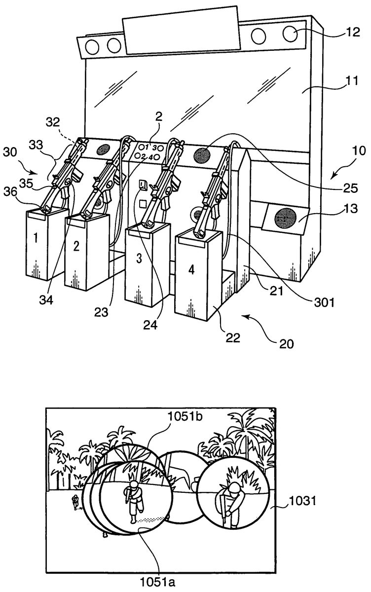
FIG. 1is an overall schematic structural diagram of one embodiment in which the video game apparatus of the present invention is applied to a shooting game apparatus. InFIG. 1, the shooting game apparatus comprises a main body housing part10, an operating housing part20which is disposed in front of the main body housing part10, and a plurality of imitation guns30(e. g., four imitation guns30).
The main body housing part10has a substantially solid-rectangular shape, and comprises a display part11as a monitor that extends to the left and right from roughly the center of the front surface. Audio speakers12are disposed on the left and right on the upper part of the display part11, and speakers13used for audio output, and especially to output sounds that create pressure such as heavy and low sounds or the like, are disposed on the left and right on the lower part of the display part11. A CRT, liquid crystal screen, plasma display or organic EL display can be used as the display part11. Alternatively, a universally known projector or liquid crystal projector may be used.
The operating housing part20comprises an operating part21with a solid-rectangular shape (long in the lateral direction) which has a specified height, preferably a height that is substantially the same height as the lower-end position of the display part11, and four gun mounting stands22that are disposed on the left and right with a lower attitude. On the operating panel2, four start buttons23are disposed on the upper part of the left-right central position together with discriminating symbols (the numerals “1”, “2”, “3” and “4” in the present embodiment), and an insertion slot24into which a specified number of coins are inserted in order to obtain permission to play the game is disposed in the lower part. The respective discriminating symbols assigned to the start buttons23correspond to the four gun mounting stands22. A control part100(seeFIG. 3) which controls the overall action of the present shooting game is disposed inside the main body housing part10. The control part100(FIG. 3) performs processing that associates the start buttons23and imitation guns30by means of the discriminating symbols.
Furthermore, although this is not shown inFIG. 1, an infrared camera40(seeFIG. 3) is disposed (in a configuration which is such that the entire screen of the display part11is the visual field of this camera) in a central position on the upper part of the operating part21on the front side facing the display part11. The installation position of the infrared camera40is not limited to the side of the operating part21; as long as this position allows viewing of the screen of the display part11, this position may be located on a specified member other than the main body housing part10or operating part21. Furthermore, in cases where the display part11comprises a projector, and a semi-transparent projection screen is used, the infrared camera40may be disposed so that the screen is viewed from the inside of the main body housing part10, i. e., from the back side of the projection screen.
FIG. 2shows structural diagrams of the imitation guns, withFIG. 2Abeing an overall perspective view,FIG. 2Bbeing a side view,FIG. 2Cbeing a view of the attitude used to sight through the scope, andFIG. 2Dbeing a view of the ordinary attitude. InFIG. 2, there are four imitation guns30which have the same shape and function. Each imitation gun30is connected to the operating part20via a cable301. Each cable301contains a power supply line and signal line, and also functions to prevent theft of the imitation gun30. The imitation guns30model the general structure of a rifle with a gun body part, a gun barrel part, a shoulder stock part and a trigger part. A laser light emitter32(seeFIG. 3) which emits laser light in the infrared wavelength band toward the front of the gun muzzle is contained as light projecting means inside each gun muzzle part. An aiming device33is disposed on the upper surface of the gun body. The laser light emitters32and infrared camera40respectively constitute position detection means, and position designating means are constituted by the laser light emitters32and infrared camera40.
A trigger34modeling an actual trigger is disposed on the lower part of the gun body part of each imitation gun30, and a trigger switch341(seeFIG. 3) which is switched on in response to a pulling action on the trigger34is contained in the gun body part. The triggering operation is detected by this trigger switch341, and processing is performed as a virtual shooting operation. Furthermore, an ocular sensor35is disposed in the position where the eye used to aim the aiming device33is placed, and a shoulder sensor36which detects the contact of the shoulder is disposed on the shoulder stock part. Proximity sensors such as photo-sensors, dielectric sensors or the like may be used as the ocular sensor35and shoulder sensor36; alternatively, mechanical switches may also be used. As is shown inFIG. 2C, in the attitude in which aiming is performed via the scope, the ocular sensor35contacts the cheek of the player PL, and the shoulder sensor36contacts the shoulder of the player PL; as a result, the fact that the player PL is aiming via the scope is detected. Furthermore, as is shown inFIG. 2D, in the attitude in which the gun is ordinarily held, the shoulder sensor36contacts the shoulder of the player PL, and the ocular sensor35is switched off; as a result, it is detected that the player PL is holding the gun in an ordinary attitude. Furthermore, the ocular sensor35and shoulder sensor36are constructed in order to provide judgement information to the player actin detection part (described later). The player action detection part preferably performs processing with a scope display request (described later) indicated when the ocular sensor35and shoulder sensor36are simultaneously switched on; in the present embodiment, scope mark images are displayed within the gam image displayed on the display part11(as will be described later).
For example, in the game system described in Japanese Patent Application Laid-Open No. 2001-286678, a pad-form game controller is used when the positions that display the scope are instructed; accordingly, in shooting, there is little actual feeling of aiming at a target while sighting through a scope, so that there are limits to realizing a feeling of reality as a shooting game. In the present construction, however, when the players aim the imitation guns30, scope images are displayed on the screen G1. Specifically, when the players aim the imitation guns30, the players can observe scope images that freely move across the screen G1while the players observe this screen G1. Accordingly, the players can realistically experience the feeling of aiming at a target while holding the gun and sighting through the scope, so that the interest of the game as a shooting game is increased. Furthermore, the laser light emitters32may have a configuration in which these emitters are switched on during the duration of the game, or a configuration in which these emitters are switched on only when the triggers34are operated (i. e., pulled at least half-way, in a configuration using a sensor structure that can discriminate between the half-pulled state and fully pulled state of the trigger34).
The infrared camera40has the screen of the display part11as a visual field frame, and detects light in the infrared wavelength band. This camera40is used to allow imaging of the spot light (invisible to the players PL) that is emitted from the imitation guns30and that reaches the screen of the display part11, and to obtain the coordinates of the imaging positions of the spot light on the screen by conducting the acquired images to the control part100(seeFIG. 3). Specifically, positions in the longitudinal and lateral directions on the screen of the display part11and longitudinal and lateral arrangement (coordinate) positions of the CCD elements that are the imaging elements constituting the infrared camera40are caused to correspond as coordinates, and the positions on the display part11are obtained from the coordinates of the CCD elements imaging the spot light. Furthermore, since spot lights from a plurality of imitation guns30(four guns in the present embodiment) are present, the spot lights from the respective imitation guns30must be discriminated from each other when detected. This point will be described with respect to the synchronization processing part108of the control part100(described later). Furthermore, it would also be possible to detect movement of the imitation guns30by the players PL by disposing an acceleration sensor or a movement sensor37using a piezoelectric element (seeFIG. 3) in an appropriate location, e. g., near the gun muzzle, in each imitation gun30.
FIG. 3is a block construction diagram of the present shooting game apparatus. The present shooting game apparatus comprises a control part100that has a microcomputer or the like, and also comprises a ROM120that accommodates various types of data required for game processing, such as game images, game programs, audio data such as effect sounds or the like, and other data, and a RAM130that temporarily holds data during processing. The recording medium in which game programs and the like are stored is not limited to a ROM120; various types of memories can be used. Furthermore, a configuration may also be used in which required types of data are provided by installing game programs or the like in this recording medium from the outside, or by mounting a recording medium in which such data has been installed in the present apparatus. The game images are three-dimensional images in the present embodiment; various types of objects such as back ground images, enemy characters and other objects (e. g., objects for the display of proximate explosions that portray the landing of shells in cases where the shooting misses) are created using required numbers of polygons and textures.
The trigger switches341, ocular sensors35, shoulder sensors36and laser light emitters32of the four imitation guns30are connected to the control part100via the cables301. The control part100is devised so that this control part can discriminate which of the imitation guns30is the origin of the detection signals from the trigger switches341, ocular sensors35and shoulder sensors36, and so that laser light emission instructions can be output to specified imitation guns30. The coin sensor241detects the insertion of a specified number of coins into the insertion slot24.
The display RAM11ahas a memory capacity that stores the game images displayed on the display part11; the memory contents are repeatedly updated at specified intervals, e. g., each 1/60 of a second, and are read out to the display part11at this time.
The control part100comprises an internal timer101, and also comprises the following function executing parts. The gram progression processing part102receives respective operations and detection signals from the respective imitation guns30, and controls the progression of the gam in accordance with a game program stored in the ROM120. In the present embodiment, the system is devised so that other players PL can participate in the game while the game is in progress. When the insertion of coins is detected by the coin sensor241, and a signal indicating that a specified start button23has been depressed is input, the imitation gun30corresponding to this start button23is placed in an operable state, so that participation in the same game is allowed. The background image display processing part103displays the game image from the virtual viewpoint of the camera on the display part11as shown on the screen G1inFIG. 4.
The scope display determining part104preferably instructs the display of images of scope marks (described later) corresponding to the imitation guns30when the ocular sensors35and shoulder sensors36of the imitation guns30are simultaneously on. Furthermore, the scope display determining part104may also display images of scope marks when either the ocular sensors35or shoulder sensors36of the imitation guns30are in an “on” state.
The scope image display processing part105performs display processing of the scope images corresponding to the respective imitation guns30, e. g., as shown inFIG. 4.
Specifically, using the coordinates of the spot lights at the points in time at which the trigger “on” signals are generated as a reference, the scope image display processing part105performs processing in which a small screen G2with a size having a proportional screen angle of θB corresponding to the preset scope magnification relative to the screen angle of θA that is obtained when the entire screen G1is viewed from the virtual viewpoint of the camera is specified, and a screen G3(scope magnification=θA/θB) is obtained in which the image data contained in the abovementioned screen G2is read out from the ROM120and recreated with the original drawn screen angle of θA (i. e., image drawing processing is re-executed). If this is done, then an image G3corresponding to an enlarged image of the image G2is obtained. Furthermore, the scope image display processing part105performs processing in which the image of the screen G1is first expanded in the display RAM11a, and an image with a specified shape, e. g., a circular display frame with a specified diameter (only the inside of the frame is transparent) is superimposed on the center of the screen G3, and this display frame and the image of the screen G3positioned in the transparent portion inside the frame are overwritten on the display RAM11awith the center of the display frame matched to the coordinates (e. g., coordinate points) of the spot light, so that the scope image is displayed superimposed on the screen G1in the display pat11.
FIG. 5shows screen diagrams that illustrate examples of game screens, withFIG. 5Ashowing a screen with no scope display, andFIG. 5Bshowing a screen with a scope display. InFIG. 5A, one enemy character AM1is drawn in one location of the background image1031, and when the spot light from one of the imitation guns30strikes this position, a scope mark1051with a circular frame is displayed in this position, and a scope image1052(referred to as enlarged corresponding image or referred to as enlarged image) which is enlarged (for example) by a method described later is displayed inside this scope mark1051, as shown inFIG. 5B. Specifically, the scope image display processing part105functions as an enlarged corresponding image display part in the present invention.
Furthermore, the scope image display processing part105continuously displays scope images on the screen G1while the display of scope mark images is instructed by the scope display determining part104. Specifically, the scope images continue to be displayed in accordance with the imitation guns30while the ocular sensors35and shoulder sensors36of the imitation guns30are simultaneously on, and in cases where the orientation of one of the imitation guns30varies during this period so that the spot light moves, the position instructed by the imitation gun30varies with the scope image displayed “as is”, so that to the player, the scope image moves across the screen G1in accordance with the orientation of the imitation gun30. As a result of this construction, the players can observe the screen G1while aiming the imitation guns30, and can simultaneously observe the scope images that move freely across the screen G1; accordingly, the players can realistically experience a sensation of aiming at a target while holding the gun and sighting through the scope. Thus, the interest of the game as a shooting game is increased.
Furthermore, in cases where scope marks1051corresponding to a plurality of imitation guns30are in close proximity, and overlap with each other, the scope image display processing pat105performs display precedence imaging (described below).
The shooting judgement part106determines whether or not the triggers34of the model guns30have been pulled so that the trigger switches341are switched on. The hit judgement pat107controls the display coordinates of the respective object images including the enemy characters AM displayed on the display part11, reads the coordinates of the illumination positions of the spot lights from the imitation guns30at the points in time at which trigger “on” signals are output, and performs processing that judges a “hit” in cases where these coordinates coincide with the display coordinates of an enemy character AM, and a “miss” in cases where these coordinates do not coincide. Furthermore, the background image display processing part103calculates the tracks along which the bullets fired from the player side fly through space, and performs a display depicting a “hit” (e. g., erasure of the enemy character AM from the image) in the case of a “hit”, or a display depicting a proximate explosion or the like for the position where the bullet lands in the case of a “miss”.
In the present embodiment, the synchronization processing part108performs processing used to specify which of a maximum of four laser light emitters32is the originating laser emitter32of each spot light on the screen of the display part11. Specifically, the synchronization processing part108causes the laser light emitters32of the respective imitation guns30to perform a light emitting action for a specified period (e. g., 4 times the period of the imaging operation of the infrared camera40), and with the respective phases shifted by ¼ each, for only one period, i. e., in order one at a time. If this is done, then position detection which makes it possible to discriminate (i. e., by timing control) the spot light from each laser light emitter32can be performed for each imaging operation of the infrared camera40. Alternatively, each light emitting operation may be repeated with a period that extends over a plurality of periods of the imaging operation, in a form in which the timing is respectively shifted by an amount equal to the imaging period.
The game score control part109receives trigger “on” signals from the respective imitation guns30, and evaluates the ability of the players operating the respective imitation guns30by converting this ability into numerical values with consideration given to the number of hits (or hit rate) on enemy characters appearing in the game image, the game time controlled by an internal timer101and the like; thus, this part functions as play status evaluation means. The life control part110controls the life that constitutes the game points or scores of the players in the game. For example, the life increases when a shot hits an enemy character, and decreases when the player is hit by an attack from an enemy character. For example, the presence or absence of a hit during an attack by an enemy character can be judged using various types of information such as the relationship between the left-right trajectory of shots from enemy characters and the installation positions of the gun mounting stands22, indication as to whether or not the imitation guns30are in the attack mode (with triggers34pulled), indication as to whether or not the scope display is in use, and the like. Furthermore, in the present game, the system is devised so that if the life is lowered to a specified value, e. g., a value of zero, during the gam, the game is forcibly ended by the game progression processing part102.
The movement status monitoring part111used as movement status monitoring means inputs over time (i. e., periodically) the coordinate positions of the spot lights obtained by the scope image display processing part105from the images acquired by the infrared camera40during scope display, monitors these coordinate positions as the movement histories of the designated positions, and in particular calculates the amounts of movement. Furthermore, the movement status monitoring part111may also be devised so that this part monitors the movements of the imitation guns30themselves from the detection signals of movement sensors37installed as necessary.
The game progression status judgement part112used as game progression status judgement means inputs the game status determined by the game progression processing part102, and judges the progression of the game, game scene and (in cases where the game is constructed from a plurality of stages) the stage of the game.
The player action detection part113used as player action detection means detects the actions of the players, i. e., the attitude in which the imitation guns30are held, and whether or not the players show a body attitude of aiming the guns. In regard to the detection of the attitude in which the imitation guns30are held, this can be detected as described above according to whether the ocular sensors35and shoulder sensors36of the imitation guns30are simultaneously on (seeFIG. 2C), or whether only the shoulder sensors36are on (seeFIG. 2D). Furthermore, in the cases of bothFIG. 2CandFIG. 2D, it is assumed that scope images are being displayed. Alternatively, it would also be possible to install an imaging device in an appropriate location on the main body housing part10, and to detect the attitude of the imitation guns30held by the players directly by imaging the players. In this case, the question of whether or not the players are showing an aiming body attitude can be determined from the presence or absence of movements of the players body, e. g., amount of movement, speed of movement, frequency of movement and the like, in addition to the attitude in which the imitation guns30are held by the players, and/or by considering the “on” and “off” signals of the ocular sensors35and shoulder sensors36of the imitation guns30as well. Instead of an imaging device, it would also be possible to use a configuration in which an ultrasonic transmitter is installed in an appropriate location above the heads of the players, ultrasonic receivers are installed on the left and right sides, ultrasonic waves are transmitted downward from the transmitter, reflected by the heads of the players and received by the respective receivers, and the heights of the players heads and movements to the left and right are detected utilizing the propagation times of the received ultrasonic pulses from transmission to reception, and the differences in these times.
The display precedence setting part114sets the scope image1052that is preferentially written as overwriting in cases where the scope marks1051used as display frames corresponding to the respective imitation guns30overlap as a result of proximate positions within the screen being indicated by the respective imitation guns30. For example, inFIG. 6,FIG. 6Ashows a state in which two scope marks1051are separated to the left and right,FIG. 6Bshows a state in which the right-side scope mark1051has moved to the left, andFIG. 6Cshows a state in which the right-side scope mark1051has covered the scope image1052inside the left-side scope mark1051which has remained stationary on the original left side aiming at an enemy character AM1, so that this right-side scope mark1051impedes shooting. Accordingly, in cases where two or more scope marks1051are in close proximity, and especially in cases where these scope marks overlap, the question of how to display the overlapping region becomes a problem. Consequently, the display precedence in cases where two or more scope marks1051are in close proximity, and in cases where these scope marks overlap, is set according to a specified rule. In this rule, the coordinates of the respective spot lights obtained as designated positions by the detection of the respective spot lights directed from the respective imitation guns30and reaching the surface of the screen (as obtained by the scope image display processing part105) are taken as the scope coordinates (e. g., the centers of the scope marks1051), and the distances between these scope coordinates, the amounts of movement of the scope marks1051obtained by the movement status monitoring part111(and/or the amounts of movement of the imitation guns30detected by movement sensors37), the play evaluation histories of the respective imitation guns30up to this point in time obtained by the game score processing part109, the game scene status or the like obtained by the game progression status judgement part112, and the status of player actions obtained by the player action detection part113, are used as judgement elements. The respective configurations of the display precedence will be illustrated using flow charts and the like described later.
The scope image display processing part105successively writes the respectively prepared scope images into the display RAM11ain accordance with the set display precedence, i. e., in the order of lower display precedence, so that in the case of overlapping regions, the scope image with the highest display precedence is finally displayed on the display part11(together with the display frame1051in the present embodiment). Furthermore, the scope marks1051are useful in facilitating discrimination of the boundaries between the scope images and the background image, and are used as necessary.
The audio processing part115outputs required sound effects, e. g., effect sounds such as shooting sounds, sounds of landing bullets, hits, proximate explosions and the like, from speakers12,13and25. The system may be devised so that the speakers25handle shooting sounds of the players, the speakers122handle attack sounds from the enemy characters, and the speakers13handle effect sounds such as the sounds of landing bullets, hits, proximate explosions and the like.
FIG. 7is a basic flow chart of the game progression routine. When the power supply is switched on in the game apparatus, a specified demonstration screen is displayed (step ST1), and the system waits for the game (step ST3). Then, when coins are inserted, and at least one of the four game buttons23is operated, a signal from the I/O input of the control part100is detected (step ST5), and the system proceeds to game processing (step ST7). Here, if the life value is zero or the like, the game is over at an intermediate point; if this is not so, then the preset stage is cleared, the system successively proceeds to subsequent stages, and a judgement is made as to whether or not the final stage has been reached (step ST9). Then, when the final stage is cleared, an ending demonstration screen, e. g., a screen showing the game results such as the score or the like, is displayed (step ST11). The system then proceeds to the game over screen (step ST13), and the present game is ended.
Furthermore,FIG. 8shows the “game processing” subroutine in one stage of step ST7. InFIG. 8, a judgement is first made as to whether or not the lives of all of the players have been eliminated (step ST21). If this is so, the system returns as “game over”. If at least one player has remaining life, the display processing of the game image is continued (step ST23), i. e., progression of the game is executed, and a judgement is made as to whether or not the stage has been cleared (step ST25). If the stage has not been cleared, the processing returns to step ST21, and the game is continued; if the stage has been cleared, the system returns as “stage cleared”.
FIG. 9shows the “game image display” processing subroutine of step ST23. First, inFIG. 9, the background image1031is displayed, i. e., writing into the display RAM11ais performed (step ST31). Then, the display precedence is calculated (step ST33). If the calculation of the display precedence has been completed for all of the players (YES in step ST35), rearrangement into the order of decreasing display precedence is performed (step ST37), and processing involving the input of I/O input information and the like is then performed in the rearranged order (step ST39). Then, a judgement is made from the input data as to whether or not there has been a request for scope display (step ST41). In the case of players who have not requested scope display, the processing proceeds to step ST45, while in the case of players who have requested scope display, the preparation of scope marks1051and scope images1052required for scope display is performed, and these are written into the display RAM11a(step ST43). Next, a judgement is made as to whether or not all scope display processing has been completed (step ST45); if scope display processing remains, the processing returns to step ST39, and similar processing is performed in order. Then, when all of the scope display processing has been completed, the processing exits this flow.
FIG. 10shows a modification ofFIG. 9, and is a flow chart used in a case where the constituent part that writes the scope images into the display RAM11ais constructed from hardware that has a display precedence drawing function. In this flow chart, after the calculation of the display precedence similar to that of steps ST31and ST32has been performed for all of the players (step ST51), a judgment is made as to whether or not there has been a request for scope display (step ST53). In the case of players who have not requested scope display, the processing proceeds to step ST57, while in the case of players who have requested scope display, the information on display precedence obtained by calculation is sent to the hardware and written (step ST55). Next, a judgement is made as to whether or not all of the scope display processing has been completed (step ST57). If scope display processing remains, the processing returns to step ST53, and similar processing is performed in order; then, when all of the scope display processing has been completed, the processing exits this flow.
FIG. 11shows the “display precedence calculation” processing in step ST33, andFIG. 12shows screen diagrams used to illustrate the scope display according to the calculation processing shown inFIG. 11. In the flow chart shown inFIG. 11, a memory part that stores n sets of scope coordinates for the respective spot lights obtained in accordance with the imaging period of the infrared camera40is provided inside the RAM130. In step ST61, each time that the most recent scope coordinates are obtained by the imaging operation of the infrared camera40, these scope coordinates are stored as updated coordinates in place of the oldest scope coordinates. Next, the amount of movement for the number of histories (elapsed time corresponding to n periods of the imaging operation) is calculated from the scope coordinate histories (step ST63).
For example, the amount of movement, i. e., the display precedence, is calculated using the following equation.
Display precedence ValueA=[Σk=1˜n(|Coordinates ofKth-History−Coordinates of (k−1)th-History|)]/n[Equation 1]
Where “Σk=1˜n”indicates mathematical notation of summation with k starting with a value 1 and incremented by one until k=value “n”.
Equation 1 always focuses on the amounts of movement of the most recent n sets of scope coordinates, and determines the display precedence as a higher display precedence as the overall sum of the amounts of movement is smaller. As a result, the scope mark1051aof a player Pa who is pointing the imitation gun30at a specified position on the screen, e. g., who is aiming at a specified enemy character, as shown inFIG. 12A, can be preferentially displayed as shown inFIG. 12Cover the scope mark1051bof a player Pb (with a large amount of movement) who is viewed as not yet having fixed his aim (this scope mark1051bhaving moved to a position that partially overlaps with the scope mark1051aor that more or less coincides with the scope mark1051a) as shown inFIG. 12B.
Furthermore, the arrows shown inFIGS. 12A and 12Bindicate the direction and magnitude of the movements of the scope coordinates. In actuality, the final single scope image in the direction of each arrow is displayed; here, however, past scope images are also shown for convenience in describing the movement history.
Furthermore, the display precedence setting part114may also apply weighting relating to the setting of the display precedence to the most recent movement history among the movement histories that are monitored. In this setting of the display precedence, weighting can be applied the newest (most recent) movement amount by performing calculations as shown in Equation 2.
Display Precedence ValueA=(most recent precedence valueA)X(n−1)/n+(|most recent history coordinates−previous history coordinates|) [Equation 2]
As a result, a more recent movement history can be applied to the display precedence, i. e., the response (reaction) speed for the display precedence can be increased, as the movement history is more recent. Furthermore, the method used to apply weighting to the mores recent amount of movement is not limited to Equation 2; the system may also be devised so that specified separate weighting coefficients are applied (weighting is applied) to a plurality of the most recent calculated amounts of movement.
FIG. 13shows a subroutine which illustrates another embodiment of the calculation of the display precedence. InFIG. 13, for example, the display precedence corresponding to the evaluation of the play is calculated from specified parameters (step ST71). The number of killed enemy characters (e. g., the score), or the remaining life of the players, can be used as the abovementioned specified parameters. Specifically, the scope images of players who have killed larger numbers of enemy characters (players with a higher score) or players with a larger remaining life value, are preferentially displayed.
FIG. 14shows a subroutine which illustrates still another embodiment of the calculation of the display precedence. InFIG. 14, the current display precedence is calculated from a list of preset conditions (step S81). For example, a configuration in which a specified order is set for the four players (four imitation guns30) in each scene of the stage, a configuration in which players (imitation guns30) that have specified items are given preference, or a configuration in which the display precedence is set beforehand in accordance with the elapsed time of the game, is conceivable as the abovementioned list of conditions. Alternatively, these configurations may be appropriately combined. For example, the system may be devised so that the game progression processing part102causes various items to appear (i. e., to be displayed on the display part11) in an irregular manner during the progression of the game, and these items are characteristically applied to (associated with) players whose shooting has scored hits on these items. Furthermore, the system may also be devised so that the game progression processing part102increases the performance of the imitation guns30of the players endowed with these items, e. g., so that the game progression processing part102increases the performance in accordance with the respective items by increasing the destructive force of the guns, increasing the amount of ammunition that is loaded in the guns, increasing the size of the frame of the scope mark1051, or increasing the display magnification. Specifically, relative variability with respect to the difficulty of the game play can be introduced in accordance with item acquisition, thus making a more interesting game.
Furthermore, as still another embodiment of the calculation of the display precedence, the actions of the players may be considered. In this case, the display precedence is set in accordance with the actions of the players detected by the player action detection part113. For example, in cases where a player has placed both the ocular sensor35and the shoulder sensor36of the imitation gun in an “on” state, i. e., in cases where this player is holding the imitation gun30in the attitude shown inFIG. 2C, it is judged that this player has fixed his aim on a specified target while closely observing the scope image, and the display precedence setting part114sets the display precedence of the scope image corresponding to this imitation gun at a high value. Furthermore, for example, in cases where a player has placed the ocular sensor35of his imitation gun in an “off” state, i. e., in cases where this player is holding the imitation gun30in the attitude shown inFIG. 2D, it is judged that the player has not fixed his aim on a specified target, and does not consider the scope image to be important; accordingly, the display precedence setting part114sets a lower display precedence for the scope image corresponding to this imitation gun than the precedence that is set when both the ocular sensor35and shoulder sensor36are in an “on” state. Furthermore, for example, in cases where a player has placed both the ocular sensor35and shoulder sensor36of his imitation gun30in an “off” state, it is judged that the player has not yet held the imitation gun30in an aiming attitude, and the display precedence setting part114sets the lowest display precedence for the scope image corresponding to this imitation gun.
Furthermore, the display precedence setting part114can also set a precedence that is a composite of respective precedence values set on the basis of information obtained from the movement status evaluation part, game progression status judgement part and player action detection part. Furthermore, the precedence among the respective precedence values may be arbitrarily set.
FIGS. 15 through 20are diagrams which are used to illustrate still another embodiment relating to the preferential display of scope images in the display precedence setting part114and scope image display processing part105. In this embodiment, the game progression processing part102, scope image display processing part105and display precedence setting part114shown inFIG. 3also have the following functions.
Specifically, the game progression processing part102performs a function that outputs data indicating the number of depressed start buttons23, i. e., the number of participants m, to the control part100. Furthermore, the scope image display processing part105performs display processing of scope images corresponding to the respective imitation guns30, forms and displays scope marks constituting circular display frames that have a diameter (scope size s) that will be described later in some regions of the display screen of the background image, prepares scope images which are images that are enlarged by a specified magnification with respect to the background image inside the abovementioned frames, and writes and displays these scope images.
The display precedence setting part114makes a judgement as to whether the mutual relationships of the arrival coordinates of the spot lights on the screen of the display part11are within a specified (first) proximity range, or within a second proximity range in which the display frames are in such close proximity that at least portions of the display frames overlap. Outside the first proximity range, the display precedence setting part114sets an ordinary size as the size of the display frame (scope image); on the other hand, within the first to second range, the display precedence setting part114sets a specified size that is smaller than the ordinary size in accordance with the abovementioned display precedence, and within the second proximity range, the display precedence setting part114causes a display to be performed in accordance with the display precedence as in the abovementioned embodiment. Specifically, the scope image display processing part105calculates and sets the diameter of the scope mark1051as a scope size s that is smaller than the ordinary size, so that the probability of the scope marks1051corresponding to the respective imitation guns30overlapping as a result of the respective guns30pointing to proximate positions within the screen is reduced. For example, inFIG. 6,FIG. 6Ashows a state in which two scope marks1051are separated to the left and right,FIG. 6Bshows a state in which the right-side scope mark1051has moved to the left side, andFIG. 6Cshows a state in which the right-side scope mark1051has covered the scope image1052inside the left-side scope mark1051which has remained stationary on the original left side aiming at an enemy character AM1, so that this right-side scope mark1051impedes shooting.
In this case, the overlapping of the right-side scope mark1051and left-side scope mark1051can be avoided, or this overlapping can be reduced, by reducing the diameter of the scope marks1051. However, in cases where the diameter of the scope marks1051is unconditionally reduced, the display of the scope images1052inside the scope marks1051is reduced in size; as a result, there is a danger that the ease with which the scope images can be seen by the players will be impaired. Accordingly, the system is devised so that the scope image display processing part105calculates and sets the scope size s according to a specified rule in cases where two or more scope marks1051are displayed. The number of participants m or the distance between the scope marks1051may be utilized as judgement elements in this rule. In cases where the number of participants m is utilized as a judgement element, the display precedence may be set in accordance with the number of persons so that the size becomes successively smaller; alternatively, a configuration may be used in which the size is altered as described above (using first and second proximity ranges) in accordance with the mutual relationships of the respective positions within respective numbers of persons.
From data expressing the number of participants m obtained by the game progression processing part102, the scope image display processing part105sets the scope size s in stages in accordance with the number of participants m, so that this size in increased in cases where the number of participants m is small, and reduced in cases where the number of participants m is large. For example, the correspondence between the number of participants m and the scope size s is stored beforehand in an LUT (look-up table) memory, and the scope image display processing part105determines and sets the scope size s from the number of participants m by referring to this LUT.
Furthermore, for example, a construction may be used in which the scope size s in a case where the scope size s is the maximum scope size, i. e., a case in which the number of participants m is 1, is stored in memory beforehand as the maximum scope size smax, and the scope size is calculated as
s=smax/m
Furthermore, for example, a construction may be used in which the minimum scope size s required in order for the players to recognize the scope images1052and play the game is stored in memory beforehand as the minimum scope size smin, and the scope size s is set at the minimum scope size sminregardless of the number of participants m in cases where the scope size s obtained by the scope image display processing part105falls below the minimum scope size smin. As a result, in cases where the number of participants is large, the scope size s is set at a small size by the scope image display processing part105. Furthermore, since scope marks1051whose diameters have the abovementioned set scope size s are displayed by the scope image display processing part105, and since the scope images1052are written as overwriting and displayed inside these scope marks1051, the scope images1052are displayed with a small size. Accordingly, there is little overlapping display of scope images1052.
On the other hand, in cases where the number of participants m is small, the scope size s is set at a large value by the display precedence setting part114. Furthermore, since the scope marks1051are set at a large size by the scope image display processing part105, and since the scope images1052are written as overwriting and displayed inside the scope marks1051, the scope images1052are displayed with a large size. Accordingly, the scope images1052are displayed so that these images can easily be seen by the players.
Furthermore, in cases where the scope size s is set in accordance with the distance between the respective scope marks1051, the scope image display processing part105calculates the distances between the respective scope marks1051from the coordinates of the respective spot lights obtained by the infrared camera40, i. e., the coordinates of the positions at which the centers of the respective scope marks1051are displayed, and determines the shortest distance among these calculated distances as the minimum distance lmin. Furthermore, the scope image display processing part105may also have a construction in which the distance at which the diameters of the scope marks1051are displayed as the smallest values, i. e., the distance at which the minimum scope size sminis set as the scope size s, is stored beforehand in memory as the shortest distance of scope size variation M, and the scope size s is calculated from the minimum scope size smin, minimum distance lminand shortest distance of scope size variation M using the following calculation formula:
s=smin×(lmin/M)
Furthermore, a construction may also be used in which the average value of the abovementioned calculated distances between the respective scope marks1051is determined as the average distance laveinstead of the minimum distance lmin, and the scope size s is calculated as
s=smin×(lave/M)
from the minimum scope size smin, average distance laveand shortest distance of scope size variation M.
Furthermore, the scope image display processing part105may also have a construction that calculates the scope size s using both the number of participants m and the distances between the respective scope marks1051.
FIG. 15shows another subroutine of the “game image display” processing of step ST23. InFIG. 15, processing of the display of the background image1031, i. e., writing into the display RAM11a, is first performed (step ST131). Then, the calculation and setting of the scope size s are performed (step ST133). Then, processing such as the input of I/O input information and the like is performed, and a judgement is made from the input data as to whether or not there is a request for scope display (step ST135). In the case of players who have not requested scope display, the processing proceeds to step ST39; in the case of players who have requested scope display, scope marks1051and scope images1052used for scope display are prepared so that the image size has the diameter of the abovementioned set scope size s, and this data is written as overwriting into the display RAM11a(step ST137). Next, a judgement is made as to whether or not all of the scope display processing has been completed (step ST139), and if processing remains, the subroutine returns to step ST135, and similar processing is performed in order. When all of the scope display processing has been completed, the processing exits this flow.
FIG. 16shows the subroutine of the “scope size s calculation and setting” processing in step ST133. InFIG. 16, the number of participants m obtained by the game progression processing part102is first acquired by the scope image display processing part105(step ST141), and a size corresponding to the acquired number of participants m is set as the scope size s in the abovementioned LUT by the display precedence setting part114(step ST143). As a result, a large value is set as the scope size s in cases where the number of participants m is small, and a small value is set as the scope size s in cases where the number of participants m is large. Then, the processing returns.
FIG. 17shows screen diagrams used to illustrate the scope display in cases where the scope size s is set in accordance with the number of participants m.FIG. 17Ashows the display of the scope mark1051aand scope image1052ain a case where the number of participants m is 1,FIG. 17Bshows the display of the scope marks1051band scope images1052bin a case where the number of participants m is 2, andFIG. 17Cshows the display of the scope marks1051cand scope images1052cin a case where the number of participants m is 3.
InFIG. 17B, since the number of participants m is greater than in the case ofFIG. 17A, the scope size s is set at a smaller value than in the case ofFIG. 17A; accordingly, the scope marks1051bare displayed with a smaller diameter than the scope mark1051a. As a result, inFIG. 17B, the two scope marks1051band scope images1052bare displayed with a smaller size than in a case where the two scope marks1051bare displayed with the same diameter as the scope mark1051aregardless of the number of participants m. Accordingly, there is little possibility that the images will overlap with each other. Similarly, inFIG. 17C, the three scope marks1051cand scope images1052care displayed with a smaller size than in a case where the three scope marks1051bare displayed with the same diameter as the scope mark1051a; accordingly, there is little possibility that the images will overlap with each other.
FIG. 18shows a subroutine which illustrates still another embodiment of the “scope size s calculation and setting” processing in step ST133. First, in step ST151, a sufficiently large numerical value, e. g., a numerical value indicating the length of the diagonal line of the display part11, is substituted for the minimum distance lmin, which is the variable used to accommodate the minimum distance among the distances between the respective scope marks1051, so that the minimum distance lminis initialized, by the scope image display processing part105.
Next, the distance l between a certain scope mark1051and another scope mark1051is calculated by the scope image display processing part105from the coordinates of the respective spot lights obtained by the infrared camera40, i. e., the coordinates of the positions where the centers of the respective scope marks1051are displayed (step ST153), and the minimum distance lminand distance l are compared (step ST155). In cases where the minimum distance lminis smaller than the distance l, the processing proceeds to step ST159; on the other hand, in cases where the minimum distance lminis greater than the distance l, the distance l is substituted for the minimum distance lmin(step ST157), and the processing proceeds to step ST159.
Next, a check is made by the scope image display processing part105as to whether or not distances have been calculated between each scope mark1051and all of the other scope marks1051for all of the scope marks1051displayed (step ST159). If distances remain to be calculated, the processing returns to step ST153, and the processing of steps ST153through ST159is performed for the new distances between scope marks1051. If distances between all of the scope marks1051have been calculated, the processing returns to step ST161. As a result, the shortest distance among the distances between the respective scope marks1051is determined as the minimum distance lmin.
Next, the minimum distance lminand the shortest distance of scope size variation M are compared by the scope image display processing part105(step ST161). In cases where the minimum distance lminis greater than the shortest distance of scope size variation M, the processing proceeds to step ST165; on the other hand, in cases where the minimum distance lminis smaller than the shortest distance of scope size variation M, the shortest distance of scope size variation M is substituted for the minimum distance lmin(step ST163), and the processing proceeds to step ST165. Since the minimum distance lmincorresponds to the minimum scope size smin, the scope size s can be prevented from becoming smaller than the minimum scope size sminby the processing of step ST161and step ST163.
Next, in step ST165, the scope size s is calculated and set by the scope image display processing part105from the minimum scope size smin, minimum distance lminand shortest distance of scope size variation M using the calculation formula
s=smin×(lmin/M),
the “scope size s calculation and setting” processing is completed, and the processing returns.
FIG. 19shows screen diagrams used to illustrate the scope display in cases where the scope size s is set in accordance with the distance between the scope marks1051.FIG. 19Ashows the display of the scope marks1051aand scope images1052ain a case where the distance between two displayed scope marks1051ais large, andFIG. 19Bshows the display of the scope marks1051band scope images1052bin a case where the distance between two displayed scope marks1051bis small.
InFIG. 19B, since the distance between the scope marks is smaller than in the case ofFIG. 19A, the scope size s is set at a smaller value than in the case ofFIG. 19A; accordingly, the scope marks1051bare displayed with a smaller diameter than the scope marks1051a. As a result, although the scope marks1051bwould overlap with each other if the scope marks1051binFIG. 19Bwere displayed with the same diameter as the scope marks1051a, there is no overlapping of the respective scope marks1051bor scope images1052binFIG. 19B, since the scope marks1051band scope images1052bare displayed with a smaller diameter in accordance with the inter-scope distance.
FIG. 20shows a subroutine which illustrates still another embodiment of the “scope size s calculation and setting” processing in step ST133. InFIG. 20, the number of participants m obtained by the game progression processing part102is first acquired by the scope image display processing part105(step ST171), and a size corresponding to this acquired number of participants m is set by the scope image display processing part105as the standard scope size s1in the abovementioned LUT (step ST173). As a result, a large value is set as the standard scope size s1in cases where the number of participants m is small, and a small value is set as the standard scope size s1in cases where the number of participants m is large.
Next, in step ST175, the minimum distance lminis calculated by the scope image display processing part105using the same processing as in steps ST151through ST163, and the scope size s is calculated and set from the minimum scope size smin, maximum scope size smaxstandard scope size s1, minimum distance lminand shortest distance of scope size variation M using the following calculation formula:
s=smin×(lmin/M)×(s1/smax)
Then, the “scope size s calculation and setting” processing is completed.
Furthermore, the scope image display processing part105may also set the scope size s in association with the display precedence setting part114. In this case, the scope image display processing part105refers to the display precedence calculated and set by the display precedence setting part114using the abovementioned method, and sets the scope size s at a relatively large value in the case of a high display precedence, and at a relatively small value in the case of a slow display precedence.
Furthermore, it is also desirable to take into account the positional relationships (distances) between displayed scope marks in the setting of the scope size s in association with the display precedence setting part114. For example, in cases where scope images are close to each other, processing which reduces the scope size s of the scope image with a lower precedence is performed. Furthermore, in this case as well, the scope image display processing part105displays scope images based on the precedence set by the display precedence setting part114when scope images overlap with each other.
Furthermore,FIG. 21shows diagrams that illustrate the display conditions in a case where the mutually overlapping regions are uniformly divided when the scope images1051of two players overlap. In this case, an enemy character AM1is displayed in the scope image1051a, and an enemy character AM2is displayed in the scope image1051b. As is shown inFIG. 21A, instead of using a method in which the portion1053where both scopes overlap is preferentially assigned to one scope or the other, processing is performed which respectively divides this portion along a line segment connecting the intersection points of the scope mark1051aand scope mark1051b(FIG. 21B). If this is done, the divided portions are always equal; accordingly, neither player has a display precedence, and the problem of one player suffering from a disadvantage is ameliorated.
Furthermore, the present invention may also use the following modified configurations.
(1) A desirable condition for scope display was set as a simultaneous “on state” of both the ocular sensor35and shoulder sensor36. However, the present invention is not limited to this; it would also be possible to provide a scope display when only one sensor, e. g., the ocular sensor35, is “on”, or to use a configuration in which a scope display is provided during the game without conditions.
(2) The present invention was described as a shooting game. However, the present invention is not limited to this; the present invention can be applied to games which are devised so that when appropriate locations on the screen on which the background image is displayed are designated by position designating means, e. g., a plurality of controllers or the like, images of partial regions including these portions are enlarged and displayed, and the game progresses by thus making the background image observable in greater detail.
(3) In the present embodiment, since infrared light is used for position designation, the shooting positions on the screen cannot be directly observed. However, it would also be possible to utilize image processing so that shooting markers are displayed in the detected positions of the spot lights. Alternatively, it would also be possible to use a mode in which positions are designated using visible light in a configuration in which the present game apparatus is installed inside a building.
(4) The synchronization processing part108is not limited to a phase shifting system; some other method may be used. For example, the four laser light emitters32may be assigned individual codes consisting of specified bits, and the light emission can be periodically controlled using these individual codes. For example, if these emitters are defined using 4-bit individual codes, then four types of codes can be prepared by setting the initial and final bits as “high” bits, and realizing the second and third bits as either “high” or “low” bits. If this is done, then the respective spot lights can be displayed in a manner that allows discrimination by causing one bit of light emission to correspond to the imaging period (if there are six imaging periods before and after).
(5) The number of imitation guns is not limited to four; it is sufficient if there are two or more guns.
(6) The method used to create the enlarged images is not limited to the abovementioned embodiment. For example, the scope image display processing part105may be devised so that scope marks1051are set (e. g., in the center) using the coordinates of the spot lights at the points in time at which trigger “on” signals are generated as a reference, and processing is performed so that images of specified regions center on these spot lights that are drawn within these scope marks1051, i. e., images that converted into distances that correspond to a preset display magnification as a scope function, are applied as overwriting or underwriting within the scope marks1051, i. e., to the display RAM11a, by reading out required image data from the ROM120and re-executing image drawing processing (for example, if the display magnification rate is set at 5× in the case of an enemy character AM1(FIG. 4A) that is separated by a distance of 100 m from the virtual camera viewpoint that creates the background image within the game space, then a display image of this enemy character AM1(FIG. 4B) is created so that it appears as though the character is in a position that is separated from the virtual camera viewpoint by a distance of 20 m). Alternatively, the images used as enlarged images may be prepared beforehand, and processing that pastes appropriate corresponding images in accordance with the designated positions may be performed.
(7) As another embodiment of the position designating means, a method may be used in which markers with a configuration having respective length information for two axial directions are provided on the side of the imitation guns30or on the side of the main body housing part10, these markers are imaged by a camera installed on the other side, and the position designating means calculate which positions on the screen of the display part11are designated from the imaging conditions on the side of the acquired images. Alternatively, a method in which the imitation guns are directly imaged by a CCD camera, and the positions and orientations of the imitation guns30and (from such information) the aiming positions on the screen of the display part11are calculated from the acquired images, or (as a simpler configuration) a method in which specified position-specifying marks within the screen (these may be point-form marks) or similar position-specifying marks outside the screen, are displayed by disposition or light emission, these marks are imaged by position designating means, e. g., CCD cameras installed in the gun muzzles on the side of the imitation guns30, and the pointing (designation) directions of the imitation guns30are detected from positional information for the mark images within the acquired images, may also be used. Thus, the position designating means include configurations constructed from a combination of a member that indicates positions and a member that detects these positions, and configurations that perform detection only on one side, as in the case of a CCD camera or ultrasonic transmitter-receiver.
(8) Here, the principle of the method described in (7), in which markers with a configuration having respective length information for two axial directions are provided on the side of the imitation guns30or on the side of the main body housing part10, these markers are imaged by a camera installed on the other side, and the position designating means calculate which positions on the screen of the display part11are designated from the imaging conditions on the side of the acquired images, will be described.
In the position designating means used in this method, one or a specified number of so-called L-shaped markers are displayed in specified positions on the display screen of the display part11, preferably all at equal intervals with two markers being disposed in the vertical direction and three markers being disposed in the horizontal direction (or the reverse of this arrangement), and with one marker being disposed in common at the position of the vertical-horizontal intersection point. Alternatively, one or a specified number of markers comprising L-shaped point-form light sources (e. g., LEDs) with the same shape as that described above are disposed in specified positions in peripheral locations on the display part11. Meanwhile, imaging devices such as CCD cameras or the like are mounted in the gun muzzles of the imitation guns30. Furthermore, in this method, the abovementioned L-shaped markers are imaged by the CCD cameras, and the positions on the screen of the display part11that are pointed at by the gun muzzles are calculated from the imaging conditions of the respective point images with the images that are acquired in this case. Specifically, the position designating means further comprise means that calculate the orientations of the CCD cameras, i. e., the line-of-sight vectors of the gun muzzles, on the basis of information on the dimensions in the axial direction for the positions, amounts of rotation and inclinations of the acquired marker images, and means that calculated the points of intersection of the calculated line-of-sight vectors with the screen of the display part11. By using such a construction, it is possible to calculate the points of intersection of the gun muzzles, i. e., the line-of-sight vectors, with the screen (i. e., the designated positions) from the rotation of the L-shaped markers within the acquired images, and the distances between the respective point images, in accordance with the rotation and inclination of the imitation guns30relative to the screen (Japanese Patent Application No. 2001-242819).
Furthermore, the positions on the screen pointed at by the gun muzzles can be calculated from the images acquired by the CCD cameras even in the case of a positional relationship that is the opposite of that described above, i. e., a relationship in which the abovementioned L-shaped markers comprising point-form light sources are installed in the gun muzzles of the imitation guns30, and CCD cameras are installed in appropriate locations on the periphery of the display part11(Japanese Patent Application No. 2002-36791). The discrimination of a plurality of imitation guns can be accomplished (for example) by varying the light emission timing of the respective markers or by varying the imaging timing of the CCD cameras.
(9) In short, the video game apparatus described as the invention comprising the embodiments shown inFIGS. 15 through 20is a video game apparatus which displays game images on a monitor screen, and allows play by a plurality of players, this video game apparatus comprising position designating means for respectively designating desired positions on the abovementioned monitor screen in accordance with instructions from a plurality of locations, and enlarged image display means for producing enlarged images that correspond to enlarged images of images displayed within specified regions that include the abovementioned designated positions, and displaying the abovementioned enlarged images in specified regions, on the screen of said monitor, having a size which has been set in accordance with the mutual relationship of the abovementioned respective designated positions and/or the number of designated positions. In this case, in regard to the two embodiments shown inFIGS. 15 through 20, processing that alters the size of the scope marks according to the proximity of the designated positions to each other, and processing that alters the size of the scope marks according to the number of players, can be separately executed regardless of whether processing for cases of overlapping scope marks is included or not.
(10) Furthermore, in the abovementioned embodiments, the mutual relationships between positions were described as relative distances between positions. However, the mutual relationships between positions in the present invention are not limited to relative distances between positions. For example, even in cases where the distance relationships between positions designated at a certain timing and positions designated at a different timing are the same, it is conceivable that there may be instances in which information concerning the heights of the respective positions on the game image (i. e., the heights on the monitor screen) differs according to the timing, and instances in which the rates of positional variation over time (i. e., speeds of positional variation) of respective positions are different.
(11) Furthermore, the present applicant has recognized and described here an invention comprising a video game apparatus which encompasses an invention of a configuration devised so that respective enlarged images are displayed on the abovementioned monitor screen in accordance with the mutual relationships between positions, as well as the invention described in (9), and which displays game images on a game screen and allows play by a plurality of players, this video game apparatus comprising position designating means for respectively designating desired positions on the abovementioned monitor screen in accordance with instructions from a plurality of locations, and enlarged image display means for producing enlarged images that correspond to enlarged images of images displayed within specified regions that include the abovementioned designated positions, and displaying the abovementioned enlarged images in accordance with the mutual relationship of the abovementioned respective positions so that the abovementioned designated positions within the abovementioned monitor screen are included.
Summing up the present invention, a video game apparatus which displays game images on a monitor screen and allows play by a plurality of players, comprising position designating means for respectively designating desired positions on the abovementioned monitor screen in accordance with instructions from a plurality of locations, and enlarged corresponding image display means (or referred to as enlarged image display means) for producing enlarged images that correspond to enlarged images of images displayed within specified regions that include the abovementioned designated positions, and displaying the abovementioned enlarged images in accordance with the mutual relationship of the abovementioned respective positions so that the abovementioned designated positions within the abovementioned monitor screen are included.
Another form of the invention relates to a recording medium storing a program which is installed in a computer that is connected to a monitor and a plurality of operating input devices, and which is used to realize a game apparatus that displays game images on the screen of the abovementioned monitor, and that allows play by a plurality of players via the abovementioned operating input devices, wherein the abovementioned plurality of operating input devices are caused to function as position designating means that respectively designate desired positions on the abovementioned game images, and the abovementioned computer is caused to function as position detection means that detect the abovementioned positions designated by each of the abovementioned operating input devices, and as enlarged image display means that produce enlarged images corresponding to enlarged images of images in specified regions including the abovementioned positions detected by the abovementioned position detection means, and that display the abovementioned enlarged images in accordance with the mutual relationships of the abovementioned respective positions so that the abovementioned designated positions within the screen of the abovementioned monitor are included.
Furthermore, another form of the invention relates to an image processing method which displays game images on a monitor screen, comprising the steps of a position designating step in which instructions from a plurality of locations generated by the position indication means are received, and desired positions on the screen of the abovementioned monitor are respectively designated, and an enlarged image display step in which enlarged images corresponding to enlarged images of images displayed within specified regions that include the abovementioned positions instructed by the abovementioned position indication means are produced, and the abovementioned respective enlarged images are displayed in accordance with the mutual relationships between the abovementioned respective positions so that the abovementioned instructed positions within the abovementioned monitor screen are included.
In the abovementioned inventions, a game is played by two or more desired positions on the monitor screen being designated through the position designating means by a plurality of player or the like with respect to the game image that is displayed on the monitor screen. For each of the plurality of positions designated on the monitor screen, an enlarged image corresponding to an image that enlarges the image displayed within a specified region that includes this position is produced by the enlarged image display means. Furthermore, a judgment of the mutual relationships between the respective positions and the like are made. Then, enlarged corresponding images are displayed on the monitor screen in a configuration corresponding to the judged mutual relationships between positions. Specifically, enlarged images are displayed in a configuration that allows mutual influence on the basis of the mutual positional relationships of these images. As a result, a game can be provided in which the game operability is improved by the display of partial enlarged images such as scope displays or the like in a configuration that allows mutual influence for each of a plurality of players on the screen of the monitor on which the game images are displayed, and in which the feeling of pressure and the feeling of actual presence on the scene are high.
In the aforementioned video game apparatus, the abovementioned position designating means may include a plurality of position indication means that can be operated by players, and position detection means that respectively detect the abovementioned instructed positions. In this construction, the position designating means may have an integral configuration or a configuration in which the position indication part and position detection part are separate. Position designation is performed via the operations of the respective players by a plurality of position indication means, and the respective designated positions are detected by the position detection means.
In the aforementioned video game apparatus, the abovementioned position indication means includes light projecting means, and the abovementioned position detection means detect the positions of light reaching the abovementioned monitor screen from the abovementioned light projecting means and obtain the abovementioned positions as coordinates on the abovementioned monitor screen. In this construction, when the (e. g.) laser light reaches the monitor screen illuminated by the light projecting means, the position where the light arrives at the monitor screen is detected by the position detection means, and this position is obtained as coordinates on the monitor screen; in this way, the designated positions are determined.
In the aforementioned video game apparatus, an invention is proposed wherein indication is performed in respectively different configurations of the abovementioned position indication means, and these respectively different configurations are discriminated by the abovementioned position detection means. In this construction, since the indication of positions by the position indication means is performed in respectively different configurations, the respective designated positions can be discriminated and detected by the position detection means.
The aforementioned video game apparatus may further comprise display precedence setting means that set the display precedence for the display of the abovementioned respective enlarged images, and the abovementioned enlarged image display means display the abovementioned enlarge corresponding images by a display method suited to the abovementioned set display precedence in cases where the mutual relationship of the abovementioned respective positions is within a specified range. In this construction, in cases where the mutual relationships between designated positions are within a specified proximity range, the abovementioned respective enlarged images are displayed by a display method in accordance with the display precedence set by the display precedence setting means. Accordingly, even in cases where the designated positions are in close proximity to each other, the enlarged images are displayed by a display method in accordance with the display precedence; accordingly, confusion and uneasiness of the players are suppressed, so that obstacles to the progression of the game are reduced.
In the aforementioned video game apparatus, the abovementioned enlarged image display means sets frames of a size corresponding to the abovementioned display precedence on the abovementioned monitor screen, and display the abovementioned enlarged images within the abovementioned frames. In this construction, since the enlarged images are displayed inside frames, the size of the enlarged images is altered if the size of the frames varies according to the display precedence.
The abovementioned apparatus may comprise movement status monitoring means for monitoring the movement histories of the abovementioned positions, and the abovementioned display precedence setting means that respectively set the display precedence of the abovementioned enlarged images corresponding to the abovementioned positions on the basis of the monitored movement status of the abovementioned positions. In this construction, the display precedence is determined by whether or not the movement status of the designated position, e.g., the aim or the like, has been more or less determined.
In the aforementioned video game apparatus, the abovementioned display precedence setting means can be configured to apply weighting relating to the setting of the display precedence to the most recent movement history among the abovementioned monitored movement histories. In this construction, the display precedence is set with greater weight given to the movement status at more recent points in time than to older movement status (among the movement histories); as a result, the response characteristics of the movement history are heightened with respect to the setting of the display precedence.
The abovementioned apparatus may comprise play status evaluating means for evaluating the play status of the abovementioned players, and the abovementioned display precedence setting manes set the display precedence of the abovementioned enlarged images in accordance with the abovementioned evaluated play status. In this construction, the play status of the players, e.g., the score with respect to the game, is evaluated, and the display precedence is set in accordance with the results.
The apparatus may comprise game progression status judging means for judging the progression status of the abovementioned game, and the abovementioned display precedence setting means set the display precedence of the abovementioned enlarged images in accordance with the abovementioned judged progression status. In this construction, the display precedence is determined in accordance with the game progression status, e.g., the scenes and stages of the game, or the presence or absence of specified items.
In the aforementioned video game apparatus, may comprise player action detection means for detecting the actions of each player, and the abovementioned display precedence setting means set the display precedence of the abovementioned enlarged images in accordance with the abovementioned detected actions. In this construction, the display precedence is determined in accordance with the detected actions of the players.
In the aforementioned video game apparatus, the abovementioned enlarged image display means can be configured to display frames of a size corresponding to the mutual relationships of the abovementioned respective positions, and display the abovementioned enlarged images within the abovementioned frames. In this construction, the size of the frames used to display the enlarged images inside is determined in accordance with the mutual relationships of the respective positions.
In the aforementioned video game apparatus, the abovementioned enlarged image display means may be configured to preferentially display the abovementioned enlarged images which have a high display precedence with respect to the abovementioned overlapping portions when a plurality of the abovementioned enlarged images for which the abovementioned display precedence differs overlap with each other. In this construction, in cases where designate positions are in close proximity so that a plurality of enlarged images overlap, the respective enlarged images are displayed by a display method in accordance with the display precedence; accordingly, confusion and uneasiness of the players are suppressed, so that there is little interference with the progression of the game.
In the aforementioned video game apparatus, one of the abovementioned mutual relationships can be a proximity relationship between positions, and in cases where the mutual relationships between the abovementioned respective positions are within a first range, the abovementioned enlarged image display means display the abovementioned enlarged images in frames of a size corresponding to the mutual relationships of the abovementioned respective positions, while in cases where the mutual relationships between the abovementioned respective positions are in a second range in which the positions are closer than in the abovementioned first range, and the abovementioned enlarged images overlap with each other, the abovementioned enlarged image display means preferentially display the abovementioned enlarged images for which the abovementioned display precedence is high with respect to the abovementioned overlapping portions. In this construction, the enlarged images are recognized as the size of the frames in the first proximity range, and in cases where these images are in even closer proximity so that two enlarged images overlap, the enlarged image with a higher display precedence is preferentially displayed, so that an image that is preferentially easier to see is provided for the image with a higher display precedence.
In the aforementioned video game apparatus, the abovementioned enlarged image display means can be configured to display frames of a size corresponding to the number of the abovementioned players participating in the game, and display the abovementioned enlarged images within the abovementioned frames. In this construction, the size of the frames used to display the enlarged images is determined in accordance with the number of players participating in the game. Accordingly, the size of the scope frames can be varied in accordance with the number of players participating in the game and thus the rate at which scope images overlap with each other can be reduced.
This application is based on Japanese patent application serial no. 2002-204909, filed in Japan Patent Office on Jul. 12, 2002, the contents of which are hereby incorporated by reference.
Although the present invention has been fully described by way of example with reference to the accompanying drawings, it is to be understood that various changes and modifications will be apparent to those skilled in the art. Therefore, unless otherwise such changes and modifications depart from the scope of the present invention hereinafter defined, they should be construed as being included therein.
Claims
- A video game apparatus which displays game images on a monitor screen and allows play by a plurality of players, said video game apparatus comprising: position designating means for respectively designating desired positions on said monitor screen in accordance with instructions from a plurality of locations of said players;and enlarged image display means for producing enlarged images corresponding to images displayed within specified regions, each of the specified regions includes each of said designated positions and for displaying said enlarged images including said designated positions in accordance with the mutual relationship of said respective positions.
- The video game apparatus according to claim 1 , wherein said position designating means includes a plurality of position indication means that can be operated by players, and position detection means for respectively detecting said instructed positions.
- The video game apparatus according to claim 2 , wherein said position indication means includes light projecting means, and said position detection means detects a position of a light reaching said monitor screen from said light projecting means and obtain said position as coordinates on said monitor screen.
- The video game apparatus according to claim 1 , further comprising display precedence setting means for setting the display precedence for the display of said respective enlarged images, and said enlarged image display means displays said enlarge images in a display mode which suits to said set display precedence in cases where the mutual relationship of said respective positions is within a specified range.
- The video game apparatus according to claim 4 , wherein said enlarged image display means sets a size of frames in accordance with said display precedence on said monitor screen, and display said enlarged images within said frames.
- The video game apparatus according to claim 4 , further comprising movement status monitoring means for monitoring the movement histories of said positions, and said display precedence setting means respectively sets the display precedence of said enlarged images corresponding to said positions on the basis of the monitored movement status of said positions.
- The video game apparatus according to claim 6 , wherein said display precedence setting means applies weighting relating to the setting of the display precedence to the most recent movement history among said monitored movement histories.
- The video game apparatus according to claim 4 , further comprising play status evaluating means for evaluating the play status of said players, and said display precedence setting means set the display precedence of said enlarged images in accordance with said evaluated play status.
- The video game apparatus according to claim 4 , further comprising game progression status judging means for judging the progression status of said game, and said display precedence setting means set the display precedence of said enlarged images in accordance with said judged progression status.
- The video game apparatus according to claim 4 , further comprising player action detection means for detecting the actions of each player, and said display precedence setting means set the display precedence of said enlarged images in accordance with said detected actions.
- The video game apparatus according to claim 4 , wherein said enlarged image display means displays frames having a size corresponding to the mutual relationships of said respective positions, and display said enlarged images within said frames.
- The video game apparatus according to claim 4 , wherein in cases where a plurality of said enlarged images for which said display precedence differs overlap with each other, said enlarged image display means preferentially displays said enlarged images which have a high display precedence with respect to said overlapping portions.
- The video game apparatus according to claim 4 , wherein said mutual relationships include proximity relationships between positions, and in cases where the mutual relationships between said respective positions are within a first range, said enlarged image display means displays said enlarged images in frames of a size corresponding to the mutual relationships of said respective positions, while in cases where the mutual relationships between said respective positions are in a second range in which the positions are closer than in said first range, and said enlarged images overlap with each other, said enlarged image display means preferentially displays said enlarged images for which said display precedence is high with respect to said overlapping portions.
- The video game apparatus according to claim 1 , wherein said enlarged image display means displays frames of a size corresponding to the number of said players participating in the game, and displays said enlarged images within said frames.
- A recording medium which stores a program which is installed in a computer that is connected to a monitor and a plurality of operating input devices, and which is used to realize a game apparatus that displays game images on the screen of said monitor, and that allows play by a plurality of players via said operating input devices, wherein said plurality of operating input devices are caused to function as position designating means that respectively designate desired positions on said game images, and said computer is caused to function as position detection means that detect said positions designated by each of said operating input devices, and as enlarged image display means that produce enlarged images corresponding to enlarged images of images in specified regions including said positions detected by said position detection means, and that display said enlarged images in accordance with the mutual relationships of said respective positions so that said designated positions within the screen of said monitor are included.
- An image processing method which displays game images on a monitor screen, the method comprising the steps of: receiving instructions from a plurality of locations generated by the position indication means;respectively designating desired positions on the screen of said monitor;producing enlarged images corresponding to images displayed within specified regions that include said positions instructed by said position indication means;and displaying said respective enlarged images in accordance with the mutual relationships between said respective positions so that said instructed positions within said monitor screen are included.
- The video game apparatus according to claim 1 , wherein said enlarged image display means changes display modes of said enlarged images in accordance with the mutual relationship of said respective positions.
Disclaimer: Data collected from the USPTO and may be malformed, incomplete, and/or otherwise inaccurate.